 Yu Zhang1
 Ruomiao Yang
 Qifan Wang
 Zhentao Liu
- 1Mechanical Engineering Department, Zhejiang University City College, Hangzhou, China
- 2College of Energy Engineering, Power Machinery and Vehicular Engineering Institute, Zhejiang University, Hangzhou, China
The reliability of combustion chamber components is mainly determined by the thermal load of diesel engines. Under the plateau operation condition, diesel engine performance degradation and ablation area appear. Therefore, it is crucial to study the engine heat transfer phenomenon at different altitudes, of which the Woschni formula cannot meet the accuracy requirement. With the motive of modifying and calibrating the Woschni formula at different altitudes, a modified conjugate heat transfer (CHT) model of the combustion chamber and the cooling medium was proposed to analyze the temperature distribution of the cylinder head. The results indicated that relative errors were controlled within 5% under variant altitudes, comparing the temperature field of the numerical simulation with the single-cylinder engine experiment test data. Therefore, the modified in-cylinder conjugate heat transfer model can be used to predict the thermal load of diesel engine combustion chamber components under different altitude operating conditions.
Introduction
As a compact, wide power range, and adaptable power system, the internal combustion engine (ICE) is widely used in engineering and agricultural machinery, automobiles, motorcycles, national defense, and other fields (Ambrogi et al., 2019; Liu and Wang, 2022). High-altitude areas can also experience high cold weather (Wang et al., 2013; Yang et al., 2018), which would greatly reduce the performance of batteries (Yu et al., 2014; Zhang et al., 2020). Consequently, internal combustion engines will continue to be used as the primary source of power at high altitudes (Stocchi et al., 2019; Liu et al., 2022). There are many high-altitude roads and vehicles powered by diesel engines for high-altitude operations around the world (Liu and Liu, 2021a; Liu et al., 2021). For example, in China, the area at a high altitude can be as large as 1/4 of the country’s land area (Shen et al., 1995; Liu and Liu, 2022). However, it is found that as altitude increases, air density decreases, which causes many problems to the normal operation of the vehicle, such as insufficient power and localized ablation of the cylinder head and piston (Perez and Boehman, 2010; Liu and Liu, 2021b). According to previous literature, these problems are because conventional heat transfer correlations are not well adapted to heat load prediction in high-altitude situations (Zhang et al., 2016; Liu and Liu, 2021c).
The accurate prediction of diesel engine thermal load plays an important role in the whole design process of diesel engines (Shannak and Alhasan, 2002; Sideri et al., 2017). In addition, the distribution of temperature field and heat flux of combustion chamber components has a decisive influence on diesel engine reliability (Gholinia et al., 2018; Liu et al., 2019). Moreover, it was hard to predict the thermal load of diesel engines precisely due to in-cylinder rapid transient gas changes, extremely inhomogenous distribution of the temperature field, and uncertain initial and boundary conditions (Sroka, 2012; Lu et al., 2013). At the same time, numerical simulation accuracy is greatly affected by the strong coupling relationship between the in-cylinder combustion process, thermal conduction in the combustion chamber walls, and cooling fluid flow (Chen et al., 2017; Lu et al., 2017).
In recent decades, the development of the in-cylinder heat transfer model has roughly gone through three stages: the stage of the pure empirical model (Borman and Nishiwaki, 1987), the semi-empirical model (Woschni, 1967; Hohenberg, 1979; Huber et al., 1990) based on similarity principle and dimensional analysis, and the combination of the turbulence model and heat transfer model (Launder and Spalding, 1974; Han and Reitz, 1997; Broekaert et al., 2016). Nowadays, the experimental correlations proposed by Woschni (1967), Hohenberg (1979), Huber et al. (1990) are the most commonly used formulas. In addition, more research studies made modifications to these heat transfer formulas in detail to improve model precision under different operating conditions. The research team (Launder and Spalding (1974), Han and Reitz (1997)) measured the heat flux density of the premixed spark ignition engines fueled with CH4, H2, and CH3OH under motored and fired operating conditions, analyzed the effects of gas properties on heat flux, and checked and modified the Reynolds analogy modeling approach. The results showed that traditional heat transfer models were not satisfied with precision acquirements due to higher heat flux of the engine fueled with hydrogen rather than hydrocarbon fuels caused by different gas properties. Michl et al. (Broekaert et al., 2016) measured combustion chamber wall heat flux using a rapid response thermocouple and modified the heat transfer model with experimental data, which improved prediction accuracy under various operating conditions. Fagundez et al. (De Cuyper et al., 2016) tested the combustion process of hydrous ethanol fuel and wet ethanol fuel blends with different water volume fractions and established a two-zone combustion model based on Wiebe function. Moreover, the predictive accuracy of the Hohenberg model (Hohenberg, 1979) was the highest by comparing the heat transfer correlations proposed by Woschni (1967), Hohenberg (1979), Sitkei (Michl et al., 2016), and Annand (Fagundez et al., 2017). In addition, the heat transfer model of Hohenberg (1979) was modified with experimental data.
Overall, the model modification was performed to modify the parameters or additional items of the classic formula by considering the impact of the factors on the theory model, predicting the performance using simulation methodology, and checking the applicability of the modified formula. Moreover, lower engine performance and ablation area of the cylinder head and piston with higher altitudes was attributed to a decrement of model predictive accuracy of the traditional heat transfer correlation formula at high altitude (Zhang et al., 2016). In addition, the literature is limited to date on the investigation focused on the applicability of the heat transfer model at variant altitudes. In this study, a collaborative simulation method for solving fluid–solid coupled heat transfer problems is constructed, while the Woschni formula (Woschni, 1967) is modified to obtain a heat transfer model adapted to different altitudes and verified with the experiments. A conjugate heat transfer (CHT) model was calibrated based on single-cylinder experimental data under a simulated plateau environment. Moreover, the diesel engine in-cylinder heat transfer model with higher prediction accuracy at variant altitudes was proposed by modifying the traditional empirical formula, which can be used as a reference for thermal load prediction of combustion chamber components at different altitudes.
Methodology
It is of significance to revise the Woschni formula (Woschni, 1967) because it can hardly meet the accuracy requirement at a higher altitude. Thus, this study aims to develop a modified heat transfer model for the plateau. The logical idea for modifying the Woschni formula for different altitude conditions is shown in Figure 1. The zero-dimensional combustion model and heat transfer model were used to calculate the average heat transfer coefficient and gas temperature, while the three-dimensional numerical simulation model was utilized to solve the temperature field, which was compared with measured data to assess the modified model precision.
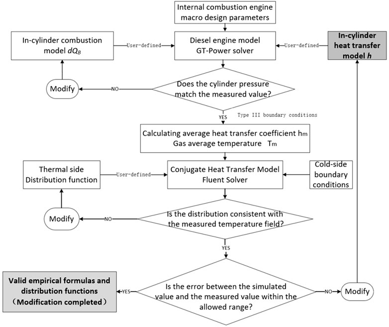
FIGURE 1. Block diagram of semi-empirical formula correction.
Experiments
Experimental Setup
In order to precisely modify the in-cylinder heat transfer model of diesel engines at various attitudes, the experiments on a single-cylinder diesel engine at different operation conditions were carried out. Proper sensors were utilized to measure the relevant parameters, such as pressure and temperature. The diesel engine specifications are shown in Table 1.
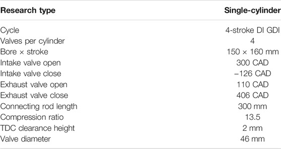
TABLE 1. Engine specifications.
This study used a four-stroke single-cylinder diesel engine. The engine speed was set to 1500 r/min (MBT), 1900 r/min, and 2200 r/min (rated condition). The different altitude (0, 1000, 2000, 3000, 3700, and 4500 m) environments were simulated by changing the intake pressure. All equipment and sensors have been calibrated precisely to ensure accuracy in the installation. The assembled test bench was equipped with a plateau simulation system that can change ambient pressures from 100 to 57.9 kPa. The ambient pressure at different operation conditions was precalculated in consideration of altitude and aspiration.
The NiCr–NiSi type thermocouples were arranged on the firing surface of the cylinder head in the test engine, and the specific locations of the measurement points are shown in Figure 2. A total of 10 measurement points were installed on the fire face located between the inlet and exhaust valves in the nose area and between the two exhaust valves. The sensor calibration revealed that the error is within ±0.1 °C, which can preciously capture the in-cylinder temperature. Moreover, the dynamic response time of this thermocouple is about 50 ∼ 100 ms, that meets the quick response requirement of the in-cylinder temperature measure.
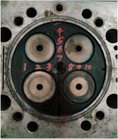
FIGURE 2. Physical diagram of thermocouples.
An NI data acquisition system that compiles NI-LabVIEW software with temperature measurement was used to collect data. As the sampling frequency of the temperature and strain data is 5 Hz and 100 kHz, respectively, a pair of independent hardware systems was utilized to ensure the system’s reliability and data accuracy.
Experimental Data
To describe the plateau simulation system, first, the pressure and temperature of the intake air were controlled; the parameters such as throttle opening and injection advance angle were adjusted. Once the single-cylinder engine has been stable, the experimental system would collect the temperature data and other engine parameters. The engine performance data, such as excess air coefficient and exhaust gas temperature at different altitudes, are shown in Figure 3.
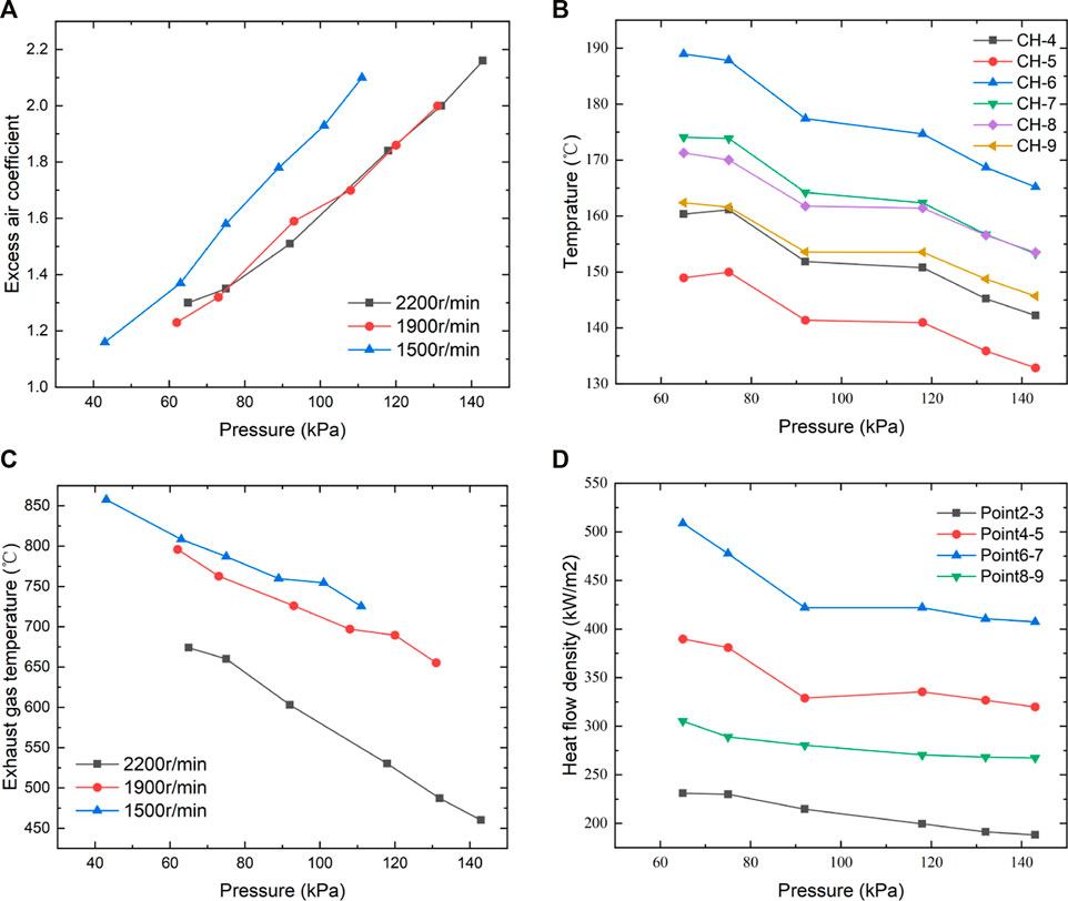
FIGURE 3. Excessive air coefficient (A), in-cylinder (B), exhaust gas (C) temperature, and heat flow density (D) with altitude.
It can be inferred from Figures 3A,B that with altitude rise, the exhaust air temperature rose while the excess air coefficient dropped, regardless of various engine speeds. As expected, the higher altitude corresponded to lower intake pressure and, therefore, less intake air, echoing the decreased excess air coefficient in Figure 3A. The probable reason for the trend of exhaust gas temperature was that the higher equivalence ratio indicated less in-cylinder mass but similar chemical heat released, contributing to exhaust gas temperature according to basic thermal rules. In addition, faster engine speed leads to decreased excess air coefficient and exhaust gas temperature, possibly because of the shortened duration of the air intake process. The deteriorated combustion at higher speed also contributed to lower exhaust gas temperature.
The data relating to the temperature field at the fire face were measured by the experiment. Figure 3C shows the temperature at the relevant measurement point on the cylinder head at 2,200 r/min. The heat flow density of the cylinder head, as shown in Figure 3D, was measured by the double-layer thermocouples arranged in advance.
Zero-Dimensional Combustion Model
To further investigate the heat transfer model by simulation, the zero-dimensional combustion model and in-cylinder heat transfer model, which are the main relevant submodels in GT-POWER, were used to calculate the boundary conditions, such as in-cylinder temperature and heat transfer coefficient, which can be the boundary conditions to a three-dimension numerical simulation model that calculates the temperature field.
A zero-dimensional in-cylinder combustion model (Sitkei and Ramanaiah, 1972) is used in this study; it can be described by the following equation:
where
Wiebe (Annand, 1963) proposed a semi-empirical formula for combustion rate based on the chemical reaction kinetics of a homogenous mixture:
where m is the combustion quality index, which determines the shape of the combustion heat release curve. The constant 6.908 was obtained if the period between the start of combustion and 99% of the fuel burned is assumed to be the end of combustion, according to the literature (Liu and Dumitrescu, 2019a) and (Wiebe, 1962). τ is dimensionless time, calculated with the following equation:
where φB is combustion initiation angle, φC is combustion termination angle, and ∆φ is combustion duration angle.
Thus, substituting Eq. 3 into Eqs1, 5 results in obtaining the calculation model of the combustion heat release rate:
In addition, the differential equation for the change of in-cylinder bulk temperature T can be obtained from the first law of thermodynamics (energy conservation equation) as follows:
where pdV is the mechanical work, which is the product of cylinder pressure and cylinder volume change rate; hjdmj is the energy, which is brought into the system by mass dmj; the combustion process can be calculated by Weibe exothermic law, intake and exhaust stroke process can be calculated by the intake and exhaust system energy equation; u is the specific internal energy; cv is constant volume specific heat; and dQi is the wall heat loss of the combustion chamber, which can be calculated by Newton’s cooling formula.
In-Cylinder Heat Transfer Model
Heat Transfer Model Without Consideration of Elevation
To establish an in-cylinder head conjugate heat transfer (CHT) model for diesel engines, the main control equations include the coolant turbulence model, solid thermal conductivity model, fluid–solid interface treatment, and in-cylinder transient heat transfer boundary conditions.
As mentioned in Experiments, the experiment can obtain the temperature, heat flow density, and other parameters. However, the heat transfer coefficient and gas temperature cannot be measured directly, which requires building a proper model. The main equations are briefly sorted out below.
The heat transfer of coolant flow in the cylinder head water chamber can be described by the standard k-ε turbulence model, whose main controlling equations are the turbulent pulsation energy equation and the turbulent dissipation rate equation, and the detailed information is shown in the study by Yu et al. (2014). Moreover, the thermal conductivity of the solid region of the cylinder head can be described by Eq. 7, namely:
where λ is the thermal conductivity, ρ is the density of the solid, cp is the specific heat capacity of the solid, Sv is the unit volume of heat generation power, and the non-linear effect with temperature is considered in material properties.
The heat flux and temperature at the fluid–solid interface of the cylinder head are equal and can be described by Eq. 8, namely:
where qw is the heat flow density at the interface, n is normal to the outside of the wall, h is the convective heat transfer coefficient, and Tw and T∞ are the temperatures of the fluid at the interface and the mainstream region, respectively.
The in-cylinder heat transfer coefficient h and gas temperature T are difficult to measure directly by experimental methods; T can be calculated by Eq. 6, and the instantaneous average heat transfer coefficient h is the in-cylinder heat transfer boundary model; its semi-empirical formula can be expressed in the following general form according to Liu et al. (2020).
where D is the cylinder bore; p is the instantaneous pressure in the cylinder; T is the instantaneous temperature in the cylinder; w is the function of the piston average speed, and Cm, n, c, and m are constants.
The instantaneous in-cylinder temperature and heat transfer coefficient are obtained from Eq. 6 and Eq. 9, which is based on Eq. 10 to obtain the corresponding average values.
where Tm is the integrated average gas temperature and hm is the cycle average heat transfer coefficient.
To describe the spatial distribution of the average heat transfer coefficient in the cylinder head fire surface, the variation of hm along the cylinder radial direction is written as a distribution function of the following equation.
where r is the distance from a point P on the fire surface to the cylinder center; r0 is the cylinder radius; hr is the heat transfer coefficient at point P; a0, a1, a2, and a3 are constant coefficients. The values are a0 = 0.5, a1 = 3, and a2 = -3 for the test model in this article.
Tm and hm is loaded to the cylinder head fire surface as the third type of boundary conditions, which can be used to solve the conjugate heat transfer model.
Heat Transfer Boundary Modification at Variable Altitudes
The semi-empirical equation shown in Eq. 9 is derived from the in-tube turbulence test correlation and experimental data. The f (p, T) is the part related to the in-cylinder mixture physical parameters. Moreover, mass density ρ, thermal conductivity λ, and viscosity η can be expressed as a function of temperature according to Woschni (1967) as shown in Eq. 12.
where the pressure index n = 0.8 and the temperature index m = a-(b+1)n.
The in-cylinder components differ with altitude changes due to degradation of combustion and reaction caused by lower intake pressure and, therefore, equivalence ratio. That is the main reason that the temperature index a, b changes and therefore the temperature index m in Eq. 13, as Liu and Dumitrescu (2019b supported.
Therefore, it is important to build a correlation formula about the temperature index m and altitude to simulate the heat transfer process at different altitudes.
The most commonly used semi-empirical model is the Woschni formula (Woschni, 1967), which has been modified by Hohenberg (1979), Huber et al. (1990). Comparing the characteristics and applicability of various in-cylinder heat transfer models, the Woschni formula (Woschni, 1967) was used as the basic model in this study, namely,
where h is the convective heat transfer coefficient, W/(m2·K); Cm is the average piston velocity, m/s; D is the cylinder diameter, m; p and T are the instantaneous pressure (Pa) and temperature (K) of the cylinder gas, respectively; p1, V1, and T1 are the pressure (Pa), volume (m3), and temperature (K) of the cylinder gas at the moment of IVC, respectively; Vs is the working volume of the cylinder, m3; p0 is the cylinder gas pressure(Pa) under the motored condition; c1 is the airflow velocity coefficient; c2 is the combustion chamber shape coefficient; m is the temperature index, and the initial value is -0.523.
The structural and operational parameters of the test model were input into the GT-Power model, and the user-defined heat transfer model code was compiled. The Woschni equation (Woschni, 1967) with customizable temperature index term m was loaded into the GT-Power software (Heywood, 2018). Moreover, the temperature index m was adjusted to calculate the average heat transfer coefficient hm and the average gas temperature Tm in the cylinder under different operating conditions.
In Fluent software, hm, Tm, and the wall distribution function (shown in Eq. 11) are loaded onto the cylinder head fire surface as the third type of boundary conditions by compiling the user-defined function (UDF) (Lefebvre, 2013); the cold side boundary, as well as other boundary conditions, is set up according to the test data. Finally, the conjugate heat transfer model is solved to obtain the cylinder head temperature field.
The measured and calculated results of the temperature field were compared to correct the heat transfer model. If the error between measured and calculated values is unacceptable, then the semi-empirical formula of the temperature index m would be adjusted to reduce the disparity until the model precision could meet the requirement.
All the correction results of the temperature index m at each altitude for engine speed of 1500 r/min, 1900 r/min, and 2200 r/min are summarized, as shown in Figure 4.
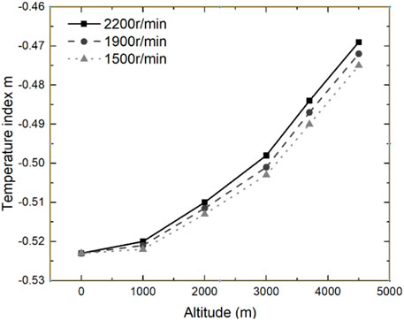
FIGURE 4. Results of temperature index m under various conditions.
The effect of altitude on the heat transfer model was carried out by mathematical statistics. The correspondence between temperature index m and intake pressure can be fitted by the least-squares method, and the fitting results are shown in Eq. 14.
where N is the engine speed (r/min), H is the altitude(m), b0 = 1.5, and b1 = 5.5 × 10⁻⁴.
Numerical Simulation Model
The numerical simulation of the diesel engine thermal state was calculated by the commercial software ANSYS Fluent in this study. The boundary conditions of the heating surface were obtained from the GT-Power model (Serrano et al., 2015), and the boundary conditions on the cooling surface were obtained from the measured data (He et al., 2013). The cylinder head could be divided into two parts: solid and liquid, where the liquid part is a double-layer cooling water jacket. The 3D model shown in Figure 5 was divided by tetrahedral meshing, and the minimum mesh size is 1∼2 mm. The total number of grids is controlled at 9.34 million after grid independence analysis.
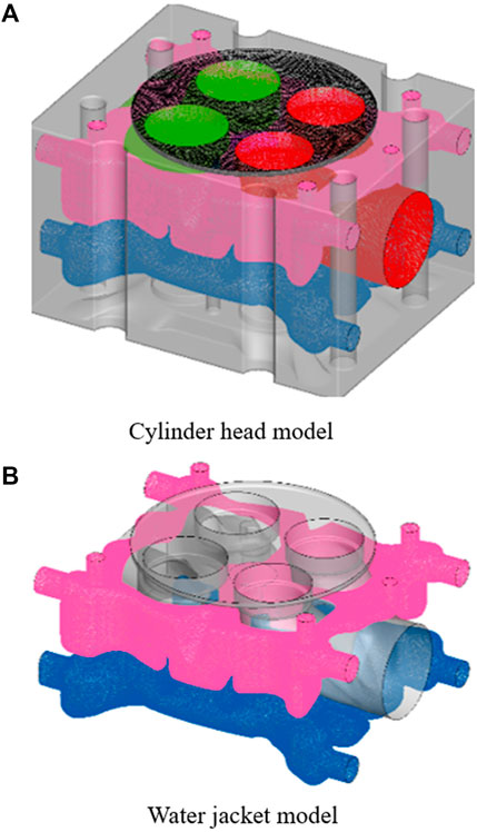
FIGURE 5. Geometry and mesh of the cylinder head (A) and water jacket (B).
The standard k-ε turbulence model (Kim et al., 2008; Liu and Dumitrescu, 2018) was used in this study to describe fluid flow, whose main controlling equations are the turbulent pulsation energy equation k and the turbulent dissipation ε rate equation (Yakhot and Orszag, 1986; Han and Reitz, 1995; Liu and Dumitrescu, 2019c; Liu and Dumitrescu, 2019d) as shown in the following equations:
where Gk is the turbulent energy caused by the mean velocity gradient, Gb is the turbulent energy due to buoyancy, YM represents the effect of fluctuating expansion incompressible turbulence on the total dissipation rate, C1ε, C2ε, and C3εare constants, σk, and σε are the turbulent Prandtl number of k and ε, respectively, and Sk and Sε are user-defined source terms.
The thermal conductivity controlling equation for the solid side and the heat transfer between the medium can be described by Eq. 7 and Eq. 8.
Results and Discussion
Numerical Simulation Validation
The result at the engine speed of 2200 r/min under the fixed altitude (4500 m) was chosen as a typical result to analyze. A zero-D calibrated diesel engine model was established that consisted of a combustion chamber module, a camshaft-piston module, a set of intake valves, and a set of exhaust valves. Moreover, the geometric design parameters of the single-cylinder engine as well as the test values of intake pressure, cyclic injection volume, and injection advance angle were input into the GT-Power model for calculation.
Meanwhile, the heat transfer model shown in Eq. 13 and Eq. 14 was written as a Fortran code, together with the GT model, to calculate the pressure, temperature, and convective heat transfer coefficient of the in-cylinder gas. The maximum burst pressure, torque, power, and exhaust gas temperature were compared with the measured values as shown in Table 2. The errors of each parameter were within 5%, indicating that the model successfully reflected engine performance.
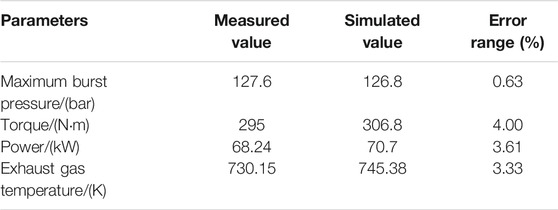
TABLE 2. Macro parameters of the diesel engine at plain.
The predicted and measured in-cylinder pressure, together with the heat transfer coefficient calculated by the original and modified model, are shown in Figure 6. The highly coincident pressure indicated a satisfied precision of the one-dimensional engine model. In addition, the heat transfer coefficient calculated by the modified model was apparently higher, corresponding to a 45.69% increment of the average value, which also proved the importance of heat transfer model correction.
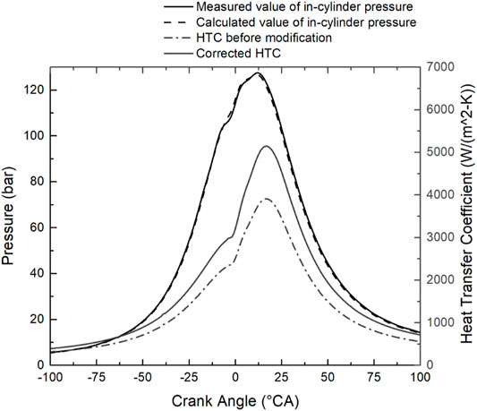
FIGURE 6. In-cylinder transient results at an altitude of 4500 m
The simulation results of the cylinder head temperature field are shown in Figure 6. To check the accuracy of the simulation results, the simulated and measured temperatures at the same position were compared, as Table 3 shows, implying that the errors are within 5%. Therefore, it was proven that the convective heat transfer model equation under this working condition is accurate enough.
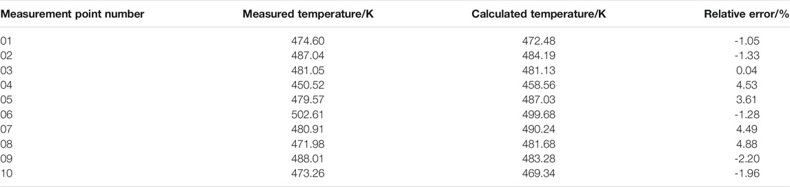
TABLE 3. Calculation solution and test data at an altitude of 4500 m
To further assess the precision of the modified heat transfer model, Figure 7 shows the simulated temperature distribution at X, Y direction (Figure 8) of the cylinder head and the measured data. It is of interest to figure out that the central depression of the temperature profile was probably caused by the central sunk surface, which reduced the local convection motion and, therefore, the heat transfer coefficient. In addition, the heat flow in the exhaust valve nose area was apparently higher, which was mainly due to the strong exhaust flow motion. The high coincidence of measured and calculated data suggested a satisfied accuracy of the corrected model.
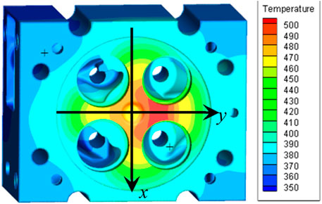
FIGURE 7. Numerical results of cylinder head temperature.
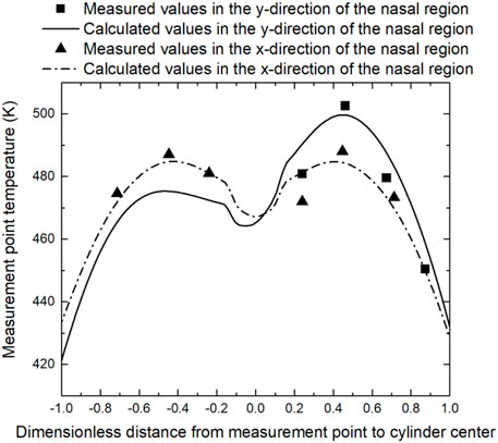
FIGURE 8. Cylinder head temperature distribution along the path in Figure 7.
Effect of Intake Air Pressure on Temperature Distribution
The distribution of the cylinder head temperature field for each altitude condition is shown in Figure 9. The peak temperature was located at the firing surface nose area on the exhaust port side. With the altitude rise, the maximum temperature increased, indicating that the deterioration of combustion also contributed to more severe post-combustion, resulting in a higher heat transfer coefficient. That is the probable reason for the increased peak temperature at the cylinder head.
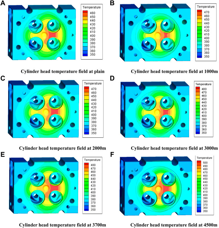
FIGURE 9. Simulation of the cylinder head temperature field at various altitude from 0 to 4,500 m (A–F) at 2,200 r/min.
Effect of Intake Air Pressure on Power Performance
The test data for the 2200 r/min operating condition at the maximum power point are shown in Figures 10, 11. As can be seen from Figure 10, torque and power decreased with altitude rise, probably due to reduced air pressure. The torque dropped from 290 N·m to 265 N·m, and power dropped from 66.81 to 61.05 kW.
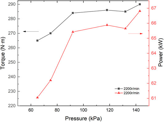
FIGURE 10. Torque and power with altitude at 2200 r/min.
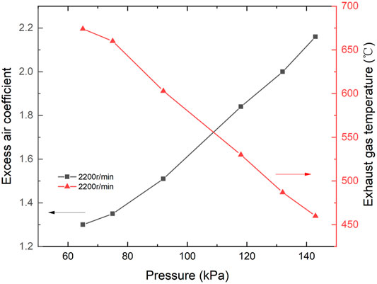
FIGURE 11. Excess air coefficient and exhaust gas temperature with altitude at 2200 r/min.
Figure 11 shows the excess air coefficient and exhaust gas temperature at each altitude. With the altitude rise, the exhaust gas temperature was gradually rising as analyzed above. In addition, the intake pressure being too low at the last two altitudes, the exhaust temperature exceeded the test safety limits, and the oil supply parameters were adjusted to reduce the torque.
It was also important to point out that there was a sudden change in the exhaust temperature and excess air coefficient as the altitude increased from 2000 to 3000 m because these altitudes corresponded to a sudden drop in intake pressure.
Therefore, it can be concluded that under calibration conditions, as the altitude rises, the temperature field of the cylinder head fire surface, exhaust temperature, excess air coefficient, and other parameters increase, indicating that the engine’s combustion deteriorates due to reduced intake volume and decreased excess air coefficient. Therefore, the concentration of soot in the exhaust gas increases, and then the exhaust temperature increases. However, the thermal state of the engine changed abruptly when the altitude rose to 3000 m. When the altitude rose from 0 to 4500 m, the exhaust gas temperature increased by 46.52%, and the excess air coefficient decreased by 39.81%.
Summary and Conclusion
In this study, the in-cylinder heat transfer model has been modified based on simulation analysis and experimental verification. The results indicated that the modified heat transfer model can be used in variable altitude operating conditions, and the main conclusions are as follows.
(1) By comparing different heat transfer correlations, the Woschni formula is selected as the basic model. The temperature index m in the formula is determined as the key correction variable by analyzing the effect of altitude on the model parameters.
(2) A conjugate heat transfer model has been established, and the in-cylinder working process and cylinder head temperature field distribution have been calculated. To obtain the in-cylinder heat transfer model applicable to variable altitudes, the relationship between temperature index m, altitude H, and engine speed N was fitted by the least-squares method. The results indicated that the average heat transfer coefficient hm increased by 45.69% after correction, which also suggests that the traditional model could no longer adapt to the requirements of variable altitudes.
(3) The new modified model is used to calculate the results under different engine speeds at variable altitudes. By comparing the calculation results with the test results, it is found that the errors of the model are less than 5%. Therefore, the new model has good adaptability and precision under various altitudes of operating conditions.
Data Availability Statement
The raw data supporting the conclusion of this article will be made available by the authors, without undue reservation.
Author Contributions
YZ: conceptualization, methodology, simulation, and writing‐draft preparation; YY: simulation, writing-draft preparation; RY: validation and writing-draft preparation; QW: simulation and writing-draftpreparation; BZ: analysis; QG: analysis; ZL: analysis and supervision; JF: methodology and validation.
Funding
The study was jointly funded by the Natural Science Foundation of Zhejiang Province (LQ20E060003), the Project Teacher Research Fund Project (J-202116), and the Projects of Hangzhou Agricultural and Social Development Research Program (20201203B128 and 20212013B04).
Conflict of Interest
The authors declare that the research was conducted in the absence of any commercial or financial relationships that could be construed as a potential conflict of interest.
Publisher’s Note
All claims expressed in this article are solely those of the authors and do not necessarily represent those of their affiliated organizations, or those of the publisher, the editors, and the reviewers. Any product that may be evaluated in this article, or claim that may be made by its manufacturer, is not guaranteed or endorsed by the publisher.
References
Ambrogi, L., Liu, J., Battistoni, M., Dumitrescu, C. E., and Gasbarro, L. (2019). CFD Investigation of the Effects of Gas’ Methane Number on the Performance of a Heavy-Duty Natural-Gas Spark-Ignition Engine. SAE Tech. Paper 1, 1. doi:10.4271/2019-24-0008
Annand, W. J. (1963). Heat Transfer in the Cylinders of Reciprocating Internal Combustion Engines. Proc. Inst. Mech. Eng. 177 (1), 973–996.
Borman, G., and Nishiwaki, K. (1987). Internal-combustion Engine Heat Transfer. Prog. Energ. Combustion Sci. 13 (1), 1–46. doi:10.1016/0360-1285(87)90005-0
Broekaert, S., Demuynck, J., De Cuyper, T., De Paepe, M., and Verhelst, S. (2016). Heat Transfer in Premixed Spark Ignition Engines Part I: Identification of the Factors Influencing Heat Transfer. Energy 116, 380–391. doi:10.1016/j.energy.2016.08.065
Chen, X., Yu, X., Lu, Y., Huang, R., Liu, Z., Huang, Y., et al. (2017). Study of Different Cooling Structures on the thermal Status of an Internal Combustion Engine. Appl. Therm. Eng. 116, 419–432. doi:10.1016/j.applthermaleng.2017.01.037
De Cuyper, T., Demuynck, J., Broekaert, S., De Paepe, M., and Verhelst, S. (2016). Heat Transfer in Premixed Spark Ignition Engines Part II: Systematic Analysis of the Heat Transfer Phenomena. Energy 116, 851–860. doi:10.1016/j.energy.2016.10.032
Fagundez, J. L. S., Sari, R. L., Martins, M. E. S., and Salau, N. P. G. (2017). Comparative Analysis of Different Heat Transfer Correlations in a Two-Zone Combustion Model Applied on a SI Engine Fueled with Wet Ethanol. Appl. Therm. Eng. 115, 22–32. doi:10.1016/j.applthermaleng.2016.12.121
Gholinia, M., Pourfallah, M., and Chamani, H. R. (2018). Numerical Investigation of Heat Transfers in the Water Jacket of Heavy Duty Diesel Engine by Considering Boiling Phenomenon. Case Stud. Therm. Eng. 12, 497–509. doi:10.1016/j.csite.2018.07.003
Han, Z., and Reitz, R. D. (1995). Turbulence Modeling of Internal Combustion Engines Using RNG κ-ε Models. Combustion Sci. Technology 106 (4-6), 267–295. doi:10.1080/00102209508907782
Han, Z., and Reitz, R. D. (1997). A Temperature wall Function Formulation for Variable-Density Turbulent Flows with Application to Engine Convective Heat Transfer Modeling. Int. J. Heat Mass Transfer 40 (3), 613–625. doi:10.1016/0017-9310(96)00117-2
He, W. F., Dai, Y. P., Wang, J. F., Li, M. Q., and Ma, Q. Z. (2013). Performance Prediction of an Air-Cooled Steam Condenser Using UDF Method. Appl. Therm. Eng. 50 (1), 1339–1350. doi:10.1016/j.applthermaleng.2012.06.020
Hohenberg, G. F. (1979). Advanced Approaches for Heat Transfer Calculations. SAE Tech. Paper 1, 790825. doi:10.4271/790825
Huber, K., Woschni, G., and Zeilinger, K. (1990). Investigations on Heat Transfer in Internal Combustion Engines under Low Load and Motoring Conditions. SAE Tech. Paper 1, 905018.
Kim, H.-M., Park, S.-K., Choi, K.-S., Wang, H.-M., Lee, D.-H., Lee, D.-K., et al. (2008). Investigation on the Flow and Heat Transfer Characteristics of Diesel Engine EGR Coolers. Int.J Automot. Technol. 9 (2), 149–153. doi:10.1007/s12239-008-0019-4
Launder, B. E., and Spalding, D. B. (1974). The Numerical Computation of Turbulent Flows. Computer Methods Appl. Mech. Eng. 3 (2), 269–289. doi:10.1016/0045-7825(74)90029-2
Lefebvre, A. H. (2013). Ignition Theory and its Application to the Altitude Relighting Performance of Gas Turbine Combustors. Combustion Heat Transfer Gas Turbine Systems: Proc. Int. Propulsion Symp. 11, 105.
Liu, J., Dumitrescu, C. E., and Bommisetty, H. (2019). An Experimental Study of the Combustion Process in a Natural-Gas Spark-Ignition Engine. American Society of Mechanical Engineers 2019. Int. Mech. Eng. Congress Exposition 1, IMECE2019–11637. doi:10.1115/imece2019-11637
Liu, J., and Dumitrescu, C. E. (2019). Lean-burn Characteristics of a Heavy-Duty Diesel Engine Retrofitted to Natural-Gas Spark Ignition. J. Eng. Gas Turbines Power 141 (7), 071013. doi:10.1115/1.4042501
Liu, J., Huang, Q., Ulishney, C., and Dumitrescu, C. E. (2022). Comparison of Random forest and Neural Network in Modelling the Performance and Emissions of a Natural Gas Spark Ignition Engine. J. Energ. Resour. Technology 144 (3), 032310. doi:10.1115/1.4053301
Liu, J., Ulishney, C., and Dumitrescu, C. E. (2020). Characterizing Two-Stage Combustion Process in a Natural Gas Spark Ignition Engine Based on Multi-Wiebe Function Model. J. Energ. Resour. Technology 142 (10), 102302. doi:10.1115/1.4046793
Liu, J., and Dumitrescu, C. E. (2018). 3D CFD Simulation of a CI Engine Converted to SI Natural Gas Operation Using the G-Equation. Fuel 232, 833–844. doi:10.1016/j.fuel.2018.05.159
Liu, J., and Dumitrescu, C. E. (2019). Analysis of Two-Stage Natural-Gas Lean Combustion inside a Diesel Geometry. Appl. Therm. Eng. 160, 114116. doi:10.1016/j.applthermaleng.2019.114116
Liu, J., and Dumitrescu, C. E. (2019). Numerical Investigation of Methane Number and Wobbe index Effects in Lean-Burn Natural Gas Spark-Ignition Combustion. Energy Fuels 33 (5), 4564–4574. doi:10.1021/acs.energyfuels.8b04463
Liu, J., and Dumitrescu, C. E. (2019). Single and Double Wiebe Function Combustion Model for a Heavy-Duty Diesel Engine Retrofitted to Natural-Gas Spark-Ignition. Appl. Energ. 248, 95–103. doi:10.1016/j.apenergy.2019.04.098
Liu, J., and Wang, H. (2022). Machine Learning Assisted Modeling of Mixing Timescale for LES/PDF of High-Karlovitz Turbulent Premixed Combustion. Combustion and Flame 238, 111895. doi:10.1016/j.combustflame.2021.111895
Liu, Z., and Liu, J. (2021). Effect of Altitude on in-cylinder Heat Transfer of a Heavy Duty Diesel Engine. American Society of Mechanical Engineers 2021. Heat Transfer Summer Conf. 1, HT2021–62351. doi:10.1115/ht2021-62351
Liu, Z., and Liu, J. (2021). “Effects of Increased Altitude on the Diesel Engine Performance,” in The 2nd World Congress on Internal Combustion Engines, P0387.
Liu, Z., and Liu, J. (2021). Experimental Investigation of Combustion Characteristics of a Single cylinder Diesel Engine at Altitude. J. Energ. Resour. Technology 143 (10), 102306. doi:10.1115/1.4050575
Liu, Z., Zhang, Y., Fu, J., and Liu, J. (2021). Three-dimensional Fluid Dynamics Modeling of a 6V150 Diesel Engine. American Society of Mechanical Engineers 2011. International Mechanical Engineering Congress and Exposition, IMECE2021–67711.
Liu, Z., and Liu, J. (2022). Effect of Altitude Conditions on Combustion and Performance of a Turbocharged Direct-Injection Diesel Engine. Proc. Inst. Mech. Eng. D: J. Automobile Eng. 236 (4), 582–593. doi:10.1177/09544070211026204
Lu, X., Li, Q., Zhang, W., Guo, Y., He, T., and Zou, D. (2013). Thermal Analysis on Piston of marine Diesel Engine. Appl. Therm. Eng. 50 (1), 168–176. doi:10.1016/j.applthermaleng.2012.06.021
Lu, Y., Zhang, X., Xiang, P., and Dong, D. (2017). Analysis of thermal Temperature fields and thermal Stress under Steady Temperature Field of Diesel Engine Piston. Appl. Therm. Eng. 113, 796–812. doi:10.1016/j.applthermaleng.2016.11.070
Michl, J., Neumann, J., Rottengruber, H., and Wensing, M. (2016). Derivation and Validation of a Heat Transfer Model in a Hydrogen Combustion Engine. Appl. Therm. Eng. 98, 502–512. doi:10.1016/j.applthermaleng.2015.12.062
Perez, P. L., and Boehman, A. L. (2010). Performance of a Single-cylinder Diesel Engine Using Oxygen-Enriched Intake Air at Simulated High-Altitude Conditions. Aerospace Sci. Technology 14 (2), 83–94. doi:10.1016/j.ast.2009.08.001
Serrano, J., Olmeda, P., Arnau, F., and Dombrovsky, A. (2015). General Procedure for the Determination of Heat Transfer Properties in Small Automotive Turbochargers. SAE Int. J. Engines 8 (1), 30–41. doi:10.4271/2014-01-2857
Shannak, B. A., and Alhasan, M. (2002). Effect of Atmospheric Altitude on Engine Performance. Forschung Im Ingenieurwesen 67 (4), 157–160. doi:10.1007/s10010-002-0087-y
Shen, L., Shen, Y., Yan, W., and Xu, J. (1995). Combustion Process of Diesel Engines at Regions with Different Altitude. SAE Tech. Paper 1, 950857. doi:10.4271/950857
Sideri, M., Berton, A., and D’Orrico, F. (2017). Assessment of the wall Heat Transfer in 3D-CFD in-cylinder Simulations of High Performance Diesel Engines. Energ. Proced. 126, 963–970. doi:10.1016/j.egypro.2017.08.187
Sitkei, G., and Ramanaiah, G. V. (1972). A Rational Approach for Calculation of Heat Transfer in Diesel Engines. SAE Tech. Paper 1, 720027. doi:10.4271/720027
Sroka, Z. J. (2012). Some Aspects of thermal Load and Operating Indexes after Downsizing for Internal Combustion Engine. J. Therm. Anal. Calorim. 110 (1), 51–58. doi:10.1007/s10973-011-2064-x
Stocchi, I., Liu, J., Dumitrescu, C. E., Battistoni, M., and Grimaldi, C. N. (2019). Effect of Piston Crevices on the Numerical Simulation of a Heavy-Duty Diesel Engine Retrofitted to Natural-Gas Spark-Ignition Operation. J. Energ. Resour. Technology 141 (11), 112204. doi:10.1115/1.4043709
Wang, X., Ge, Y., Yu, L., and Feng, X. (2013). Effects of Altitude on the thermal Efficiency of a Heavy-Duty Diesel Engine. Energy 59, 543–548. doi:10.1016/j.energy.2013.06.050
Wiebe, I. (1962). Progress in Engine Cycle Analysis: Combustion Rate and Cycle Processes. Ural-Siberia Branch: Mashgiz, 271.
Woschni, G. (1967). A Universally Applicable Equation for the Instantaneous Heat Transfer Coefficient in the Internal Combustion Engine. SAE Tech. Paper 1, 670931. doi:10.4271/670931
Yakhot, V., and Orszag, S. A. (1986). Renormalization Group Analysis of Turbulence. I. Basic Theory. J. Sci. Comput. 1 (1), 3–51. doi:10.1007/bf01061452
Yang, M., Gu, Y., Deng, K., Yang, Z., and Zhang, Y. (2018). Analysis on Altitude Adaptability of Turbocharging Systems for a Heavy-Duty Diesel Engine. Appl. Therm. Eng. 128, 1196–1207. doi:10.1016/j.applthermaleng.2017.09.065
Yu, L., Ge, Y., Tan, J., He, C., Wang, X., Liu, H., et al. (2014). Experimental Investigation of the Impact of Biodiesel on the Combustion and Emission Characteristics of a Heavy Duty Diesel Engine at Various Altitudes. Fuel 115, 220–226. doi:10.1016/j.fuel.2013.06.056
Zhang, B., Liu, Z., Zhang, Y., Chen, S., and Yu, X. (2016). Changing Regularity of Diesel cylinder Head's thermal State under Variable Altitude Condition. J. Mech. Electr. Eng. 33 (10), 1203–1207.
Keywords: variable altitude, diesel engine, conjugate heat transfer, in-cylinder heat transfer model, CFD
Citation: Zhang Y, Yan Y, Yang R, Wang Q, Zhang B, Gan Q, Liu Z and Fu J (2022) Study of In-Cylinder Heat Transfer Boundary Conditions for Diesel Engines Under Variable Altitudes Based on the CHT Model. Front. Energy Res. 10:828215. doi: 10.3389/fenrg.2022.828215
Received: 03 December 2021; Accepted: 13 January 2022;
Published: 23 February 2022.
Edited by:
Jun Li, Guangzhou Institute of Energy Conversion (CAS), ChinaReviewed by:
Long Wu, Tianjin University of Science and Technology, ChinaYaojie Tu, Huazhong University of Science and Technology, China
Copyright © 2022 Zhang, Yan, Yang, Wang, Zhang, Gan, Liu and Fu. This is an open-access article distributed under the terms of the Creative Commons Attribution License (CC BY). The use, distribution or reproduction in other forums is permitted, provided the original author(s) and the copyright owner(s) are credited and that the original publication in this journal is cited, in accordance with accepted academic practice. No use, distribution or reproduction is permitted which does not comply with these terms.
*Correspondence: Jiahong Fu, ZnVqaEB6dWNjLmVkdS5jbg==