- 1School of Electrical and Information Engineering, Changsha University of Science and Technology, Changsha, China
- 2College of Electrical and Information Engineering, Hunan University of Technology, Zhuzhou, China
Precise estimation of position is essential in the control of switched reluctance motors (SRMs). Traditionally, the intersection of the adjacent inductance can be utilized to estimate the rotor position, however, magnetic saturation brings about variations in the intersection position when the motor is operated at heavy load. To solve this problem, this paper develops a sensorless position estimation strategy considering magnetic saturation and the embrace design. Sensorless control approaches can be chosen interchangeably according to the characteristics of the intersection. Rotor position estimation is achieved by employing six typical inductance positions. No additional position sensor and other detection devices are required. Through simulation and experiment, the feasibility and validity of the proposed position estimation method are verified. The proposed sensorless method is verified for acceleration, constant operated state, and load mutation.
1 Introduction
With the development of new energy technology Huang et al. (2021); Zhang et al. (2021), switched reluctance motors (SRMs) have been widely used in manufacturing due to their simplicity, fault tolerance, and low cost, which make them very competitive in the market Hu et al. (2015); Elmas et al. (1996); Sato et al. (2016).
The stable operation of switched reluctance motors relies on accurate rotor position information in which the commutation should be made at a proper position to operate the motor efficiently Bateman et al. (2010); Wang and Fahimi (2014); Afjei and Nezamabadi (2016). Traditionally, position sensors such as hall-effect, resolvers, and other mechanical sensors are required, and additional circuitry is also applied to commutate which endows the motor with a fast dynamic response Ma et al. (1998); Chang et al. (2015). However, traditional position sensors are susceptible to harsh environments. Meanwhile, installation accuracy is also an important factor which should be taken into consideration. These unreliable complications possibly reduce the competitiveness of the motor Mese and Torrey (2002); Xu and Wang (2002); Krishnamurthy et al. (2006). Therefore, the development of reliable sensorless position technology is of great significance to the application of switched reluctance motors Torkaman and Afjei (2013); Khalil et al. (2005).
Recently, domestic and foreign scholars have conducted extensive research on sensorless position technology. A few instances of sensorless schemes such as high-frequency injectionYu and Chen (2006) and intelligence techniques such as ANN, MARS observers, and fuzzy logics have beenreported in the literature Cheok and Ertugrul (2000); De et al. (2011); Hudson et al. (2008).
Accurately estimated position is obtained and low-speed performance is improved when using the fuzzy logic-based scheme described in Cheok and Ertugrul (2000); De et al. (2011). With neuro fuzzy learning by training the phase voltage and current signal using a backpropagation algorithm, the rotor position is estimated successfully under high noise conditions. However, the application of intelligent techniques studied by many researchers is only suitable for low-speed operation in SRM drives.
Based on the injection method, one prime idea behind these approaches comes from the fact that the inherent characteristics of SRM, such as back-EMF, phase inductance, flux linkage, etc., are a function of rotor position Cai and Deng (2015); Gao et al. (2004). By measuring the phase current and voltage of the terminal, the electromagnetic characteristics are obtained, thus, rotor position information is able to be extracted.
High-frequency signals are injected in the non-energized phase during the interval, and by extracting the information of the rate of change of the current with the slope difference strategy, full-cycle phase inductance corresponding to the position is identified Cai and Deng (2013). High-frequency voltage pulses are injected, vectors are defined, and the composed vector is combined by the decomposition method, therefore the position is estimated Cai and Deng (2012). Only one current sensor is applied to detect the position online Cao et al. (2016), the excitation current is separated from the bus current, and the rotor information is extracted by current-rise-time at low speed and the current-gradient method at the high-speed condition. High-frequency pulses are hard to inject when the motor is operated at the high-speed condition, a single pulse is injected to determine the position for the high-speed condition in Ofori et al. (2015), and the injection method is extended to the high-speed condition.
With the previous injection method, an inductance calculation or current threshold is required, the inductance is able to be obtained by using look-up tables or employing analytical methods taking up the space of DSP.
Recently, some intelligent algorithms have been applied to the sensorless position control strategy. The idea of adopting an ANN algorithm as a position estimation method was suitable for low-speed conditions in Barnard et al. (2014); Jakobsen et al. (2015); Kuai et al. (2017).
This paper proposes a new sensorless position control strategy for SRM drives, based on magnetic saturation and the embrace design. The relationship between the embrace value and the intersection position is fully investigated, it is found that in the low inductance region, the intersection position is not sensitive to the saturation current when the embrace is small. Thus, the typical specific position can be used as an update point for position estimation. Obviously, the intersection position is influenced to a great extent when the embrace is larger; the relationship between the saturation current and the intersection position needs to be explored. In the high inductance region, the intersection position is a function of the saturation current. Firstly, an identification of full-cycle phase inductance of the SRM based on the current slope difference method is performed. Secondly, the relationship between the embrace value and the intersection position is fully investigated. The result shows that the intersection position in the low inductance region is not sensitive to the saturation current when the embrace is set to a small region, thus, the typical specific position can be used as an update point for position estimation. Apparently, the intersection position is greatly influenced when the embrace is marginally larger, the intersection position must be compensated, thus the relationship between the saturation current and the intersection position must be explored, and the function of the saturation current and intersection position is obtained. Consequently, these sensorless control approaches can be chosen interchangeably according to the characteristics of the intersection defined by the embrace.
Compared with the inductance-based method mentioned above, the proposed scheme possesses the following main contributions:
(1) The rotor estimation is achieved by employing typical intersections without a requirement of an additional position sensor and other detection devices, meanwhile the relationship between the inductance and position is unnecessary, which releases the DSP memory. Furthermore, a priori magnetic characteristic knowledge of SRM is not required and the computation process is simple.
(2) The special intersections adopted for the sensorless scheme can be chosen according to the embrace, when the embrace is small, the intersections at the low inductance region are insensitive to the saturation effect, and by utilizing these intersections, the estimation performance is not affected by saturation. When the embrace is marginally larger, six compensated intersections are implemented. The estimated accuracy is also guaranteed even if the motor is operated at a saturation condition.
(3) The estimation of speed and position can be updated six times per 360 °electrical angle, there is no accumulated error, and the accuracy of speed and position estimation can be guaranteed whenever the motor is operated in the acceleration state, at high speed and heavy load. The organization of this paper is as follows.
Section 2 shows the mathematic analysis of acquiring the phase inductance in real time, and the relationship between the embrace and the intersections are analyzed. Issues related to phase intersections based on the embrace of the SRM are demonstrated in Section 3. The evaluation of the proposed estimation approach for a 5.5 kW SRM is presented in Section 4. And a comparative analysis between the proposed and inductance-based position estimations is given in Section 5.
2 Acquisition of Incremental Inductance
2.1 Nonlinear Characteristics of the SRM
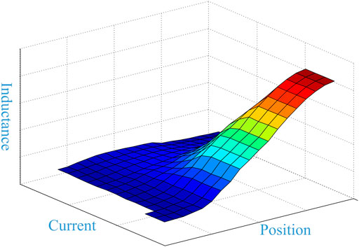
For the 12 stators/6 rotor poles in the SRM, the relationship between the phase inductance and the current rotor position is shown in Figure 1. Traditionally, the motor is operated at the saturated magnetic condition to obtain a large torque, thus the highly saturated magnetic circuit of the motor needs to be designed. As a result, the interdependence between inductance with position and current is highly nonlinear.
2.2 Acquirement of Inductance Profile
The SRM phase voltage equation is as follows:
The partial derivative is rewritten as:
Considering the mutual inductance, the flux linkage is deduced by the expression:
Where Lk,k is the k-phase self-inductance and Mk,k−1 is the mutual inductance between the k-phase and k-1 phase, and the k-phase voltage equation is shown as:
The k-1 phase flux linkage is expressed as:
Then the k-1 phase voltage equation can be presented as:
Where the k-phase incremental inductance can be obtained by formula (7), and the k-phase incremental mutual inductance can be obtained by formula (8).
The k phase and k-1 phase voltage expressions are derived as:
Where the k-1 phase incremental inductance Linck−1 can be obtained by formula (11), and the k-1 phase incremental mutual inductance can be obtained by formula (12):
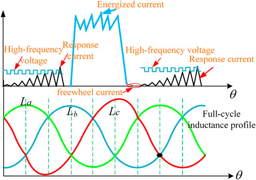
As shown in Figure 2, phase A, phase B, and phase C inductance profiles are consistent. The difference is a determined angle between the inductance profiles, which is related to the number of stator and rotor poles. For ideal SR motor model, inductance La, Lb, and Lc should be a perfectly symmetrical waveform. Actually, in the manufacturing process, process deviation, material deviation, or air gap inequality will cause inductance deviation. Lc is just an example of asymmetry, which is illustrated and added in the paper in Figure 2 When the motor is operated at an unsaturated state, the junction position of the inductance is not related to the current. When the motor is operated at a saturated state, the inductance junction is related to the magnitude of the current. Generally, a high-frequency injection is injected at the unsaturated operating state with the same amplitude and equal frequency. In the unsaturated operating region, the current response is notable and the features are able to obtain the inductance profile. In the high-frequency voltage injection method, the fixed and equal amplitude frequency voltage pulses are excited on the phase, and the current response is varied with the inductance, which is shown in Figure 3.
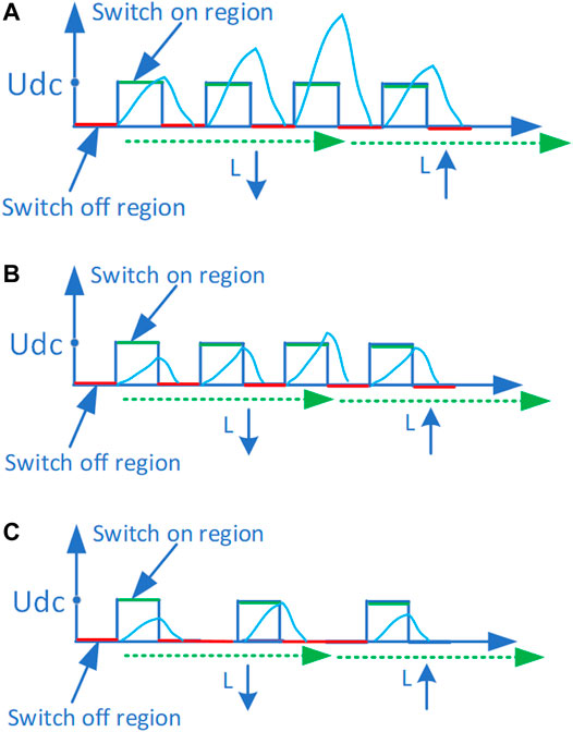
FIGURE 3. (A) High-frequency voltage injection method in unsaturated region (B) high-frequency voltage injection method in saturated region, and (C) high-frequency voltage injection method in high-speed region.
For Figures 2, 3 it is relevant to include some discussion about the impact of the SRM load (due to saturation) and speed (due to back-EMF) in the effectiveness of the injected voltage pulse method.
1) Running in the unsaturated region.
When the motor is operated in the unsaturated region, the distinction of the current response is significant in the injected voltage pulse method.
2) Running in the saturated region.
When the motor is operated in the saturated region, the distinction of the current response is small in the injected voltage pulse method.
3) Running in the high-speed region.
When the motor is operated in the high-speed region, the distinction of the current response is small due to back-EMF, and fewer pulses are able to be injected due to the short interval. So the injected voltage pulse method is not applicable.
The inductances of the ideal phase and the energized phase should be calculated in real time by using the excited current and injection response current. The equations of energized mode, freewheel mode, and demagnetization are shown in (13-15), respectively.
Formula (16) can be obtained after two formula (13), formula 15 are subtracted Cai and Deng (2015):
Mutual inductance is a prominent factor to the precision of the proposed sensorless control approach, but is not present concretely in this paper. Mutual inductance will be taken into consideration in the following research. In this paper, mutual inductances are neglected, as shown in (16) and 17.
According to the expression (7), the inductance can be further expressed as:
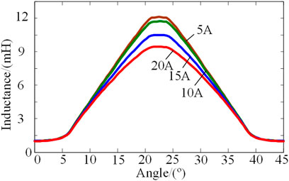
Assuming that the bus voltage is constant, the inductance curve with different currents is shown in Figure 4:
3 Principle of Proposed Estimation Position Method
3.1 Analysis of the Relationship Between the Embrace and Inductance Intersections
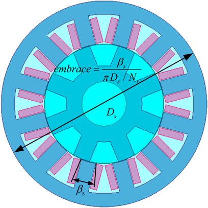
The characteristics of the intersection will be significantly distinctive when choosing different embrace designs. The embrace is defined as the ratio of the polar arc width to the polar distance. The polar arc width refers to the arc length, the polar distance refers to the arc length, and the ratio of the arc length on two identical circles is also the ratio of their angles, as shown in Figure 5. At the same time, the embrace also reflects the distribution of the air gap magnetic density. Assuming the embrace is small, it is found that the intersection position in the low inductance region is almost coincidental and insensitive to the magnetic saturation. On the contrary, these intersection positions are greatly different when the embrace is marginally larger.
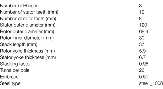
The Ansoft modes of the 12/8-pole SRM with different embrace designs are demonstrated in Figure 6, and the specific structure parameters of the 12/8 motor is listed in Table 1. Obviously, when the embrace design is set to 0.4, the intersection between inductance A and inductance C profiles is approximately 7.5°, which is insensitive to the saturation current. And the disparity is too large for the intersections in the high inductance region.
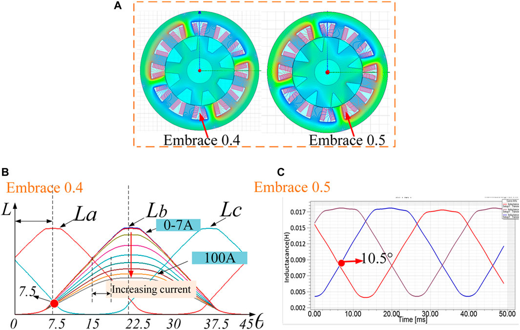
FIGURE 6. (A) A variety of SRM designs with 12/8 (B) the intersection position is located in the low inductance region in 12/8 (C) the intersection position is located in the high inductance region in 12/8.
However, the position of the inductance profile intersection reaches 10.5°when the embrace is set to 0.5, about a 2°mechanical angle transformation compared with that using the small embrace parameter. The feature of inductance profile is able to contribute to the development of the sensorless strategy as well as form good guidance for motor design.
This typical position is applied in the position estimation.
The unsaturation inductance profiles are represented in Figure 7. It is notable that the six intersection positions are specific and almost no variation is achieved, these intersections ought to be in the ideal position for the sensorless scheme. Nevertheless, the motor is almost operated at the saturation state and these typical intersections are not suitable anymore. Another investigation is made to test the saturation accommodation method.
Compared with the simulation results exhibited in Figure 8, the following indications are achieved. It can be seen that the feature of the intersection in the low inductance region is quite different to that in the high inductance region. The position of the intersection between inductance profiles Lb and La is insignificantly different to the C of the saturation current. By employing the determined angle of the intersections, which are 11.6°and 14.8°, respectively, the corresponding unsaturation current is 5A and the saturation current is 20A. The maximum difference is about 2.8°(mechanical angle), and the case will be deteriorated as the saturation current increases. Based on the above analysis, the possibility of employing the intersection of the low inductance region in sensorless control will be investigated in this paper.
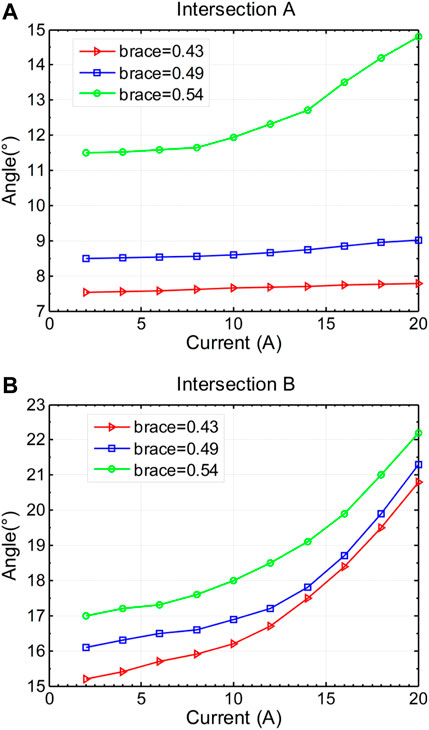
FIGURE 8. (A) The angle of the intersection between inductance profile B and inductance profile C with difference embrace designs (B) The angle of the intersection between inductance profile A and inductance profile B with difference embrace designs.
Sensorless control schemes are chosen with the embrace parameter; a detailed description will be introduced in the following section.
3.2 Sensorless Control Scheme Considering Saturation When the Embrace Is Set Below the Design Threshold
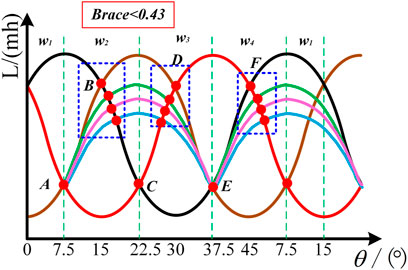
For embrace designs under 0.43, the intersections of the inductance profiles in the low inductance region are demonstrated in the diagram in Figure 9. Point A, point C, and point E corresponding to 7.5°, 22.5°, and 37.5°are utilized to estimate the speed in the proposed sensorless scheme.
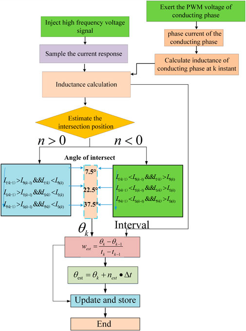
The flow chart of the sensorless method using the three typical intersections is shown in Figure 10. When the motor is operated inthe forward direction, the intersections can be identified by judging the relationship of the adjacent inductance profile. Taking intersection A for example, at k instant, the inductance La is judged to be larger than Lb, meanwhile, the inductance Lc is larger than Lb at the following sampling instant, and the unique identification for the position of intersection A is, once the instant of intersection A and intersection B is confirmed, the average speed between the intersections is able to be calculated by using the counter of DSP.
The motor rotor position estimation at any instant is then rewritten as follows:
where θk stands for the rotor update position point, △θ represents the partial angle spacing between adjacent typical intersection points, which is considered a constant value of 15°, △tk is the rotor rotation time from one typical position to the other, tk is the kth moment of the updated point, and t1 represents any moment when the rotor rotates between two typical points, the related formulas are revealed in Table 2.
3.3 Sensorless Scheme When the Embrace Is Above the Threshold
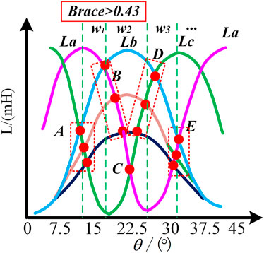
Another condition is necessary to be studied in the proposed sensorless approach. The characteristic of intersections at low inductance is homologous to that of high inductance when the embrace is set over 0.43, which is highly different to that when the embrace is set to less than 0.43. Thus the sensorless strategy should be reconsidered with the aforementioned difference. The relationship between the position of the intersection and the saturation current is revealed in Figure 11.
Obviously, it can be concluded that the position of the intersection is greatly sensitive to the saturation effect whenever theintersections are in the low or high inductance regions. It is necessary to study the relationship between the position of intersections and the saturation current.
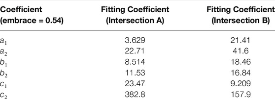
The Gaussian fitting mathematical expression is established to describe the relationship between the saturation current and the intersection position. The discrete data containing the information of the saturation current and intersection position are obtained by experiment. Obviously, the more discrete the data obtained, the more accurate the fitting. The price to pay is that more storage space is taken. Suitable data are selected as the fitting data. Multiple sets of discrete experimental data are disposed with Gaussian fitting in matlab. The relevant information of coefficients a1, a2, b1, b2, c1, and c2 is obtained. The coefficients are substituted in formula (20). Finally, when the saturation current is sampled, the corresponding intersection position information f(10) is able to be obtained using the formula.
The simulation results based on Ansoft are taken into the expression and the coefficients are obtained as demonstrated in Table 3.
Similarly, the expression is suitable for calculating the rotor position. The estimation scheme based on six typical intersections isshown in Table 4.
Where, w12, w23, w34, w45, w56, and w61 are the estimated angular velocities between different intersections, T12, T23, T34, T45, T56, and T61 stand for the interval taken when the rotor rotates from one intersection to another, and t denotes the random instant when the rotor rotates between two adjacent intersections.
The flow chart of position estimation considering the saturation magnet at the driving mode is exhibited in Figure 12. Similarly to the estimated method aforementioned in Section 3, the six intersections are able to be decided by judging the logic of the adjacent phase inductance, then the position of the specific intersection is acquired by employing the Gaussian fitting mathematical expression.
4 Simulation and Experiment
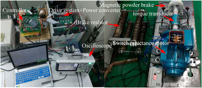
To evaluate the performance of the proposed approach, a simulation and experiment are developed. As shown in Figure 13A, the given current is set as 5A, the embrace is about 0.48, and the motor is operated in the unsaturation state. It is notable that the estimated speed can track the actual speed exactly; the maximum position estimation error is about 0.8°. The experiment result is shown in Figure 13B, the estimated position curve almost coincides with the actual position curve, in which the estimated error is about 1.1°.
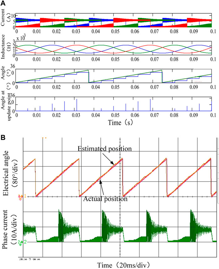
FIGURE 13. (A)The simulation of the inductance and position of the motor in the constant speed state (B) experimental results of position estimation under magnetic unsaturation inductance.
Position estimation is affected obviously in the case of variable speed and low speed. The position estimation error slightly increases under these conditions due to the average estimated speed applied in the predictive technology. The simulation and experimental waveforms of the current and estimated position profile are shown in Figure 14. When the motor is running under the magnetic saturation state, the error between the actual position and the calculated position in the simulation is about 3.8°. The improvement is 1.3°compared with the traditional method without considering the saturation effect; the results are very consistent.
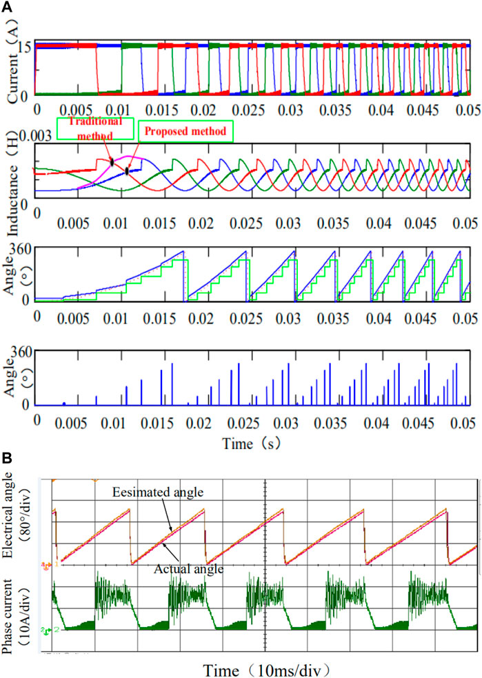
FIGURE 14. (A)The simulation of the inductance and position of the motor in the acceleration state (B) experimental results of position estimation under magnetic saturation inductance.
At the same time, the experiment is accomplished and the motor is operated with 15A, which is within the saturation state, the estimated position coincides with the actual position, of which the maximum error is 1.4°. The conclusion is that the estimated results of speed and position are insensitive to magnetic saturation. The accuracy of the estimated position is improved compared with the traditional method without considering magnetic saturation.
5 Conclusion
The estimation approach encounters implementation issues in the embrace and magnetic saturation operations. This paper proposes a sensorless position estimation strategy considering the embrace and magnetic saturation effect. With a small embrace, three typical intersection of inductance profiles, which are insensitive to the magnetic effect, are employed for sensorless control. Obviously, the position of these intersections is greatly different with that of a large embrace when the motor is operated at the saturation load condition. In this case, the relationship of the intersection position and the saturation current is investigated and presented with the saturation load condition. High accuracy of the estimated rotor position is achieved with the simulation and experimental results. According to the above analysis, the prominent contribution in this paper is that the suitable sensorless strategy is able to be selected according to the embrace value and the estimated position which is guaranteed even if the motor is operated at the saturation condition.
Data Availability Statement
The original contributions presented in the study are included in the article/Supplementary Material, further inquiries can be directed to the corresponding author.
Author Contributions
CH, HY, JY, LZ and LJ participated in the design of this study, and they both performed the statistical analysis. CH carried out the study and collected important background information. HY, JY, and LZ drafted the manuscript. All authors read and approved the final manuscript. CH, HY and LZ carried out the concepts, design, definition of intellectual content, literature search, data acquisition, data analysis and manuscript preparation. CH, HY and LZ provided assistance for data acquisition, data analysis and statistical analysis. LZ and LJ carried out literature search, data acquisition and manuscript editing. All authors have read and approved the content of the manuscript.
Conflict of Interest
The authors declare that the research was conducted in the absence of any commercial or financial relationships that could be construed as a potential conflict of interest.
Publisher’s Note
All claims expressed in this article are solely those of the authors and do not necessarily represent those of their affiliated organizations, or those of the publisher, the editors and the reviewers. Any product that may be evaluated in this article, or claim that may be made by its manufacturer, is not guaranteed or endorsed by the publisher.
References
Afjei, E., and Nezamabadi, M. M. (2016). A Switched Reluctance Motor for Hybrid Motion Control: Design, Modeling, and Sensorless Drive. IET Electric Power Appl. 10, 498–507.
Barnard, F., Villet, W. T., and Kamper, M. J. (2014). “Hybrid Active-Flux and Arbitrary Injection Position Sensorless Control of Reluctance Synchronous Machines,” in International Symposium on Power Electronics. doi:10.1109/speedam.2014.6871911
Bateman, C. J., Mecrow, B. C., Clothier, A. C., Acarnley, P. P., and Tuftnell, N. D. (2010). Sensorless Operation of an Ultra-high-speed Switched Reluctance Machine. IEEE Trans. Ind. Applicat. 46, 2329–2337. doi:10.1109/tia.2010.2070471
Cai, J., and Deng, Z. (2013). A Sensorless Starting Control Strategy for Switched Reluctance Motor Drives with Current Threshold. Electric Power Components Syst. 41, 1–15. doi:10.1080/15325008.2012.716498
Cai, J., and Deng, Z. (2015). Initial Rotor Position Estimation and Sensorless Control of Srm Based on Coordinate Transformation. IEEE Trans. Instrum. Meas. 64, 1004–1018. doi:10.1109/tim.2014.2364699
Cai, J., and Deng, Z. (2012). Sensorless Control of Switched Reluctance Motor Based on Phase Inductance Vectors. IEEE Trans. Power Electron. 27, 3410–3423. doi:10.1109/TPEL.2011.2179065
Cao, W., Jianhua, Y., Yang, S., Cao, W., and Kirtley, J. L. (2016). “Online Sensorless Position Estimation for Switched Reluctance Motors Using One Current Sensor,” in IEEE Transactions on Power Electronics.
Chang, Y.-T., Cheng, K. W. E., and Ho, S. L. (2015). Type-v Exponential Regression for Online Sensorless Position Estimation of Switched Reluctance Motor. Ieee/asme Trans. Mechatron. 20, 1351–1359. doi:10.1109/tmech.2014.2343978
Cheok, A. D., and Ertugrul, N. (2000). High Robustness and Reliability of Fuzzy Logic Based Position Estimation for Sensorless Switched Reluctance Motor Drives. IEEE Trans. Power Electron. 15, 319–334. doi:10.1109/63.838105
de Araujo Porto Henriques, L. O., Barbosa Rolim, L. G., Issamu Suemitsu, W., Dente, J. A., Costa Branco, P. J., and Costa Branco, P. P. (2011). Development and Experimental Tests of a Simple Neurofuzzy Learning Sensorless Approach for Switched Reluctance Motors. IEEE Trans. Power Electron. 26, 3330–3344. doi:10.1109/tpel.2011.2129597
Elmas, C., Zelaya-De, La., and Parra, H. (1996). “Application of a Full-Order Extended Luenberger Observer for a Position Sensorless Operation of a Switched Reluctance Motor Drive,” in Control Theory & Applications Iee Proceedings. doi:10.1049/ip-cta:19960421
Gao, H., Salmasi, F. R., and Ehsani, M. (2004). Inductance Model-Based Sensorless Control of the Switched Reluctance Motor Drive at Low Speed. IEEE Trans. Power Electron. 19, 1568–1573. doi:10.1109/tpel.2004.836632
Hu, K.-W., Chen, Y.-Y., and Liaw, C.-M. (2015). A Reversible Position Sensorless Controlled Switched-Reluctance Motor Drive with Adaptive and Intuitive Commutation Tunings. IEEE Trans. Power Electron. 30, 3781–3793. doi:10.1109/TPEL.2014.2342877
Huang, S., Wu, Q., Liao, W., Wu, G., and Wei, J. (2021). Adaptive Droop-Based Hierarchical Optimal Voltage Control Scheme for Vsc-Hvdc Connected Offshore Wind Farm. IEEE Trans. Ind. Inform. PP, 1. doi:10.1109/tii.2021.3065375
Hudson, C. A., Lobo, N. S., and Krishnan, R. (2008). Sensorless Control of Single Switch-Based Switched Reluctance Motor Drive Using Neural Network. IEEE Trans. Ind. Electron. 55, 321–329. doi:10.1109/tie.2007.903965
Jakobsen, U., Lu, K., Rasmussen, P. O., Lee, D.-H., and Ahn, J.-W. (2015). Sensorless Control of Low-Cost Single-phase Hybrid Switched Reluctance Motor Drive. IEEE Trans. Ind. Applicat. 51, 2381–2387. doi:10.1109/tia.2014.2385939
Khalil, A., Husain, I., Hossain, S. A., Gopalakrishnan, S., Omekanda, A. M., Lequesne, B., et al. (2005). A Hybrid Sensorless Srm Drive with Eight- and Six-Switch Converter Topologies. IEEE Trans. Ind. Applicat. 41, 1647–1655. doi:10.1109/tia.2005.858304
Krishnamurthy, M., Edrington, C. S., and Fahimi, B. (2006). Prediction of Rotor Position at Standstill and Rotating Shaft Conditions in Switched Reluctance Machines. IEEE Trans. Power Electron. 21, 225–233. doi:10.1109/tpel.2005.861169
Kuai, S. Y., Zhao, S., Heng, F. P., and Cui, X. (2017). Position Sensorless Technology of Switched Reluctance Motor Drives Including Mutual Inductance. Iet Electric Power Appl. 11, 1085–1094. doi:10.1049/iet-epa.2016.0490
Ma, B. Y., Feng, W. S., Liu, T. H., and Chen, C. G. (1998). “Design and Implementation of a Sensorless Switched Reluctance Drive System,” in Proceedings of Second International Conference on Power Electronics and Drive Systems. doi:10.1109/7.722707
Mese, E., and Torrey, D. A. (2002). An Approach for Sensorless Position Estimation for Switched Reluctance Motors Using Artifical Neural Networks. IEEE Trans. Power Electron. 17, 66–75. doi:10.1109/63.988671
Ofori, E., Husain, T., Sozer, Y., and Husain, I. (2015). A Pulse-Injection-Based Sensorless Position Estimation Method for a Switched Reluctance Machine over a Wide Speed Range. IEEE Trans. Ind. Applicat. 51, 3867–3876. doi:10.1109/TIA.2015.2420618
Sato, Y., Murakami, K., and Tsuboi, Y. (2016). Sensorless Torque and Thrust Estimation of a Rotational/linear Two Degrees-Of-freedom Switched Reluctance Motor. IEEE Trans. Magn. 52, 1–4. doi:10.1109/tmag.2016.2536682
Torkaman, H., and Afjei, E. (2013). Sensorless Method for Eccentricity Fault Monitoring and Diagnosis in Switched Reluctance Machines Based on Stator Voltage Signature. IEEE Trans. Magn. 49, 912–920. doi:10.1109/tmag.2012.2213606
Wang, W., and Fahimi, B. (2014). Fault Resilient Strategies for Position Sensorless Methods of Switched Reluctance Motors under Single and Multiphase Fault. IEEE J. Emerg. Sel. Top. Power Electron. 2, 190–200. doi:10.1109/jestpe.2013.2297336
Xu, L., and Wang, C. (2002). “Accurate Rotor Position Detection and Sensorless Control of Srm for Super-high Speed Operation,” in IEEE Transactions on Power Electronics. doi:10.1109/tpel.2002.802196
Yu, C.-H., and Chen, T.-C. (2006). Novel Sensorless Driving Method of Srm with External Rotor Using Impressed Voltage Pulse. IEE Proc. Electr. Power Appl. 153, 632–641. doi:10.1049/ip-epa:20050460
Keywords: switched reluctance motors, position sensorless control, embrace deign, magnetic saturation, high-frequency injection
Citation: Cai H, Han Y, Jiang Y, Luo Z and Liao JL (2022) Flexible Sensorless Position Control of Switched Reluctance Motors considering Both Embrace Design and Magnetic Saturation. Front. Energy Res. 10:822021. doi: 10.3389/fenrg.2022.822021
Received: 25 November 2021; Accepted: 09 March 2022;
Published: 10 May 2022.
Edited by:
Enhua Wang, Beijing Institute of Technology, ChinaReviewed by:
Pedro Melo, Instituto Superior de Engenharia do Porto (ISEP), PortugalCopyright © 2022 Cai, Han, Jiang, Luo and Liao. This is an open-access article distributed under the terms of the Creative Commons Attribution License (CC BY). The use, distribution or reproduction in other forums is permitted, provided the original author(s) and the copyright owner(s) are credited and that the original publication in this journal is cited, in accordance with accepted academic practice. No use, distribution or reproduction is permitted which does not comply with these terms.
*Correspondence: Hui Cai, NDE2ODQ2NzQ5QHFxLmNvbQ==
 Hui Cai
 Yanjie Han
 Yujie Jiang1