- 1Key Laboratory of Smart Grid of Education Ministry, Tianjin University, Tianjin, China
- 2Institute of Electric Power Science and Research, Yunnan Power Grid Corporation, Kunming, China
- 3Faculty of Electric Power Engineering, Kunming University of Science and Technology, Kunming, China
This study researches on the Wudongde hybrid multi-terminal Ultra High-Voltage Direct Current Transmission (UHVDC) project (referred to as Wudongde transmission project in short) from the electromagnetic transient model and simulation and establishes an accurate simulation model of the hybrid multi-terminal UHVDC transmission system with the Power Systems Computer-Aided Design (PSCAD). The hybrid multi-terminal UHVDC transmission system consists of the primary system and the control system. The simulation model of the primary system adopts the parameters of the Wudongde transmission project, and the simulation model of the control system refers to the control system benchmark model of HVDC transmission and 9-terminal DC grid in the International Council on Large Electric Systems (CIGRE). According to the characteristics of the hybrid multi-terminal UHVDC control system, the benchmark model of HVDC transmission and 9-terminal DC grid control system in the CIGRE is modified accordingly, and a simulation model of the control system applicable to the hybrid multi-terminal UHVDC transmission system is established. The accuracy and credibility of the model are verified through the comparison of the recording waveform and the simulating waveform of the steady-state and transient operation. The simulating and field recording waveforms show that the model can accurately simulate the Wudongde transmission project and be used as an effective tool for further studying the electromagnetic transient characteristics of the hybrid multi-terminal UHVDC transmission system.
Introduction
With the implementation of the strategy of “West-East electricity transmission and nationwide interconnection” (Dan et al., 2020; He et al., 2020; Huaqiang et al., 2020; Zehong et al., 2021), several UHVDC projects have been put into operation. UHVDC is an important means to solve the problem of hydropower transmission in Southwest China and the collection and transmission of new energy in Northwest China (Benfeng et al., 2021; Xichun et al., 2021; Yuankang et al., 2021). As the world’s first hybrid multi-terminal UHVDC to solve the outward transmission of hydropower from southwest China, the Wudongde hybrid multi-terminal UHVDC transmission project has been completed and put into operation (Hong et al., 2017), which is a significant breakthrough of UHVDC technology in China. The Wudongde transmission project combines the advantages of traditional high-voltage direct current (HVDC) and flexible DC (Chao et al., 2017; Liu et al., 2020; Li et al., 2021; Muniappan, 2021), with the Kunbei converter station using the Line commutated converter (LCC) and the converter station of Liubei and Longmen using the Modular multilevel converter (MMC) of the Voltage source converter (VSC). Meanwhile, the half-bridge submodule (HBSM) and full-bridge submodule (FBSM) of the MMC are mixed in proportional cascade, which makes the structure of the whole system more complex and the control mode more flexible and brings difficulties to the modeling of the hybrid multi-terminal UHVDC transmission system.
As for DC transmission technologies, there is much research on traditional DC and flexible DC, and the findings are also very rich. On the contrary, there is some research on hybrid multi-terminal DC, although some findings have been made, and they are mainly focusing on topology, control strategy, modeling simulation, and line protection. A few studies have been conducted specifically on hybrid multi-terminal UHVDC (Shan et al., 2018). Shan et al. (2018) studied the topology of the DC system combined with LCC, VSC, overhead line, and cable and proposed a control strategy suitable for the system. Weihuang et al. (2017) designed a control strategy for the hybrid multi-terminal UHVDC to achieve the purpose of coordinating the control of each terminal. Song et al. (2019) and Zhi-da and Qing-song (2019) studied the topology and working principle of the hybrid multi-terminal DC and designed a control strategy suitable for the system. A general small-signal modeling method of hybrid multi-terminal DC is proposed in Anran et al. (2019), and the simulation results are compared in MATLAB and PSCAD. Weihuang et al. (2020) studied the parameters of hybrid multi-terminal HVDC and proposed an optimization method of small-disturbance stability parameters. In Yuansheng et al. (2021), taking the three-section hybrid DC line as the research object, the equivalent circuit of transient traveling wave is derived, and a line protection scheme using traveling wave phase is proposed. Although the above-mentioned references have made some achievements in the study of hybrid multi-terminal DC, it is not entirely for the hybrid multi-terminal UHVDC system, and the parameters of the simulation model are not the actual engineering one, which makes the credibility of the research findings applied to the actual engineering in need for further verification.
The current DC transmission system modeling is mainly studied based on the standard DC test system published by the International Council on Large Electric Systems (CIGRE), but the system lacks a standard simulation model for hybrid DC transmission. In the standard test system, LCC-HVDC is a unipolar structure, the converter valve is composed of one 12-pulse converter, and the output DC voltage level is +500 kV. MMC-HVDC has true and pseudo bipolar structures, the single converter station or unipolar converter valve has only one MMC converter, and the converter bridge arm is composed of a single bridge sub-module. There are two modulation modes for the control of the converter valve: the Pulse Width Modulation (PWM) and the Nearest Level Control (NLC). The output DC voltage level of PWM-MMC-HVDC is ±320 kV, and the output DC voltage level of NLC-MMC-HVDC is ±400 kV. While the output DC voltage of the Wudongde transmission project is ±800 kV. The LCC converter station is composed of double 12-pulse converters in series, and VSC converter station is composed of double MMC converters in series (Yan et al., 2017). It can be seen that the primary system structure of LCC-HVDC and MMC-HVDC in CIGRE is no longer applicable to the hybrid multi-terminal UHVDC transmission system, while the control systems of LCC-HVDC and MMC-HVDC are also different, which needs to be modified on the basis of the standard test system to construct a suitable hybrid multi-terminal UHVDC control system and primary system structure in order to build an accurate simulation model of hybrid multi-terminal UHVDC for the study of electromagnetic transient characteristics (Shen et al., 2017; Shen et al., 2020a; Shen et al., 2020b; Shen and Raksincharoensak, 2021a; Shen and Raksincharoensak, 2021b; Shen et al., 2021a).
This research studies the Wudongde transmission project and establishes an accurate simulation model of the hybrid multi-terminal UHVDC transmission system with the PSCAD/EMTDC simulation software (Yang et al., 2018; Yang et al., 2019a; Yang et al., 2019b; Shen et al., 2021b; Yang et al., 2021a; Yang et al., 2022). Based on the actual parameters of the Wudongde transmission project, a detailed simulation model of the primary system is established. Based on the LCC-HVDC and NLC-MMC-HVDC control systems in CIGRE, the control system is modified, and the necessary additional control links are added to establish a suitable simulation model of the control system. The primary and the control systems are combined to build an accurate simulation model of the hybrid multi-terminal UHVDC transmission system. Compared with the recording waveforms, the simulating waveforms show that the model can simulate the Wudongde transmission project accurately and can be used as an effective tool for further studying the electromagnetic transient characteristics of the hybrid multi-terminated UHVDC transmission system (Yang et al., 2021b; Zhang et al., 2021; Zhu et al., 2020).
Simulation Model of the Primary System
An accurate simulation model of the hybrid multi-terminal UHVDC system directly determines the accuracy of the actual engineering simulation. This study takes the Wudongde transmission project as the research object and establishes the primary equipment simulation model of the hybrid multi-terminal UHVDC transmission system based on the actual design parameters and primary system structure of the Wudongde transmission project, which fully reflects the actual parameters of the primary system of the Wudongde transmission project and has high accuracy and credibility.
Simulation Model of the AC System Module
Simulation Model of the AC System
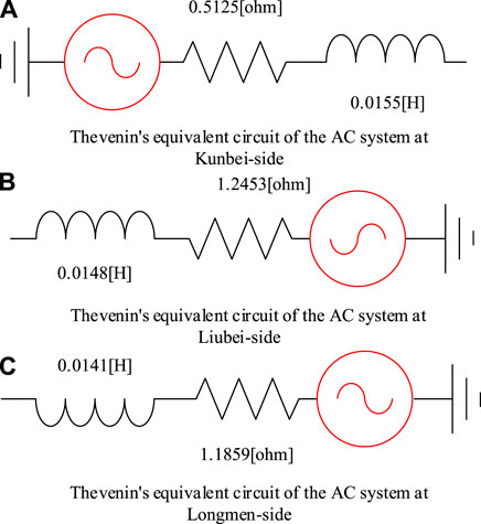
In this study, according to the AC system voltage and maximum three-phase short-circuit current of the Wudongde transmission project, Thevenin’s equivalent models of AC systems at Kunbei-side, Liubei-side, and Longmen-side are established, respectively. The rated voltages of the AC systems at Kunbei-side, Liubei-side, and Longmen-side are 535, 525, and 500 kV, respectively, and the maximum three-phase short-circuit currents of the AC systems at all three sides are 63 kA. The maximum short-circuit capacity and Thevenin’s equivalent impedance of the AC systems can be calculated according to the following equations:
SC is the maximum short-circuit capacity of the AC system, U is the rated voltage of the converter bus, I is the maximum three-phase short-circuit current of the AC system, and Zst is Thevenin’s equivalent impedance of the AC system. The parameters of the AC system at each terminal of the Wudongde transmission project are brought in to obtain the equivalent parameters of the AC system at each terminal. Simultaneously, the simulation models established by the AC system on the Kunbei-side, Liubei-side, and Longmen-side are shown in Figure 1.
Simulation Model of the AC Filter
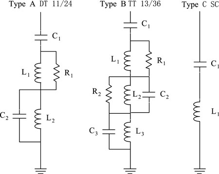
As LCC converter is adopted at the Kunbei converter station, in order to ensure that reactive power compensation and harmonic level meet engineering requirements, six groups of type A filters DT 11/24, six groups of type B filters TT 3/13/36, and eight groups of type C filters SC are configured, with a total of 20 groups. The wiring diagrams of types A, B, and C of filters are shown in Figure 2. The 20 groups are divided into four groups. The grouping scheme is as follows:
For Liubei and Longmen converter stations, MMC converter is adopted, and the harmonic content of the introduced system is lower than the standard of configuring AC filter (Zheng, 2016). At the same time, an MMC converter can be used as a STATCOM device, capable of emitting and absorbing reactive power. Therefore, the AC filter only needs to be configured at the Kunbei converter station.
Simulation Model of the Converter Station Module
The converter station module contains converter transformer, converter valve, smoothing reactor, DC filter, current limiting reactor, and converter valve control module, whose function is to realize the mutual conversion of AC and DC, which is the core part of the whole DC transmission system, among which the simulation model of converter valve control module is described in the next section.
Simulation Model of the Converter Transformer
The parameters of the converter transformer of the Wudongde transmission project are shown in Table 1. It shows the parameters of a single-phase two-winding transformer (Lingyun et al., 2018). The actual project usually combines three single-phase transformers to form a three-phase transformer, and the simulation model can use a three-phase two-winding transformer instead, but the capacity is changed. The capacity of the Kunbei-side becomes 1,217.4 MVA, that of Liubei-side becomes 870 MVA, and that of Longmen-side becomes 1440 MVA, while other parameters and wiring methods remain unchanged.
Simulation Model of the Converter Valve
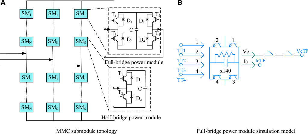
The rated voltage of the hybrid multi-terminal UHVDC is ±800 kV. In order to make the output voltage of the converter station reach the design value, two 12-pulse converter units are connected in series to form the simulation model of the unipolar converter valve of the Kunbei converter station, two LCCs are connected in series to form the high-low valve, each converter unit is subjected to 400kV, and the voltage is distributed according to (400 + 400) kV. Two MMC converter units are connected in series to form a simulation model of unipolar converter valve at the Liubei and Longmen converter stations. Two MMCs are connected in series to form a high-low valve, a single MCC converter is subjected to 400 kV, and the series voltage is distributed according to (400 + 400) kV. The single MMC is composed of half-bridge submodules and full-bridge submodules in a mixed cascade of 3:7 to form each bridge arm, with a total of 200 submodules conducting at any moment in the upper and lower bridge arms with some redundancy. The output voltage of the single MMC converter is maintained at 400 kV. The sub-module topology is shown in Figure 3A, and the simulation model of the full-bridge sub-module is shown in Figure 3B.
Simulation Model of DC Filter
Among the three converter stations, the MMC voltage source converter is adopted in Liubei and Longmen converter station, and the harmonic content of output direct flow satisfies the specifications. Therefore, a DC filter is not required, but only in the Kunbei converter station. The Kunbei converter station is configured with unipolar two groups of three tuned filters, and its parameters are as follows:
Simulation Model of Smoothing Reactor and Current Limiting Reactor
Two 75 mH smoothing reactors are installed at the unipolar neutral bus and DC pole, respectively, in the Kunbei Converter Station, with a total of four.
One 200 mH current limiting reactor is installed at the unipolar neutral bus of the Liubei converter station, and two 50 mH current limiting reactors are installed at the DC pole line, with a total of three. One 150 mH current limiting reactor is installed at each unipolar neutral bus and DC pole at Longmen converter station, two in total.
Simulation Model of Transmission Line Module
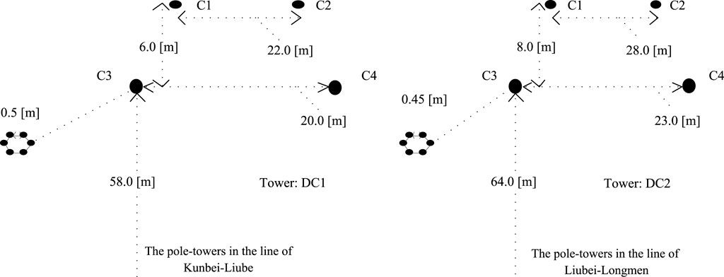
Wudongde transmission project starts from Kunbei converter station in Kunming, Yunnan province in the west, to the Liubei converter station in Liuzhou, Guangxi province, and Longmen converter station in Huizhou, Guangdong province in the East, with a total length of 1,489 km, of which the length of the Kunbei-Liubei section is 932 km, and the average soil resistivity along the line is 1750 Ω
Control System Modeling
A CIGRE standard HVDC test system has been published, which is an effective and convenient research tool to study HVDC technology. At present, two types of simulation models of LCC-HVDC and VSC-HVDC are provided in the system. Among them, the MMC-HVDC control system of VSC-HVDC has two modulation modes of PWM and NLC to choose from. However, CIGRE does not provide a standard HVDC model for mixing the LCC converter station with VSC converter stations. Moreover, the Wudongde transmission project adopts constant DC and constant α control at the Kunbei-side, constant active and reactive power control at the Liubei-side, and constant DC voltage and reactive power control at the Longmen-side.
Therefore, based on the LCC-HVDC and NLC-MMC-HVDC control systems in CIGRE, this study establishes a simulation model of the control system suitable for hybrid multi-terminal UHVDC transmission by making necessary modifications to the control system and adding some auxiliary control links.
Control System Model of LCC Converter Station
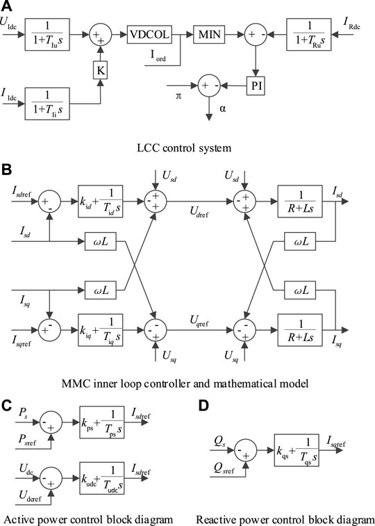
The LCC-HVDC in CIGRE is a unipolar system. The converter station is connected in series with two 6-pulse converters to form a single 12-pulse converter, with rated DC, voltage, and power of 2 kA, 500 kV, and 1000 MW, respectively. While the Wudongde transmission project is a bipolar system. The Kunbei converter station adopts the LCC converter, and the single-pole consists of high-low valves through two 12-pulse converter in series. The output rated DC, voltage, and power are 5 kA, 800 kV, and 4000 MW, respectively (Jingjing et al., 2018). The output of voltage, DC, and DC power of the whole converter station is ±800 kV DC, ±5 kA, and 8000 MW, respectively. It can be seen that the existing control system in CIGRE cannot meet the actual needs of the project. For this reason, the standard control system of LCC-HVDC is modified to meet the control requirements of the converter valve in the Kunbei converter station, and the modified control system is shown in Figure 5A.
As can be seen from Figure 5A, the main modifications are as follows:
1) The same measured voltage and current values are selected as the control signals for the unipolar converter valve at the Kunbei converter station.
2) The same triggering angle α generated by constant current control is used to control the conduction of all converters of the unipolar converter valve simultaneously.
3) The measurement links at the Kunbei-side and Longmen-side are simulated with the first-order inertial link. The measured current gain of the Kunbei-side is modified to 0.2, and the measured current and voltage gains of the Longmen-side are modified to 0.32 and 0.00125, respectively. Then, the measured current of the Longmen-side after the first-order inertia link is multiplied by 0.04 and adds with the measured voltage of the Longmen-side after the first-order inertia link as the voltage value at the midpoint of the line, which is converted to current value after the limiting link, and the inertia time constant is not modified.
In addition, the unipolar converter valve adds a forced phase-shifting and unlocking control module to realize the purpose of unlocking conduction after establishing a stable DC voltage at the MMC side and forced phase-shifting after DC system fault. The control models of the positive electrode and the negative electrode are basically the same. After multiplying the measured voltage at the gantry side by −1, it can be used as the input value of the measured voltage of the negative electrode control system at the Kunbei-side.
Control System Model of MMC
The NLC-MMC-HVDC in CIGRE has both true and pseudo-bipolar structures. However, a single converter station or unipolar converter valve has only one MMC converter, and the output rated DC voltage is ±400 kV. In contrast, the Wudongde transmission project is a true bipolar multi-terminal system, with MMC converters at Liubei and Longmen converter station and a unipolar converter valve with two MMCs connected in series to form a high-low valve. The output rated DC, voltage, and power are ±1.875 kA, ±800 kV, and 3000 MW at the Liubei converter station and ±3.125 kA, ±800 kV, and 5000 MW at the Longmen converter station. In addition, the MMC converter of the standard flexible DC test system in CIGRE has a single bridge structure, while the MMC converter of the Wudongde transmission project has a hybrid bridge structure, which shows that the existing control system cannot meet the actual needs of the project. Therefore, the standard control system of NLC-MMC-HVDC is modified to meet the converter valve control requirements of the Liubei and Longmen converter station. The MMC converter has two kinds of controllers, the outer loop and the inner loop (Ligang et al., 2017), and the combination of the two constitutes the control system of the MMC. The inner loop controller and the mathematical model are shown in Figure 5B, and the outer loop controller is shown in Figure 5C and Figure 5D.
Based on the MMC converter control system, the main modifications are as follows:
1) The same measured current value and the measured voltage values of both high-low valves are selected as the control signals for the unipolar converter valves at the Liubei and Longmen converter stations.
2) The same active or reactive command value is adopted as the input command signal for both unipolar high-low valves.
3) An unlocking module on failure is added to achieve transient fault self-clearing capability for the full-bridge submodule.
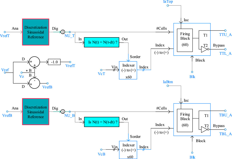
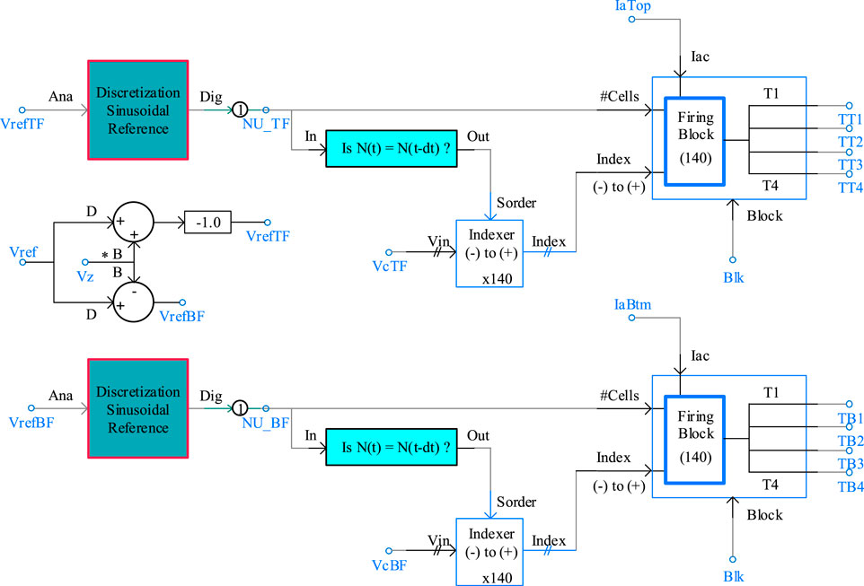
Moreover, the MMC submodule of the Wudongde transmission project adopts a hybrid bridge structure, so the full-bridge submodule is added to the half-bridge type MMC to form a hybrid bridge structure, using the same measured signal as the input signal of the full-bridge and half-bridge submodule control systems, the output signal of the half-bridge submodule control system controls the on/off of the half-bridge submodule, and the output signal of the full-bridge submodule control system controls the on/off of the full-bridge module. The simulation models of the half-bridge submodule and the full-bridge submodule control system are shown in Figure 6 and Figure 7.
Simulation Model of Hybrid Multi-Terminal UHVDC
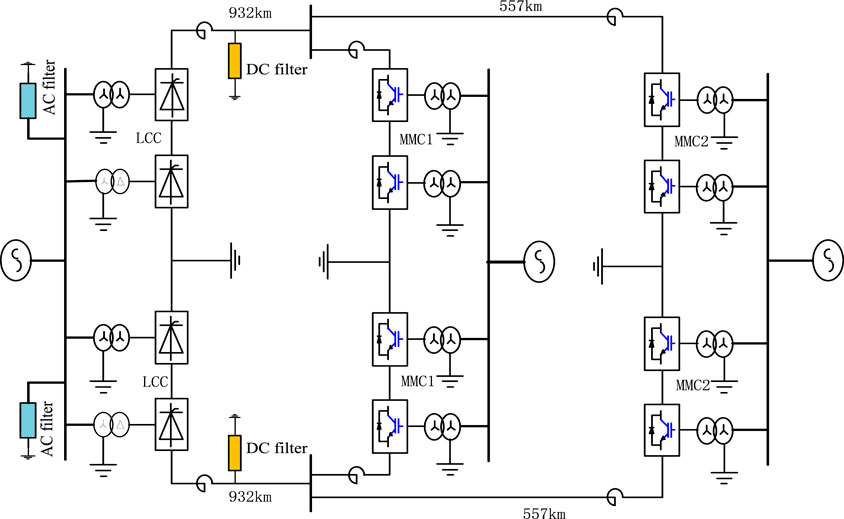
According to the parameters, the main wiring diagram, the simulation model of each component, and the control system of the Wudongde transmission project, the simulation model of the Wudongde transmission system is established as shown in Figure 8.
The Wudongde transmission project is designed with a rated voltage of ±800 kV, the Kunbei converter station is designed to output ±5 kA rated current and 8000 MW rated DC power, the Liubei converter station is designed to output ±1.875 kA rated current and 3000 MW rated DC power, and the Longmen converter station is designed to output ±3.125 kA rated current and 5000 MW rated DC power. The Kunbei-side is controlled with constant current, the Liubei-side is controlled with constant active and reactive power, and the Longmen-side is controlled with constant DC voltage and constant reactive power. The rated voltage of the AC system is 535, 525, and 500 kV at Kunbei, Liubei, and Longmen converter station, respectively, and the maximum short-circuit current of all three phases is 63 kA. Four large groups of AC filters are installed at the AC bus of the Kunbei converter station, two groups of triple tuned filters at the positive and negative electrode outlet of the converter station, and two sets of 75 mH smoothing reactors are installed at the positive and negative neutral bus and the DC pole, respectively. At the positive and negative neutral bus of the Liubei converter station, one 200 mH current limiting reactor is installed, respectively, and two 50 mH current limiting reactors are installed, respectively, at the DC pole. A 150 mH current limiting reactor is installed at the positive and negative neutral bus and DC pole, respectively, in the Longmen converter station. The transformer adopts a three-phase double-winding structure, with the capacity of a single set of 1,217.4 MVA at the Kunbei-side, wired in two ways, Y0/Y and Y0/△; 870 MVA at the Liubei-side, wired in Y0/Y; and 1440 MVA at the Longmen-side, wired in Y0/Y. The unipolar converter valve of the Kunbei converter station uses two 12-pulse LCC converters connecting in series to form a high-low valve, the voltage distribution is according to (400 + 400) kV, the two MMC converter units are connecting in series to form the unipolar converter valve of the Liubei converter station and Longmen converter station, and the voltage distribution is according to (400 + 400) kV. The MMC converter valve bridge arm is composed of a half-bridge submodule and full-bridge submodule in a mixed cascade ratio of 3:7. The upper and lower bridge arms are connected to 200 submodules at any time with certain redundancy, and the output voltage of a single converter is maintained at 400 kV. The total length of the Wudongde transmission project is 1,489 km, of which the Kunming–Liuzhou section is 932 km, the average soil resistivity along the line is 1750 Ω
Simulation Running
In this study, a simulation model of hybrid multi-terminal UHVDC transmission is established in PSCAD/EMTDC with the Wudongde transmission project as the object. Under the full-voltage ground return operation mode, steady-state simulation experiments are conducted for three basic DC operation modes, namely, positive, negative, and bipolar operation, and the transient process of faults occurring on the DC line during bipolar operation is simulated to verify the accuracy and credibility of the simulation model built in this study, in which the measurement points are located at the outlet of the smoothing reactor of Kunbei converter station and the outlet of the current limiting reactor of Liubei and Longmen converter station outlet.
Steady-State Operation
Simulation of Positive Full-Voltage Ground Return Operation
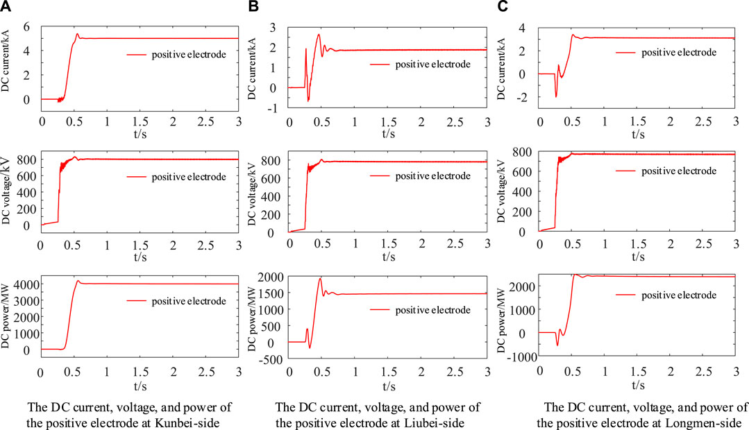
The DC, voltage, and power waveforms at the outlet of the positive smoothing reactor of the Kunbei converter station and the outlet of the positive limit current reactor of the Liubei and Longmen converter station under the positive full-voltage ground return operation are shown in Figure 9.
From Figure 9, it can be seen that the DC, voltage, and power at the outlet of the smoothing reactor of Kunbei converter station are +5 kA, +800 kV, and 4000 MW, respectively; the DC, voltage, and power at the outlet of the current limiting reactor at Liubei converter station are around +1.875 kA, +780 kV, and 1445 MW, respectively; and the DC at the outlet of the current limiting reactor at the Longmen converter station are around +3.125 kA, +765 kV, and 2375 MW, respectively. The DC, voltage, and power at the Kunbei-side are consistent with the design rating of the Wudongde transmission project, and the DC at the Liubei-side and Longmen-side are consistent with the design rating of the project, while the DC voltage and power are lower than the design rating, which is caused by the transmission line losses. It can be seen that the output DC, voltage, and power of the hybrid multi-terminal UHVDC transmission system established in this study for positive full-voltage operation are basically the same as the design values of rated current, voltage, and power during the positive operation of the Wudongde transmission project.
Simulation of Negative Ground Return Operation Mode in Full Voltage
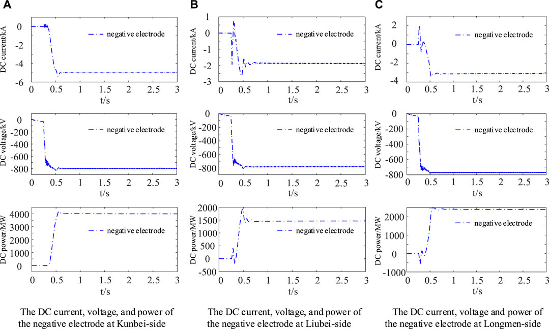
Under the negative ground return operation mode in full voltage, the DC, voltage, and power waveforms at the outlet of the negative smoothing reactor of the Kunbei converter station, the DC, voltage, and power waveforms at the outlet of the negative limiting current reactor of the Liubei converter station and the DC, voltage, and power waveforms at the outlet of the negative limiting current reactor of Longmen converter station are shown in Figure 10.
From Figure 10, it can be seen that the DC, voltage, and power at the outlet of the smoothing reactor at Kunbei converter station are −5 kA, −800 kV, and 4000 MW, respectively; the DC, voltage, and power at the outlet of the current limiting reactor at the Liubei converter station are around −1.875 kA, −780 kV, and 1445 MW, respectively; and the DC, voltage, and power at the outlet of the current limiting reactor at the Longmen converter station are around −3.125 kA, −765 kV, and 2375 MW, respectively. The DC, voltage, and power at the Kunbei-side are highly consistent with the design rating of the Wudongde transmission project; the DC at the Liubei-side and Longmen-side are consistent with the design rating of the Wudongde transmission project; and the DC voltage and power are lower than the design rating, which is caused by the transmission line losses. It can be seen that the output DC, voltage, and power of the hybrid multi-terminal UHVDC transmission system established in this study for negative full-voltage operation are basically the same as the design values of rated current, voltage, and power for negative operation of the Wudongde transmission project.
Simulation of Bipolar Ground Return Operation Mode in Full Voltage
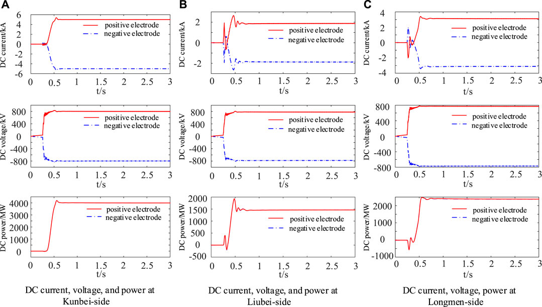
The DC, voltage, and power waveforms at the outlet of the smoothing reactors of the positive electrode and the negative electrode at the Kunbei converter station; the DC, voltage, and power waveforms at the outlet of the limiting current reactors of the positive electrode and the negative electrode at the Liubei converter station; and the DC, voltage, and power waveforms at the outlet of the limiting current reactors of the positive electrode and the negative electrode at the Longmen converter station under the bipolar ground return operation mode in full voltage are shown in Figure 11.
From Figure 11, it can be seen that the DC, voltage, and power at the outlet of the smoothing current reactor of the positive electrode at the Kunbei converter station are +5 kA, +800 kV, and 4000 MW, respectively, and the DC, voltage, and power at the outlet of the smoothing current reactor of the negative electrode are −5 kA, −800 kV, and 4000 MW, respectively. The DC, voltage, and power at the outlet of the limiting reactor of the positive electrode at the Liubei converter station are around +1.875 kA, +780 kV, and 1445 MW, respectively. The DC, voltage, and power at the outlet of the limiting reactor of the negative electrode are around −1.875 kA, −780 kV, and 1445 MW, respectively. The DC, voltage, and power at the outlet of the limiting reactor of the positive electrode at the Longmen converter station are around +3.125 kA, +765 kV, and 2375 MW, respectively. The DC, voltage, and power at the outlet of the limiting reactor of the negative electrode are around −3.125 kA, −765 kV, and 2375 MW, respectively. The DC, voltages, and powers of the positive electrode and the negative electrode at the Kunbei-side are consistent with the design rating of the Wudongde transmission project; the DC of the positive electrode and the negative electrode at the Liubei-side and Longmen-side are consistent with the design rating of the Wudongde transmission project; and the DC voltages and powers are lower than the design rating, which is caused by the transmission line losses. It can be seen that the output DC, voltage, and power of the bipolar operation in full voltage of the hybrid multi-terminal UHVDC transmission system established in this study are basically the same as the design rated current, voltage, and power of the bipolar operation in full-voltage of the Wudongde transmission project.
Waveform Comparison in Steady-State Operation
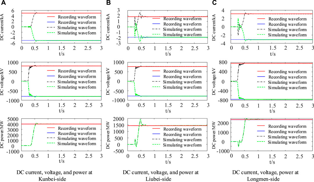
The simulating and recording waveforms of the Wudongde transmission project are shown in Figure 12 under the operations of bipolar ground return in full voltage.
From Figure 12, it can be seen that the output DC, voltage, and power simulation waveforms at the outlet of the smoothing reactor of the Kunbei converter station of the hybrid multi-terminal UHVDC transmission system are highly consistent with the recording waveforms under the operations of bipolar ground return in full voltage. Moreover, the output DC, voltage, and power simulating waveforms at the outlet of the limiting reactor of the Liubei and Longmen converter stations are highly consistent with the recording waveforms, which shows that the simulation model of the hybrid multi-terminal UHVDC transmission system built in this study can accurately simulate the steady-state operation of the Wudongde DC transmission project.
Waveform Comparison of Transient Operation
Overhead DC transmission lines are prone to failure due to complex terrain and climate, and transient response is an important means to test the accuracy of the simulation model. Therefore, taking the grounding fault of the transmission line as an example, this study compared the simulating waveforms with the actual recording waveforms to further verify the accuracy and credibility of the simulation model of the hybrid multi-terminated UHVDC transmission system built in this study.
Midpoint Fault of the Negative Electrode of the DC Line From Liuzhou to Longmen Converter Station
Assume that the grounding fault of the negative electrode occurs at the midpoint of the Liuzhou–Longmen transmission line, with the grounding resistance of 0.4 Ω and the fault duration of 0.1 s. A comparison of the simulating and recording waveforms of the DC and voltage is shown in Figure 13.
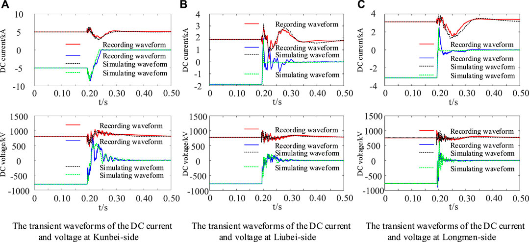
FIGURE 13. Comparison of transient waveforms of negative electrode midpoint faults in the DC line from Liuzhou to Longmen.
From Figure 13, it can be seen that when a grounding fault occurs at the negative electrode midpoint of the transmission line of the Wudongde transmission project, the DC at the fault pole of the Kunbei-side increases rapidly to 1.7 times the rated value and then gradually decreases to 0. The DC at the non-fault pole increases slightly, fluctuates sharply, and then tends to normal values. The fault pole voltage rapidly decreases, increases anyway, and then gradually decreases to 0, and the non-fault pole voltage fluctuates violently and then tends to normal value. At the Liubei-side, the fault pole DC rapidly decreases and increases in reverse to near the rated value and then gradually decreases to 0. The non-fault pole current fluctuates violently and then gradually tends to normal value. The fault pole voltage decreases rapidly and then gradually tends to 0, and the non-fault pole voltage fluctuates and then gradually tends to the normal value. The fault pole DC at the Longmen-side decreases rapidly and increases in reverse to near the rated value and then gradually decreases to 0. The non-fault pole current fluctuates violently and then gradually tends to the normal value. The fault pole voltage decreases rapidly and then gradually tends to 0. The non-fault pole voltage fluctuates and then gradually tends to the normal value. The trend of the simulating waveform at the three terminals after the fault is basically the same as that of the recording waveform, especially in the first 5 ms after the fault and after a period of time. The incomplete consistency between the recording and the simulating waveforms after the fault is caused by the difference in control strategies between the CIGRE standard control system and the actual engineering control system during the fault.
Fault at 25% of the Positive Electrode of the DC Transmission Line From Liuzhou to Longmen Converter Station
Assume that the grounding fault occurs at 25% of the positive electrode of the transmission line from Liuzhou to Longmen, with a ground resistance of 0.4 Ω and a fault duration of 0.1 s. A comparison of the simulating and recording waveforms of the DC and voltage is shown in Figure 14.
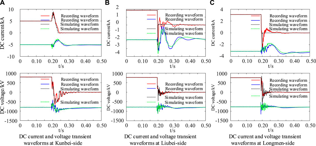
FIGURE 14. Comparison of transient waveforms at the positive electrode 25% of the DC line from Liuzhou to Longmen.
From Figure 14, it can be seen that when a ground fault occurs at the positive electrode of the transmission line of the Wudongde transmission project, the DC at the fault pole of the Kunbei-side increases rapidly to 1.7 times the rated value and then gradually decreases to 0. The DC at the non-fault pole fluctuates after a slight increase and then tends to the normal value. The voltage at the fault pole rapidly decreases and increases anyway and then gradually decreases to 0. The non-fault pole voltage fluctuates drastically and then tends to a normal value. The DC of the fault pole at the Liubei-side rapidly decreases, increases in reverse to near the rated value, and then gradually decreases to 0. Non-fault pole current fluctuates violently and then gradually tends to normal value. The fault pole voltage decreases rapidly and then gradually tends to 0. The non-fault pole voltage fluctuates and then gradually tends to the normal value. The fault pole DC of the Longmen-side decreases rapidly, increases in reverse to near the rated value, and then gradually decreases to 0. The non-fault pole current fluctuates violently and then gradually tends to the normal value. The fault pole voltage decreases rapidly and then gradually tends to 0. The non-fault pole voltage fluctuates and then gradually tends to the normal value. The trend of the simulating waveforms at the three terminals after the fault is basically the same as that of the recording waveforms, especially in the first 5 ms after the fault and after a period of time. The incomplete consistency between the recording and simulating waveforms after the fault is caused by the difference in control strategies between the CIGRE standard control system and the actual engineering control system during the fault.
From the above analysis, it can be seen that the DC, voltage, and power of the simulated model of the hybrid multi-terminal UHVDC transmission system in full-voltage operation are consistent with the design rating of the Wudongde transmission project, and the simulating waveforms of DC, voltage, and power in steady-state operation of the model are highly consistent with the actual recording waveforms of the project. The trends of DC and voltage waveforms during the transient process are basically consistent with the trends of recording waveforms, especially in the first 5 ms after the fault occurs, and the simulating and recording waveforms are highly consistent. It can be seen that the simulation model of the hybrid multi-terminal UHVDC transmission system established in this study can accurately simulate the operation of the Wudongde transmission project.
Conclusion
This research studied the Wudongde transmission project. Based on the design parameters and system control mode of the Wudongde transmission project, a detailed simulation model of the hybrid multi-terminal UHVDC transmission system is built by PSCAD/EMTDC. The steady-state operation simulation of the positive electrode, negative electrode, and bipolar DC power transmission is carried out under full-voltage ground return operation mode, and the steady-state simulation waveform of bipolar full-voltage operation mode is compared with the actual recording waveforms. The grounding fault of the DC line is simulated, and the trend of simulating waveform and recording waveform in the transient process is compared. Results show the following:
1) The hybrid multi-terminal UHVDC transmission system simulation model established based on the primary system parameters of the Wudongde transmission project has high accuracy and reliability.
2) The control system model modified based on the HVDC transmission and 9-terminal DC grid control benchmark model of the CIGRE is suitable for the Wudongde transmission project.
3) Under the steady-state operation, the simulating waveforms of the hybrid multi-terminal UHVDC transmission system are highly consistent with those at the same points during the steady-state operation of the actual project.
4) Under transient operation, the trend of simulated waveforms of the hybrid multi-terminal UHVDC transmission system is consistent with the trend of recording waveforms at the Wudongde transmission project.
5) It provides accurate, credible, and effective tools for the study of the electromagnetic transient characteristics in the hybrid multi-terminal UHVDC transmission system.
6) It provides accurate and credible fault simulation data for the research of the hybrid multi-terminal UHVDC transmission line protection.
7) It provides some guidance for the inversion analysis of the Wudongde transmission project accident.
Data Availability Statement
The original contributions presented in the study are included in the article/supplementary material, further inquiries can be directed to the corresponding author.
Author Contributions
CX was responsible for providing ideas, methods, and an experimental platform. SC and YC were responsible for deriving formulas, reviewing, and verifying. WC was responsible for model building, simulation, data analysis, and manuscript writing. GB, JG, and LW wrote sections of the manuscript. All authors participated in the reading and approved the submitted version.
Funding
Research on traveling wave boundary protection of UHV multi-terminal hybrid HVDC transmission lines 52067009.
Conflict of Interest
Author CX is employed by Electric Power Research Institute, Southern Power Grid Yunnan Electric Power Co., Ltd. Author SC works at Kunming University of Science and Technology.
All the authors declare that the research was conducted in the absence of any commercial or financial relationships that could be construed as a potential conflict of interest.
Publisher’s Note
All claims expressed in this article are solely those of the authors and do not necessarily represent those of their affiliated organizations or those of the publisher, the editors, and the reviewers. Any product that may be evaluated in this article, or claim that may be made by its manufacturer, is not guaranteed or endorsed by the publisher.
References
Anran, Z. H. E. N. G., Chunyi, G. U. O., and Zihan, Y. I. N. (2019). Small-signal Modeling Method of Hybrid Multi-Terminal HVDC System[J]. Power Syst. Tech. 43 (11), 4087–4096.
Benfeng, G. A. O., Jian, Y. A. N. G., and Shengli, S. O. N. G. (2021). Coordinated Control Strategy of Hydropower Units for Mitigating Overvoltage of Renewable Energy Generation System Integrated with HVDC[J]. Proc. CSEE, 1–14. [2021-07-11].
Chao, H. O. N. G., Bonian, S. H. I., and Gang, S. U. N. (2017). Fault Characteristics and Control& Protection Strategy of Three-TerminalLCC-MMC Hybrid HVDC Transmission System[J]. Electric Pow er Construction 28 (08), 73–79.
Dan, Y. A. N. G., Jie, D. A. N. G., and Wei, Q. I. U. (2020). Study on Voltage Stability of Hunan Power Grid Integrated with Qi-Shao UHVDC Transmission Line[J]. J. Electric Power Sci. Tech. 35 (06), 163–170.
He, J., Chen, K., Li, M., Luo, Y., Liang, C., and Xu, Y. (2020). Review of protection and Fault Handling for a Flexible DC Grid. Prot. Control. Mod. Power Syst. 5, 15. doi:10.1186/s41601-020-00157-9
Hong, R. A. O., Chao, H. O. N. G., and Baorong, Z. H. O. U. (2017). Study on Improvement of VSC-HVDC at Inverter Side of Wudongde Multi-Terminal UHVDC for the Problem of Centralized Multi-Infeed HVDC[J]. South. Power Syst. Tech. 11 (03), 1–5.
Huaqiang, X. I. O. N. G., Chengxiang, Y. A. N. G., and Liang, M. A. (2020). Electromechanical-electromagnetic Transient Hybrid Simulation of an AC/DC Hybrid Power Grid with UHVDC Hierarchical Connection Mode[J]. Power Syst. Prot. Control. 48 (24), 145–153.
Jingjing, L. I., Weihuang, H. U. A. N. G., and Tao, L. I. U. (2018). Research on Control Strategy of Multi-Terminal Hybrid UHVDC Transmission System[J]. South. Power Syst. Tech. 12 (02), 47–55.
Li, Z., Jiang, W., Abu-Siada, A., Li, Z., Xu, Y., and Liu, S. (2021). Research on a Composite Voltage and Current Measurement Device for HVDC Networks. IEEE Trans. Ind. Electron. 68 (9), 8930–8941. doi:10.1109/tie.2020.3013772
Ligang, Z. H. A. O., Chao, H. O. N. G., and Liang, T. U. (2017). Research and Realization of Electromechanical Transient Modeling of Multi-Terminal DC Transmission System[J]. South. Power Syst. Tech. 11 (07), 26–31.
Lingyun, C. H. E. N., Gaihong, C. H. E. N. G., and Chong, S. H. A. O. (2018). Research on Control Strategy for a 3⁃terminal LCC-MMC HVDC Transmission System[J]. High Voltage Apparatus 54 (07), 146–152.
Liu, Yi., Yang, Nan., and Dong, Bangtian. (2020). Multi-Lateral Participants Decision-Making: A Distribution System Planning Approach with Incomplete Information Game," in IEEE Access 8, 88933–88950.
Muniappan, Mohan. (2021). A Comprehensive Review of DC Fault protection Methods in HVDC Transmission Systems. Prot. Control. Mod. Power Syst. 6, 2. doi:10.1186/s41601-020-00173-9
Shan, L. I. U., Jun, Y. U., and Zhiyuan, H. E. (2018). Research on the Topology and Characteristic of Multi-Terminal HVDC Based on VSC and LCC[J]. Proc. CSEE 38 (10), 2980–2988+3148.
Shen, X., Ouyang, T., Khajorntraidet, C., Li, Y., Li, S., and Zhuang, J. (2021a). Mixture Density Networks-Based Knock Simulator. Ieee/asme Trans. Mechatron., 1. doi:10.1109/TMECH.2021.3059775
Shen, X., Ouyang, T., Yang, N., and Zhuang, J. (2021b). Sample-Based Neural Approximation Approach for Probabilistic Constrained Programs. IEEE Trans. Neural Netw. Learn. Syst., 1–8. doi:10.1109/TNNLS.2021.3102323
Shen, X., and Raksincharoensak, P. (2021b). Pedestrian-Aware Statistical Risk Assessment. IEEE Trans. Intell. Transport. Syst., 1–9. doi:10.1109/TITS.2021.3074522
Shen, X., and Raksincharoensak, P. (2021a). Statistical Models of Near-Accident Event and Pedestrian Behavior at Non-signalized Intersections. J. Appl. Stat., 1–21. doi:10.1080/02664763.2021.1962263
Shen, X., Zhang, X., Ouyang, T., Li, Y., and Raksincharoensak, P. (2020a). Cooperative Comfortable-Driving at Signalized Intersections for Connected and Automated Vehicles. IEEE Robot. Autom. Lett. 5, 6247–6254. doi:10.1109/lra.2020.3014010
Shen, X., Zhang, Y., Sata, K., and Shen, T. (2020b). Gaussian Mixture Model Clustering-Based Knock Threshold Learning in Automotive Engines. Ieee/asme Trans. Mechatron. 25, 2981–2991. doi:10.1109/TMECH.2020.300073210.1109/tmech.2020.3000732
Shen, X., Zhang, Y., Shen, T., and Khajorntraidet, C. (2017). Spark advance Self-Optimization with Knock Probability Threshold for Lean-Burn Operation Mode of SI Engine. Energy 122, 1–10. doi:10.1016/j.energy.2017.01.065
Song, Huang., Yingping, Yi., and Longzhen, Zhu. (2019). Research on Control Strategy of Positive and Negative Bipolar Hybridmulti-Terminal HVDC Transmission System[J]. Electr. Meas. & Instrumentation 56 (13), 51–57+96.
Xichun, W. A. N. G., Chun, L. I. U., and Weifang, L. I. N., (2021) Influence of Wind Turbine Fault Ride through Characteristics on Transient Overvoltage of Large-Scale Wind Power DC Transmission Systems and Parameters Optimization[J].
Weihuang, H. U. A. N. G., Ming, L. I., and Guo Zhu, (2020). Control Parameter Analysis and Optimization Method of Multi-Terminal Hybrid HVDC Transmission System Based on Small Signal Stability[J]. Power Syst. Tech. 44 (08), 2941–2949.
Weihuang, H. U. A. N. G., Shukai, X. U., and Huang Ying, (2017). Steady-State Control Strategy of Multi-Terminal Hybrid UHVDC[J]. South. Power Syst. Tech. 11 (07), 5–10.
Yan, Y. A. N. G., Yong, L. I. N., and We, X. U. (2017). Influnce of Wudongde Multi-Terminal HVDC on Security and Stability of Guangdong Power Grid[J]. Guangdong Electric Power 30 (11), 44–50.
Yang, N., Huang, Y., and Hou, D. (2019a). Adaptive Nonparametric Kernel Density Estimation Approach for Joint Probability Density Function Modeling of Multiple Wind Farms[J]. Energies, 12.
Yang, N., Ye, D., Zhou, Z., Cui, J., Chen, D., and Wang, X. (2018). Research on Modelling and Solution of Stochastic SCUC under AC Power Flow Constraints[J].IET Generation. Transm. Distribution 12 (15), 3618–3625.
Yang, N., Huang, Y., Hou, D., Liu, S., Ye, D., Dong, B., et al. (2019b). Adaptive Nonparametric Kernel Density Estimation Approach for Joint Probability Density Function Modeling of Multiple Wind Farms. Energies 12, 1356. doi:10.3390/en12071356
Yang, N., Liu, S., Deng, Y., and Xing, C. (2021b). An Improved Robust SCUC Approach Considering Multiple Uncertainty and Correlation. IEEJ Trans. Elec Electron. Eng. 16, 21–34. doi:10.1002/tee.23265
Yang, N., Yang, C., Wu, L., Shen, X., Jia, J., Li, Z., et al. (2022). Intelligent Data-Driven Decision-Making Method for Dynamic Multisequence: An E-Seq2Seq-Based SCUC Expert System. IEEE Trans. Ind. Inf. 18, 3126–3137. doi:10.1109/TII.2021.3107406
Yang, N., Yang, C., Xing, C., Ye, D., Jia, J., Chen, D., et al. (2021a). Deep Learning‐based SCUC Decision‐making: An Intelligent Data‐driven Approach with Self‐learning Capabilities. IET Generation Trans. Dist 16, 629–640. doi:10.1049/gtd2.12315
Yuankang, H. E., Ruifeng, L. I. U., and Tian’en, C. H. E. N. (2021). Exploration of Bundled Transaction Model for All Clean Energy Transmission of Qing-Yu UHV DC Project[J]. Electric Power, 1–9. [2021-07-11].
Yuansheng, L. I. A. N. G., Zejie, H. U. A. N. G., and Haifeng, L. I. (2021). Phase Characteristics Based Travelling Wave Protection for Transmission Line of Three-Terminal Hybrid HVDC System. Proc. CSEE 41 (13), 4525–4543.
Zehong, L. I. U., Weimin, M. A., and Wang Shaowu, (2021). Schematic Design of Hybrid Cascaded Ultra HVDC and its Modification in Dynamic Model Experiment[J]. Power Syst. Tech. 45 (03), 1214–1222.
Zhang, L., Xie, Y., Ye, J., Xue, T., Cheng, J., Li, Z., et al. (2021). Intelligent Frequency Control Strategy Based on Reinforcement Learning of Multi-Objective Collaborative Reward Function. Front. Energ. Res., 9. SCI. doi:10.3389/fenrg.2021.760525Frontiers in Energy Research, Early Access
Zhi-da, H. U. A. N. G., and Qing-song, H. U. A. N. G. (2019). Control Strategy of Hybrid Multi-Terminal HVDC Transmission System[J]. Control Eng. China 26 (09), 1738–1744.
Keywords: PSCAD/EMTDC, hybrid multi-terminal UHVDC, CIGRE, accurate simulation model, recording waveform classification
Citation: Xing C, Cai W, Che Y, Bi G, Chen S, Gao J and Wang L (2022) Accurate Modeling Simulation and Experimental Study of Hybrid Multi-Terminal UHVDC Transmission System. Front. Energy Res. 10:820137. doi: 10.3389/fenrg.2022.820137
Received: 22 November 2021; Accepted: 31 January 2022;
Published: 18 March 2022.
Edited by:
Mohd Hasan Ali, University of Memphis, United StatesReviewed by:
Narottam Das, Central Queensland University, AustraliaMehdi Firouzi, Islamic Azad University, Abhar, Iran
Copyright © 2022 Xing, Cai, Che, Bi, Chen, Gao and Wang. This is an open-access article distributed under the terms of the Creative Commons Attribution License (CC BY). The use, distribution or reproduction in other forums is permitted, provided the original author(s) and the copyright owner(s) are credited and that the original publication in this journal is cited, in accordance with accepted academic practice. No use, distribution or reproduction is permitted which does not comply with these terms.
*Correspondence: Shilong Chen, Y2hlbnNoaWxvbmczQDEyNi5jb20=
 Chao Xing
 Wang Cai
 Yanbo Che1