 Makram Mikhaeil
 Matthias Gaderer
 Belal Dawoud
- 1Laboratory of Sorption Processes, Faculty of Mechanical Engineering, East Bavarian Technical University of Applied Sciences (OTH Regensburg), Regensburg, Germany
- 2Mechanical Power Engineering Department, Faculty of Engineering, Menofia University, Shebin-El-Kom, Egypt
- 3Chair Regenerative Energy Systems, TUM Campus Straubing for Biotechnology and Sustainability, Technical University of Munich, Straubing, Germany
This paper introduces the results of an experimental study on the adsorption and desorption kinetics of a commercially available, open-structured asymmetric plate heat exchanger adapted to act as an adsorber/desorber for the application in adsorption heat transformation processes. In addition, a volumetric large temperature jump (V-LTJ) kinetic setup was applied to measure the adsorption and desorption kinetics of a small-scale adsorbent sample prepared dedicatedly to be representative for the adsorbent domain inside the investigated adsorber plate heat exchanger (APHE). All kinetic results of the small-scale adsorbent sample and the APHE were fitted into exponential forms with a single characteristic time constant (τ) with a coefficient of determination (R2) better than 0.9531. A very good matching between the small-scale and full-scale adsorption kinetic measurements was obtained, with an average relative deviation of 12.3% in the obtained τ-values. In addition, the kinetic data of the small-scale adsorbent sample were utilized for estimating the expected specific instantaneous and moving average powers of the evaporator/condenser heat exchanger. The average relative deviation (ARD) between the moving average specific evaporator powers obtained from the small-scale and the full-scale measurements amounts between 5.4 and 15.1%.
Introduction
The adsorber/desorber heat exchanger (Ad-HEx) is the core component of an adsorption system. Realizing highly efficient and durable Ad-HExs is crucial for improving the performance and sustainability of adsorption appliances. Concerning the durability, special care has to be taken regarding the adsorbent material as well as the Ad-HEx construction materials. The cycling stability of the adsorbent material deems to be a crucial requirement for building a sustainable adsorption system. Many adsorbents, which seem highly promising in terms of the adsorption capacity, thermal properties and diffusion characteristics, do suffer from poor hydrothermal cycling (Furukawa et al., 2014). The adsorbent could be in form of loose pellets or consolidated layers, which are mostly produced by dip-coating (Freni et al., 2015a; Oh et al., 2017) or in-situ crystallisation methods (Tatlıer, 1999; Bonaccorsi and Proverbio, 2004; Bonaccorsi et al., 2013). Aside from the mechanical robustness of the adsorbent, the release of some non-desired inert gases could be associated with the dip-coated heat exchangers, upon conducting successive adsorption and desorption processes. It is related to adding some organic binding materials in the coating process of the adsorbents (Freni et al., 2015b). Therefore, the release of non-condensable gases from binder degradation is expected in coated adsorber heat exchangers, leading to a significant reduction of their start of life performance (Sapienza et al., 2016). In-situ crystallization technology has been utilized to produce coating adsorbents without a binder content (Tatlıer, 1999; Bonaccorsi and Proverbio, 2004; Bonaccorsi et al., 2013), however this technology is quite costly and a very limited thickness can only be realized (20–150 microns) (Freni et al., 2015a). To sum up, the adsorbent and its binder system have to be stable. The utilization of loose pellets of adsorbents inside the adsorber heat exchanger is a cheaper alternative to coating or in-situ crystallization. Loose pellets offer a high cycling stability than coatings as well as a high mass transfer area per unit mass.
The construction material of the Ad-HEx has to be highly resistive against corrosion, otherwise inert gases will release out of corrosion reactions resulting in a continuous performance reduction and, on the long term, in destroying the heat exchangers and, consequently, the whole machine (Freni et al., 2015b; Palomba et al., 2017). For small-scale systems dedicated for single and double family houses, where the installation of a vacuum pump for maintenance is not allowed, aluminium has to be avoided as a construction material of the Ad-HEx, as it is subjected to high corrosion rates under pure water vapour, ethanol and methanol atmospheres (Calabrese et al., 2012; Caprì, 2020).
Indeed, the heat transfer characteristics of in-situ crystalized coatings are quite high, leading to high specific power outputs (per kgadsorbent). The limited coating thickness restricts, however, the Coefficient of Performance (COP) and the volumetric storage density (Freni et al., 2015a), if applied as a storage system. On the other hand, making use of loose pellets results in relatively high COP and volumetric storage density with a comparable specific power output (per kgadsorbent) with the binder-coating form, if the pellets’ size and the adsorbent bed thickness are carefully optimized. In (Freni et al., 2007; Gong et al., 2011; Santamaria et al., 2014), it was demonstrated that a layer of loose pellets can provide the same specific power of a coated adsorbent layer. The adsorption dynamics obtained upon conducting adsorption processes on small adsorbent samples in form of monolayer or even multilayers (if n < =4) of adsorbent grains seem to be very promising. Chakraborty et al. (2014) have estimated 5 kW/kg as a specific cooling power of an adsorption chiller having the adsorbent in form of monolayer of loose silica gel pellets.
The adsorbent-adsorbate equilibrium properties, their thermal properties and the mass diffusion characteristics do very much influence the performance of an adsorption appliance. For instance, some MOFs, such as MIL-100 and MIL-101 families, have recently attracted high attention due to their high capacity of water adsorption (Canivet et al., 2014). Graf et al. (2020) have carried out experimental investigations on the dynamics of water adsorption in two different MOFs; namely, MIL-101(Cr) and NH2-MIL-125, and compared them with Siogel, which is characterized by a relatively lower capacity for water adsorption. The study showed that, for the common temperature set 10/30/80°C, MIL-101(Cr) has demonstrated the highest adsorption capacity, but with significantly lower COP (−19%) and volumetric cooling power (−66%) than Siogel. NH2-MIL-125 demonstrated improvement in the COP by 18% compared with Siogel, but with a reduction in the power density by 28%. From the results, they concluded that, the low performance of the two investigated MOFs compared with Siogel are due to the non-matched shape of their isotherms to the specific operating temperatures. Finally, they returned the low efficiency of the MOFs to their lower heat and mass transfer characteristics compared with Siogel.
Concerning the system’s specific power output (SP), adsorber heat exchangers that provide large area for the heat transfer are quite favourable. The finned, flat- and circular-tube heat exchangers attracted, therefore, intensive attention for the application as Ad-HExs, thanks to their relatively large extended heat transfer surface area. Several communications addressed the optimization of the distance between the fins and fin geometry, thickness, and height (Li et al., 2004; Niazmand and Dabzadeh, 2012; Çaǧlar, 2016)However, the effect of the thermal resistance at the fin-root-surface interface on the overall heat transfer coefficient is usually ignored, which should not be the case. Many studies demonstrated that, this interfacial heat transfer resistance governs the heat transfer in the Ad-HEx and, hence, its performance (Hajji & Khalloufi, 1996; Waszkiewicz et al., 2009; Gordeeva et al., 2014; Golparvar et al., 2018). Ilis et al. (2019) investigated numerically the performance of an innovative star-shaped finned tube Ad-HEx. They investigated the effects of the material of construction of their Ad-HEx tube and fins. An almost linear increase of the specific cooling power from 15 to 47 W/kg of silica gel has been reported on upon increasing the aluminium fraction inside the adsorbent coating from zero to 60%. As the SP and the COP are the most important performance indicators of an adsorption appliance, the proper design of the Ad-HEx is a trade-off between the design parameters governing the heat and mass transfer in the adsorbent domain and the thermal capacity of the Ads-HEx (Hong et al., 2015; Bau et al., 2017). In order to achieve a sustainable development, the corrosion potential between some metals (e.g. aluminium) or metal mixtures and the refrigerant (water or ethanol) upon constructing an adsorption system should be taken into account.
So far, the publications dealing with the experimental investigation of small-scale adsorbent samples for predicting the performance of real adsorber heat exchangers showed differences in the adsorption and desorption dynamics of up to a factor of 10 in favour of the small-scale adsorbent samples. Aristov et al. (2012) investigated the adsorption dynamics of small adsorbent samples configured in different layer numbers (n: 1–8) and with different grain sizes. They defined the ratio (S/m), which refers to the heat transfer surface area to the adsorbent dry mass. The ratio (S/m) can be used as a configuration characteristic factor of the adsorbent sample instead of the number of the lose grain layers. From the ratio (S/m) and the average grain size of the sample, the average number of the grain layers composing the sample can be estimated. Although the specific output powers estimated from the experimental data of the investigated samples, if they could be applied in real adsorber heat exchangers, were very promising, the experimental data of the investigated adsorber heat exchangers, which have similar (S/m) and grain size, demonstrated specific output powers 2 to 10 times lower than those estimated from the small samples (Aristov et al., 2012; Aristov, 2020). This quite large difference is returned in (Aristov et al., 2012; Aristov, 2020) to some imperfections in the system components and to some issues related to process organization, such as cycle time, isobaric phase durations, heat and mass recovery and residual air. Beside the attributions reported in (Aristov et al., 2012; Aristov, 2020), those differences in the adsorption dynamics between the small-scale samples and the full-scale adsorbers should be, in addition, dedicatedly investigated from the perspective of the combined heat and mass transfer characteristics prevailing in both small-scale adsorbent sample and the adsorbent domain of the investigated adsorber heat exchanger. Indeed, the equality of S/m ratio between the small-scale adsorbent sample and the investigated adsorber heat exchanger reflects similarity in the heat transfer resistance, however some other aspects should be considered. For example, the fin efficiency of the extended surfaces (fins) shall be accounted for upon estimating the effective surface area. In addition, the vapour transfer area into the adsorbent domain and the interparticle mass transfer resistance of the adsorbate flow through the adsorbent domain of the investigated adsorber heat exchanger should be represented also in the small-scale adsorbent sample. Muttakin et al. (2021) recently presented a comprehensive review of adsorption kinetic models and their application for predicting the adsorption kinetics for various adsorbate-adsorbent pairs. In addition, they discussed in detail the effects of adsorbent particle size and adsorbent layer thickness on adsorption kinetics. Although they reviewed the work of (Aristov et al., 2012; Aristov, 2020), they did not discuss the differences between the full-scale and small-scale adsorption kinetic measurements, reported on in both references.
Dedicatedly designed plate-type heat exchangers made of and brazed with anti-corrosive materials to act as adsorber/desorber heat exchangers has been introduced for the first time by (Dawoud, 2018) and (Mikhaeil et al., 2020). In both references, a plate heat exchanger made of stainless steel and brazed with nickel and dedicatedly designed to act as an adsorber/desorber heat exchanger for the application in adsorption heat transformation processes has been introduced and its dynamic performance has been investigated. The experimental and numerical results demonstrated an enhancement of 310% in the differential water uptake obtained after 300 s of adsorption start compared to extruded aluminium adsorbers, which have been coated with 500 µm of AQSOA-ZO2 (Dawoud, 2007). The extremely reduced volume of the heat transfer fluid (HTF) domain compared to the adsorbent domain, while keeping the uniformity of the temperature distribution over the heat exchanger’s plates are the key design advantages of the introduced APHE (Dawoud, 2018; Mikhaeil et al., 2020), which explain its superior performance. The design of the test frame, in which the small-scale adsorbent grain sample has been tested, has been carried out with a special care to mimic both heat and mass transfer characteristics of the adsorbent domain inside the introduced plate heat exchanger (Mikhaeil et al., 2020).
In this communication, a commercially available, stainless-steel plate heat exchanger produced by Alfa Laval, Sweden, which is basically developed to be applied as a crossflow, gas cooler heat exchanger, has been adapted to work as and adsorber plate heat exchanger (APHE) and is then experimentally investigated in the Laboratory of Sorption Processes (LSP) at OTH Regensburg, Germany. The introduced procedure in (Mikhaeil et al., 2020) is followed to prepare a test frame for the small-scale loose grain sample and to evaluate the matching between the obtained experimental adsorption and desorption kinetic results of the full-scale and small-scale adsorbers. The adsorption and desorption kinetics of the small-scale adsorbent sample are measured in the existing V-LTJ kinetic setup (Dawoud, 2007; Aristov et al., 2008; Dawoud, 2013) at similar operating conditions of the investigated APHE. A slight modification to the introduced thermal response LTJ methodology (Tokarev, 2017), is introduced; namely, to estimate the instantaneous water loading from the measured evaporator or condenser power during adsorption or desorption processes, respectively, rather than carrying out a blind (disconnecting the evaporator from the adsorber) and an active adsorption process and estimate the temporal water uptake from the measured temporal heat of adsorption. The last should be obtained by subtracting the results of the blind experiment from those of the active adsorption experiment (Tokarev, 2017). The results obtained from both small-scale and full-scale investigations at four different operating conditions of adsorption appliances have been compared and discussed in detail. Based on the obtained kinetic results of the small-scale sample, a completely new evaluation methodology has been introduced to estimate the expected evaporator and condenser powers of the full scale adsorber. Such theoretical results have been compared with those obtained upon investigating the full-size APHE.
The “GLX30” Adsorber Plate Heat Exchanger and Its Test Setup
The GLX30 PHE (AlfaLaval, GLX30)1 is the only, nickel-brazed, stainless steel, open-structured PHE available in the market, which produced by AlfaLaval©, Sweden. Formerly, this heat exchanger was obtainable form AIREC©, Sweden under the trade name “Cross-30” PHEx. The PHE, depicted in Figure 1A, comprises a stack of multi, nickel-brazed plate-pairs made of stainless steel 316L. For the sake of mechanical stability of the GLX30 PHE, two flat and thick endplates are integrated to the stack by brazing. The plates composing the heat exchanger channels are embossed (dimpled) in two different forms and arranged together to form a stack of parallel plate-pairs. The plates have up-and-down dimples with different profiles and heights. Such configuration results in two asymmetric and separated domains and each domain comprises several identical subdomains. The volume ratio between the two asymmetric domains of the GLX30 PHE amounts to 1.91. Each plate-pair of the GLX30 confines a subdomain specified for a liquid HTF flow. Each HTF subdomain (HTF channel), existing inside a plate-pair, has an inlet and an outlet port. Those HTF subdomains compose together the HTF domain of the GLX30 PHE.
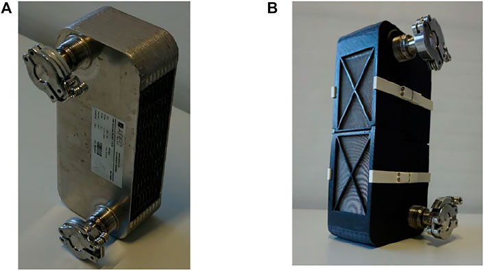
FIGURE 1. The GLX30 adapted as an adsorber heat exchanger (The open sides for vapour flow into/out of the adsorbent domain are covered by a stainless-steel sieve to prevent the loose pellets from falling). (A) Before being filled in with the adsorbent, (B) adapted and filled in with Siogel grains.
The “GLX30” is a crossflow, gas-liquid plate heat exchanger, thus the other domain inside the GLX30 is specified for a gas flow. This means that the GLX30 is not primarily designed to act as an adsorber heat exchanger. However, the open gas domain can be filled in with loose grains of the adsorbent. Using a suitable stainless-steel sieve on each side for preventing the adsorbent grains from falling out, the GLX30 PHE can act as an adsorber heat exchanger. Figure 1B shoe adapted GLX30 PHE to work as an adsorber plate heat exchanger (APHE). The spaces (gaps) existing between the successive plate-pairs are utilized as an adsorbent domain and filled with 842 g of the loose microporous Siogel (Oker Chemie, Germany) in the grain size range of 0.71–1.0 mm. Table 1 illustrates more specifications of the GLX30 PHE.
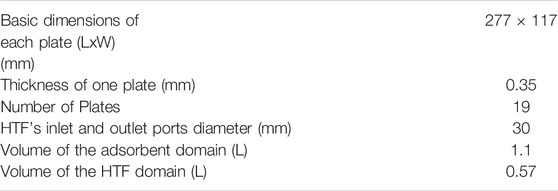
TABLE 1. Specifications of the GLX30 PHE.
A special test setup has been established to investigate the adsorption and desorption kinetics of the full-scale GLX30 APHE. The setup, depicted schematically in Figure 2, consists mainly of two compartments, the evaporator/condenser unit and adsorber/desorber unit. The evaporator/condenser unit is a double helical tube heat exchanger fixed inside a vacuum tight chamber made of stainless steel and equipped with inlet and outlet ports for the internal double helical tube HEx. Two temperature sensors are mounted on the inlet and outlet ports of the evaporator/condenser unit for measuring the temperature of HTF passing through the internal helical tube heat exchanger. In addition, a flow rate sensor is adapted to measure the volume flow rate of the HTF inside the evaporator/condenser (
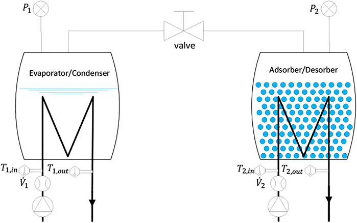
FIGURE 2. Schematic drawing of the test setup.
For an effective evaporation operation, a falling film evaporator concept has been developed and realized inside the evaporator/condenser chamber. The adsorber/desorber unit is another vacuum tight chamber made of stainless steel, in which the adapted APHE (Figure 1B) is mounted. The chamber is equipped with side connection ports for feeding the internally mounted APHE with the HTF. Two temperature sensors are mounted on the connection ports to measure the temperature of the HTF at the inlet and outlet of the APHE. The volume flow rate of the HTF inside the adsorber/desorber loop (
Both chambers are equipped, at the top part, with vacuum-tight ports, for connecting vacuum pressure transducers (P1 & P2), and 50 mm diameter ports, to which, central vacuum flanges are welded, to enable connecting the two chambers together through a vacuum tight tube having a vacuum gate valve of DN50. Figure 3 illustrates the realized test setup for the APHE in the Laboratory of Sorption Processes (LSP) of OTH-Regensburg, Germany.
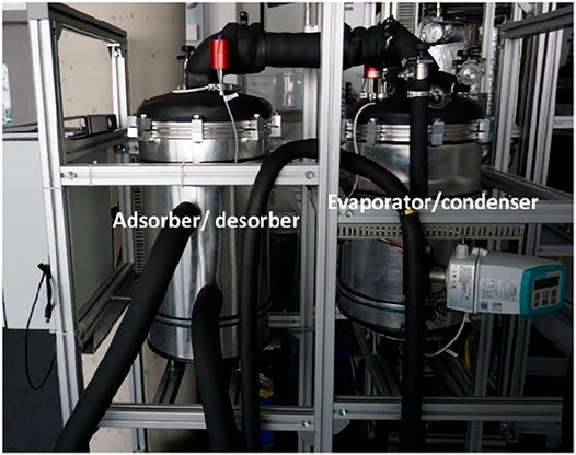
FIGURE 3. Realized test setup for investigating the APHE at the LSP of OTH-Regensburg, Germany.
A dedicated hydraulic setup has been also developed, which comprises two separated hydraulic circuits, a primary and a secondary circuit. The primary circuit feeds the adsorber/desorber heat exchanger, whereas the secondary one feeds the evaporator/condenser heat exchanger. A high precision measuring and control system has been established, which is monitored and interfaced via a specially developed LabVIEW code. Via the LabVIEW code, the desired temperature and flow rate of the HTF on each hydraulic circuit can be realized. The type and accuracy of the individual sensors applied for measuring the pressure of the refrigerant vapour in both vessels and the inlet and outlet temperatures and flow rate of the HTFs passing through the units are listed in Supplementary Table S1. The measurements have been carried out at the following values for evaporator (
The water uptake obtained upon conducting LTJ adsorption and desorption processes on the investigated APHE has not been measured explicitly. Instead, the time integration of the instantaneous power of the evaporator or condenser have been applied to estimate the total amount of refrigerant evaporated from the evaporator and adsorbed in the adsorber or the amount water vapour desorbed from the desorber and condensed in the condenser during each adsorption or desorption process, respectively. First, the measurements of the volume flow rate of HTF passing through the evaporator/condenser (
The instantaneous specific (per kg of adsorbent) evaporator/condenser power (
where
The time integration of the instantaneous evaporator/condenser power (
Where,
The water uptake obtained in an adsorption process (
Where,
The specific moving average evaporation/condensation power obtained in an adsorption/desorption process (
The uncertainty analysis of the water uptake estimation, the instantaneous and moving average evaporator and condenser power measurements are presented in the Supplementary Material.
Small-Scale Adsorbent Sample Preparation and Testing in a V-LTJ Kinetic Setup
The dimensions of the test frame for the small-scale adsorbent sample have been determined according to the described methodology in (Mikhaeil et al., 2020). The mass transfer characteristic length, which is equal to the diffusion path length of the refrigerant vapour from each side of the adsorbent domain up to the symmetrical axis for the mass transfer equals half the width of each plate; namely 58.5 mm. As each adsorbent domain is surrounded by two HTF domains, the heat transfer characteristic length, which equals the height of the adsorbent inside the test frame shall equal to half of the gap between each two successive plate pairs constituting the HTF-domains. Due to the dimple structure of the GLX30, the gap size is not uniform over the plate area. In order to account for the worst case, the maximum gap dimension (6 mm) is considered to estimate the height of the adsorbent volume inside the test frame. Accordingly, the height of the adsorbent volume inside the test frame is estimated to 3 mm.
As the maximum expected differential water uptake from the utilized microporous silica gel (Siogel of Oker Chemie, Germany) under the tested operating conditions does not excess 25 g/100g, the mass of the samples that will be tested in the small-scale sorption kinetics’ setup is limited to 320 mg to guarantee the adsorption or desorption measurements to be carried out under quasi-isobaric (∆p < 2 mbar) conditions (Aristov et al., 2008). Based on this limitation of the sample mass, and accordingly its volume inside the test frame, the width of the sample has been determined to 3 mm. Figure 4A shows the configuration of the test frame and Figure 4B shows the final fabricated test frame filled with Siogel and placed on the sample holder inside the measuring cell of the kinetics’ setup.
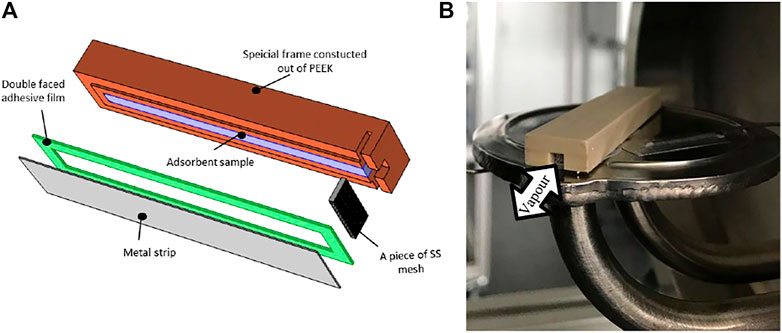
FIGURE 4. Test frame prepared to realize small-scale representative adsorbent sample; (A) test frame construction, (B) final fabricated test frame filled with Siogel and placed on the sample holder of the kinetics’ setup measuring cell.
The test frame, constructed and built out of PEEK (PolyEther Ether Ketone) for its low thermal conductivity and negligible outgassing characteristics, shall also enable the refrigerant vapour (adsorbate) to enter/leave the adsorbent sample placed inside it from a small slot, at which a piece of a stainless-steel sieve is installed to prevent the grains from falling out from the frame. As depicted in Figure 4B, the slot shall be existing in one side of the test frame allowing the refrigerant vapour to diffuse in longitudinal direction through the adsorbent sample. As depicted in Figure 4A, the back side of the test frame is closed as it represents the mass transfer symmetric axis in the middle plan of each adsorbent domain (Mikhaeil et al., 2020). At the downside of the PEEK construction a metal strip (stainless steel substrate) of 0.3 mm thickness is mounted to allow the heat transfer between the sample and the holder surface inside the measuring cell of the kinetic setup. The PEEK test frame and the stainless-steel substrate are sealed together by a special double-sided adhesive film after inserting the adsorbent grains.
The details of the V-LTJ kinetic setup, the experimental procedure and the evaluation of the instantaneous water uptake can be read elsewhere (Dawoud, 2007; Aristov et al., 2008; Dawoud, 2013). The tests have been carried out at the same operating temperatures, under which the full-scale APHE has been tested. The accuracy of the applied individual sensors and the accumulated accuracy are introduced in Supplementary Material.
Results and Discussion
As mentioned previously, the adsorbent’s representative sample is specifically designed to predict the adsorption and desorption kinetics of the APHE introduced in this study. Therefore, in this section comparisons between the instantaneously measured water uptake of the APHE and its representative sample at different operating conditions, namely adsorption and desorption processes according to the Large Temperature Jump (LTJ) technique at evaporator temperatures of 10 and 15°C, condenser (adsorption-end) temperatures of 30 and 35°C and driving source (desorption end) temperature of 90°C, are presented and discussed. In addition, the instantaneous as well as the moving average evaporator and condenser powers estimated from the adsorption and desorption kinetic results of the small-scale adsorbent sample are compared to the powers obtained from the evaporator/condenser unit, against which the introduced APHE has been experimentally tested at the previously mentioned operating conditions.
Adsorption and Desorption Kinetics
Figure 5 illustrates the adsorption kinetics measurements obtained upon performing adsorption processes on the APHE and the representative adsorbent sample under different sets of operating conditions. As depicted in Figures 5A–D (upper curves), there are small differences in the adsorption kinetics between the APHE and the small-scale adsorbent sample at all applied operating conditions. In general, the adsorption kinetics of the small-scale sample are slightly slower than those obtained from the full-scale APHE. To define a criterion for evaluating the difference in the adsorption kinetics between the APHE and its representative adsorbent sample, the experimental adsorption kinetics data of each are fitted to the exponential form presented in Eq. 8.
where
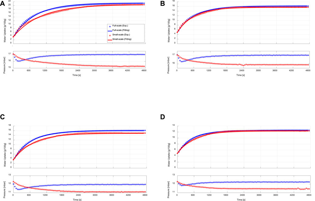
FIGURE 5. Adsorption kinetic (upper) and vapour pressure (lower) curves of the APHE (full-scale measurements) and its representative adsorbent sample (small-scale measurements) at evaporator, condenser/adsorption-end and desorption temperatures of (A) 15/30/90°C, (B) 15/35/90°C, (C) 10/30/90°C, (D) 10/35/90°C.
The exponential curve fittings are depicted also in Figure 5. As shown in the figure, all adsorption kinetic curves of the APHE and its representative adsorbent sample follow the exponential behaviour. Comparison between the adsorption kinetics of both the APHE and its representative adsorbent sample at every set of operating conditions could be made throughout the values of the time constants (
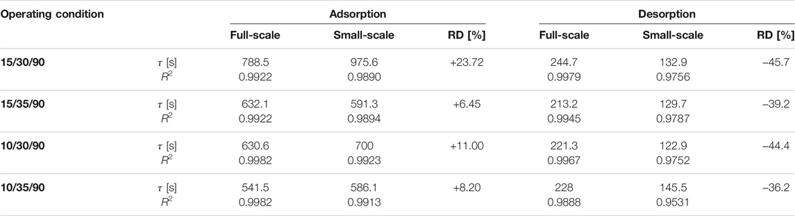
TABLE 2. Time constant of the exponential fitting (
The difference in the adsorption kinetics between the APHE and its representative adsorbent sample can be attributed to the difference in the pressure courses of variation between the water vapour surrounding the APHE and that surrounding the small adsorbent sample in the measuring cell of the V-LTJ kinetic setup, which have been recorded during the experimental processes and depicted also in Figures 5A–D (lower curves). Since the mass of water vapour filling the internal volume of the constant-volume kinetic setup (i.e., the internal volume of the vapour vessel, the measuring cell, and the connection between them) continuously decreases during the adsorption process, the pressure of the water vapour surrounding the investigated sample in the measuring cell decreases with the time of adsorption. The maximum pressure drop is reached at the end of the adsorption process and it is limited here to 2 mbar, as explained in Section 3.
In the adsorption kinetic measurements of the APHE, the time course of pressure variation of the water vapour surrounding the APHE and filling its chamber in the experimental setup is quite similar to that takes place in adsorber chambers of a real adsorption chiller or a heat pump. In other words, the pressure of the vapour surrounding the adsorber drops sharply during the first few seconds and then starts to be recovered and approaches its initial level at the end of the process upon reaching the corresponding equilibrium state. Such behavior has been faced in our lab-scale setup as well as in real adsorption heat pumps and chillers (Sztekler, 2021).
The difference in the adsorption kinetics between the adsorber and the small-scale adsorbent sample is quite small at the condenser temperature of 35°C. This can be attributed to the lower differential water uptake obtained in case of conducting adsorption processes with higher condenser (adsorption-end) temperature, leading to lower drop in the pressure of the vapour surrounding the small-scale adsorbent sample in the measuring cell and accordingly, lower difference in the pressure course between the water vapour surrounding the APHE and that surrounding the small adsorbent sample in measuring cell of the V-LTJ kinetic setup. Indeed, the final differential water uptake of the APHE at 10/30/90°C (12.37 g/100 g) and 15/35/90°C (11.33 g/100 g) is similar, see Figures 5B,C and the pressure drop of the vapour surrounding the small adsorbent sample in the measuring cell at both sets of operating conditions is almost equal (∼1.1 mbar). Indeed, the absolute pressure drop of 1.1 mbar represents 5.85% of the saturation pressure at the evaporator temperature of 15°C (Figure 5B) and 8.94% at the evaporator temperature of 10°C (Figure 5C), which explains the observed slower adsorption kinetics of the small-scale sample at 10°C.
Figure 6 depicts the desorption kinetic data obtained from the experimental investigation of the APHE and its representative adsorbent sample upon performing LTJ desorption processes at different sets of operating conditions. Indeed, the desorption kinetics of the APHE and the small-scale adsorbent sample are remarkably faster if compared with the adsorption kineties. As depicted in Table 2, the APHE demonstrates a faster desorption kinetics by an average factor of 2.85 relative to the adsorption kinetic. In addition, it is obvious that, the desorption kinetics of the small-scale representative sample are higher than those obtained from the full-scale APHE. The relative deviation in the desorption kinetic’s characteristic times between full-scale and small-scale measurements is clearly higher than the RD of the adsorption characteristic times. Strictly speaking the RD amounts to -36.2% in favor of the small-scale sample at the boundary condition 10/35/90°C, which increases to -45.7% at 15/30/90°C.
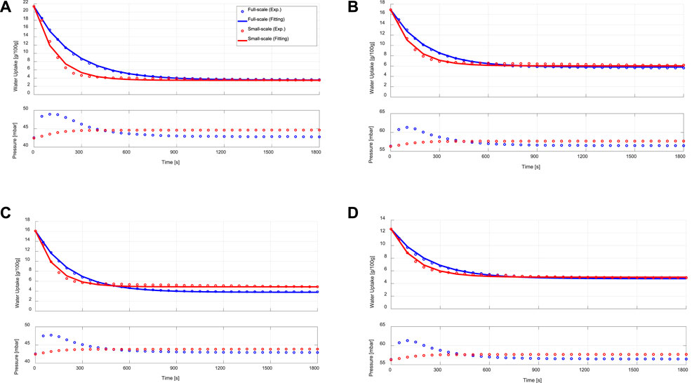
FIGURE 6. Desorption kinetic (upper) and vapour pressure (lower) curves of the APHE (full-scale measurements) and its representative adsorbent sample (small-scale measurements) at evaporator, condenser/adsorption-end and desorption temperatures of (A) 15/30/90°C, (B) 15/35/90°C, (C) 10/30/90°C, (D) 10/35/90°C.
The relatively large difference in the desorption kinetics between the APHE and the small-scale adsorbent sample can be attributed to the large difference in the pressure course of variation between the water vapour surrounding the APHE in its test setup and that surrounding the small adsorbent sample in the measuring cell of the V-LTJ kinetic setup, which are illustrated in the bottom diagrams of Figures 6A–D. For instance, at 15/30/90°C, the pressure of the water vapour surrounding the APHE in its test setup reaches to maximum value of 48.5 mbar in the first 110 s from the beginning of the desorption process and then starts to fall. After around 450 s, the pressure becomes equal to the pressure inside the small-scale V-LTJ apparatus. Recalling that the overall time needed for reaching equilibrium under this boundary condition, this means that the pressure of the full-scale apparatus was above that of the small-scale one over 50% of the process time, which explains why the desorption kinetics of the full-scale APHE are slower than those of the small-scale measurements. This is also the case in the other three boundary conditions. As shown in Figures 5A–D (lower diagrams) and Figures 6A–D (lower diagrams), the maximum vapour pressure drop in all conducted adsorption processes on the APHE does not exceed 1 mbar, whereas the maximum vapour pressure jump in the desorption processes exceeds 6 mbar, which explains the deviation in the desorption kinetics, which can’t be considered any more quasi-isobaric.
Indeed, the less efficient condenser performance does negatively influence the desorber kinetics in all full-scale measurements. Nevertheless, the deviation between the desorption small-scale and full-scale results is quite acceptable, as the adsorption time is always longer than the desorption time (in the recent APHE an average factor of 2.85 exists between the adsorption and desorption characteristic times), which means it plays the dominant role in estimating the cycle time of a real adsorption appliance. Considering the obtained very good matching between the adsorber kinetics of better than 24% (in average 12.37%), the introduced methodology to design small-scale samples (Mikhaeil et al., 2020) is quite promising for reducing the time and cost of developing efficient adsorber heat exchangers.
Instantaneous Evaporator and Condenser Powers
As the pressure difference between the water vapour surrounding the APHE in its experimental setup and that surrounding the adsorbent sample in the measuring cell is the cause of the difference in the adsorption and desorption kinetics as well as the final differential water uptake, comparing the APHE with its representative adsorbent sample only from the perspective of the temporal change of the water loading could be misleading. In other words, the success of predicting the performance of a real adsorber heat exchanger using small-scale representative adsorbent sample has to be judged from the perspective of the adsorption system output, such as the evaporator and condenser output powers. Accordingly, comparisons between the instantaneous and moving average specific powers obtained from the evaporator/condenser unit of the full-scale setup and the evaporation and condensation powers estimated from the adsorption and desorption kinetic results of the small-scale adsorbent sample may be more suitable indicators for the ability of a representative small-scale adsorbent sample in predicting the performance of a real adsorber heat exchanger.
Figures 7, 8 present comparisons between the instantaneous specific evaporation and condensation powers obtained from the evaporator/condenser unit of the APHE’s test setup and the instantaneous specific evaporation and condensation power estimated from the kinetic results of the small-scale adsorbent sample tested in the V-LTJ kinetic setup, respectively. The estimated instantaneous specific evaporator and condenser power based on the measured kinetic data of the small adsorbent sample have been estimated according to Eqs. 9, 10, respectively.
Where,
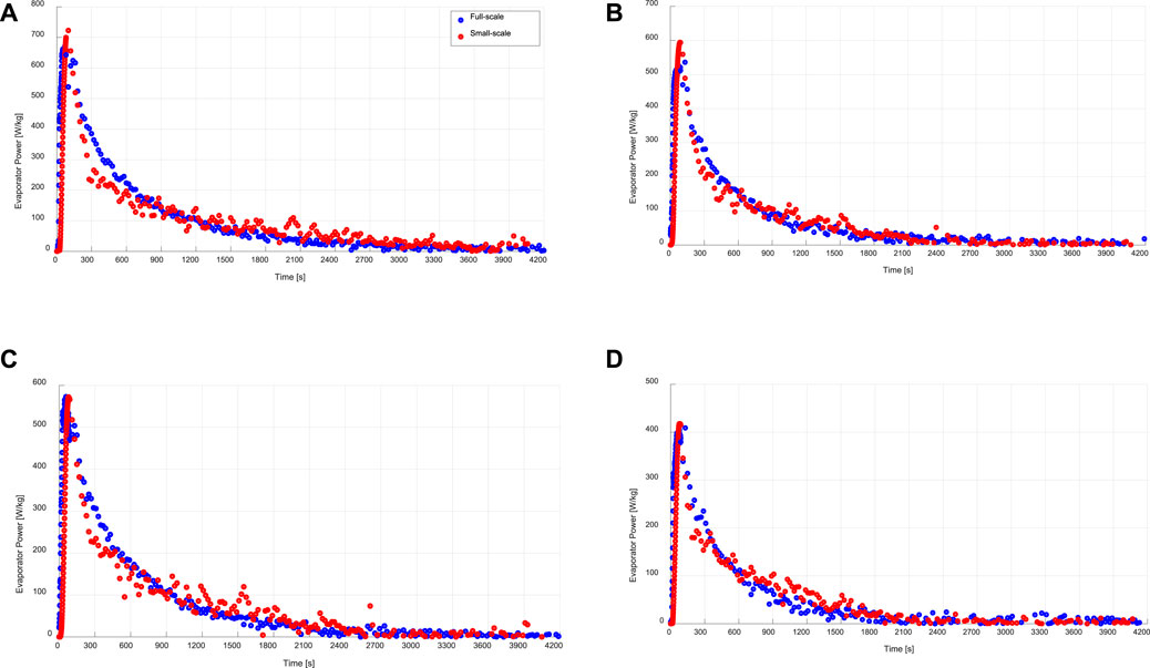
FIGURE 7. Instantaneous specific evaporation power of the evaporator/condenser unit (full-scale) and that estimated from the kinetic results of the adsorbent sample (small-scale), at a) 15/30/90°C, b) 15/35/90°C, c) 10/30/90°C, d)10/35/90°C.
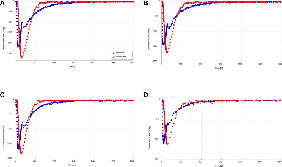
FIGURE 8. Instantaneous specific condensation power of the evaporator/condenser unit (full-scale) and that estimated from the kinetic results of the adsorbent sample (small-scale), at (A) 15/30/90°C, (B) 15/35/90°C, (C) 10/30/90°C, (C) 10/35/90°C.
As shown in Figure 7, at all applied operating conditions, there is a good agreement between the directly obtained evaporation power from the evaporator/condenser unit of the experimental setup built to investigate the APHE and the evaporation power estimated from the adsorption kinetics data of the small-scale adsorbent sample according to Eq. 9.
On the other hand, the condensation power estimated from the desorption kinetic results of the small-scale adsorbent sample at all applied operating conditions do not match very well with the power obtained from the evaporator/condenser unit obtained during the desorption-condensation processes on the investigated APHE (see Figure 8). This can be explained by the large difference in the temporal pressure courses of the water vapour surrounding the APHE and that surrounding the small adsorbent sample in their test setups during all conducted desorption processes. Nevertheless, it is obvious that the condensation energy is quite equal in both test methodologies. In addition, the maximum deviation in the maximum obtainable condenser power is less than 500 W. The plateau observable in the full-scale condenser power measurements has to do with the inlet temperature control of the desorber and condenser HTF loops.
Time-Averaged Evaporator and Condenser Powers
The time-averaged instantaneous specific evaporator and condenser power, which can be alternatively described as the moving average specific evaporator and condenser power is another useful indicator for evaluating the kinetic data of the small-scale measurements. Eq. 11 describes the mathematical formula for estimating the evaporator specific power out of the measured data of the small-scale sample. In other words, such a moving average specific evaporator power at a certain duration point (t) is the average evaporator power achievable, if the time assigned to the adsorption-evaporation process equals that duration (t). The obtained moving average evaporator powers for both full- and small-scale measurements are illustrated in Figure 9 under the four tested operating conditions.
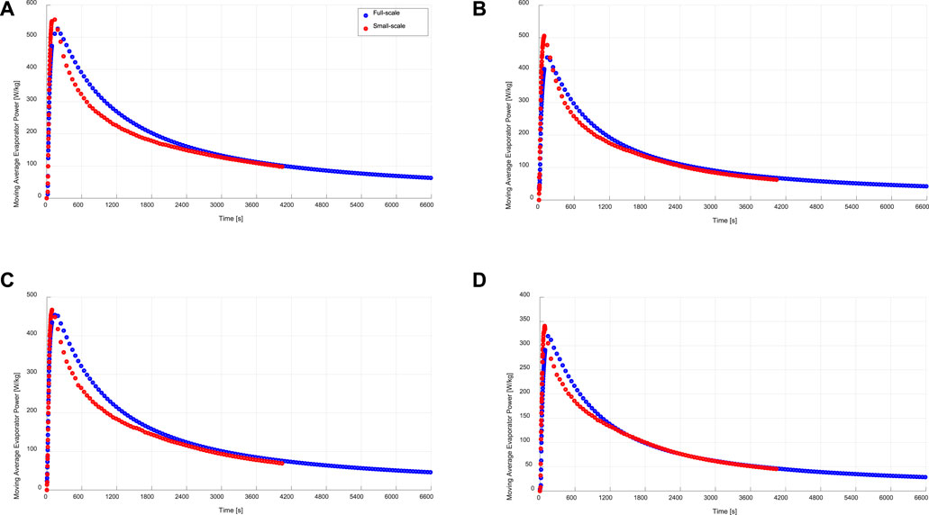
FIGURE 9. Specific moving average evaporation power of the evaporator/condenser unit (full-scale) and that estimated from the kinetic results of the adsorbent sample (small-scale), at (A) 15/30/90°C, (B) 15/35/90°C, (C) 10/30/90°C, (D) 10/35/90°C.
At the beginning of each tested processes, the driving force for adsorption is at its maximum value. Accordingly, the adsorption kinetics are the fastest and
Equation 12 describes the mathematical formulae for estimating the moving average specific condenser power out of the measured desorption kinetic data of the small-scale sample.
Figure 10 illustrates the obtained moving average specific condenser powers of both full- and small-scale measurements under the four sets of operating conditions. As depicted in Figure 10, the condensation powers estimated from the small-scale measurements are higher than those obtained from the full-scale measurements. The average relative deviation (ARD) in the moving specific average power is estimated according to Eq. (13).
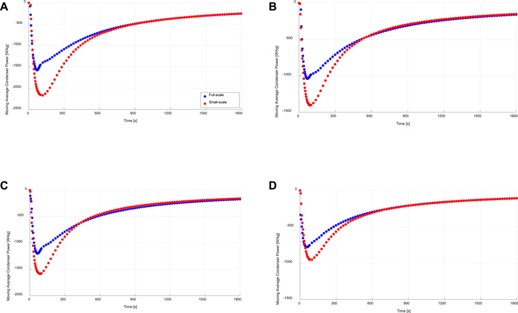
FIGURE 10. Specific moving average condensation power of the evaporator/condenser unit (full-scale) and that estimated from the kinetic results of the adsorbent sample (small-scale), at (A) 15/30/90°C, (B) 15/35/90°C, (C) 10/30/90°C, (D) 10/35/90°C.
Table 3 presents the estimated ARD for both moving average evaporator and condenser powers based on Eq. 13.
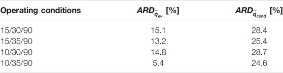
TABLE 3. Average relative deviation (
With a maximum ARD of 15.1% in the moving average evaporator power, it is evident again, that a very good matching between full- and small-scale measurements is reached. Contrary to that, the ARD in the moving average specific condenser power between the full- and small-scale measurements (
The obtained clear agreements between the adsorption water uptake data (Figure 5), instantaneous specific evaporator power (Figure 7) and the moving average specific evaporator power (Figure 9) between the APHE and its small-scale representative sample at all tested operating conditions implies the strength of the introduced methodology in (Mikhaeil et al., 2020), which has been verified in this work, to utilize the V-LTJ kinetic setup to precisely predict the performance of real adsorber heat exchangers before building them. Of course, special attention must be paid for analyzing the heat and mass transfer characteristics of the adsorbent domain of the adsorber heat exchanger before deciding on the dimensions of its representative test frame as described in (Mikhaeil et al., 2020) and applied in this work. Accordingly, design optimizations can be easily carried out based on the small-scale measurements before stepping to the fabrication and validation development phases, which shall save enormous development time and cost.
Conclusion
This study addresses the degree of matching between the adsorption and desorption kinetic measurements between a commercial, open-structured asymmetric plate heat exchanger adapted to act as an adsorber/desorber and a small-scale adsorbent sample prepared dedicatedly to be representative for the adsorbent domain inside the investigated adsorber/desorber plate heat exchanger (APHE) from the perspective of the heat and mass transfer characteristic lengths. To this aim, a special test setup has been established to investigate the adsorption and desorption kinetics of the full-scale APHE. A slight modification in the thermal response (LTJ) methodology (Tokarev, 2017) has been introduced. The adsorption and desorption kinetic investigation of the small-scale representative adsorbent sample has been conducted using a Volumetric Large Temperature Jump (V-LTJ) kinetic setup (Aristov et al., 2008). In addition, the kinetic data of the small-scale adsorbent sample have been utilized for estimating the expected instantaneous and moving average powers of the evaporator/condenser heat exchanger. The obtained small-scale and full-scale results have been compared and the main outcomes are summarized as follows:
1) All kinetic results of the small-scale adsorbent sample and the APHE have been fitted to an exponential form with coefficient of determination (R2) values better than 0.9531.
2) A very good matching between the small-scale and full-scale adsorption kinetic measurements has been obtained, with average relative deviation (RD) in the characteristic time constant of the exponential form (
3) The APHE demonstrated faster desorption kinetics than its adsorption kinetics by an average factor of 2.85. This is in phase with previous measurements and puts in evidence that the duration of the adsorption phase dominates the cycle time of the related adsorption appliance.
4) The RD in the desorption kinetics’ characteristic time (
5) The relatively large difference in the desorption kinetics between the APHE and the small-scale adsorbent sample was attributed to the large difference in the pressure course of variation between the water vapour surrounding the APHE in its test setup and that surrounding the small adsorbent sample in the measuring cell of the V-LTJ kinetic setup, implying a weak condenser performance of the test setup leading to higher water vapour pressures and, correspondingly, slower desorption kinetics.
6) The instantaneous and moving average specific evaporator power estimated from the adsorption kinetics data of the small-scale adsorbent sample matched very well with the ones obtained directly from the evaporator/condenser unit, against which the APHE has been tested, with an average relative deviation (ARD) between 5.4 and 15.1% for the moving average power.
7) The condenser moving average power estimated from small-scale measurements were higher than those obtained from the full-scale measurements, with an ARD between 24.6 and 28.7%, which is attributed to the weak condenser performance of the full-scale test unit.
Despite the relatively higher deviations of the desorption kinetic data, excellent agreements have been obtained for the adsorption kinetics regarding the temporal water uptake, instantaneous specific evaporator power and the moving average specific evaporator power between the APHE and its small-scale representative sample at all tested operating conditions. This puts in evidence the strength of the introduced methodology to mimic the heat and mass transfer characteristics of the adsorbent domain of a plate-type adsorber heat exchanger by dedicatedly design a test frame for a small-scale adsorbent sample, to be investigated with e.g. the V-LTJ kinetic setup to precisely predict the performance of the real adsorber heat exchangers before building it. Accordingly, design optimizations also concerning the influence of the adsorbent type and grain-size can be easily investigated on the small-scale level before realizing the full-scale heat exchanger, which shall save enormous development time and cost.
Data Availability Statement
The original contributions presented in the study are included in the article, further inquiries can be directed to the corresponding author.
Author Contributions
MM: Conceptualization, Methodology, Investigation, Formal analysis, Writing- original draft. MG: Supervision, Writing- Reviewing and Editing. BD: Funding acquisition, Project administration, Supervision, Conceptualization, Methodology, Formal analysis, Writing-Reviewing and Editing.
Funding
This project has received funding from the European Union’s Horizon 2020 research and innovation program under grant agreement No. 764025 (SWS-HEATING), which is gratefully acknowledged by the authors.
Conflict of Interest
The authors declare that the research was conducted in the absence of any commercial or financial relationships that could be construed as a potential conflict of interest.
Publisher’s Note
All claims expressed in this article are solely those of the authors and do not necessarily represent those of their affiliated organizations, or those of the publisher, the editors and the reviewers. Any product that may be evaluated in this article, or claim that may be made by its manufacturer, is not guaranteed or endorsed by the publisher.
Acknowledgments
The authors would like to thank the BayWISS Joint Academic Partnership “Energy” for their appreciated support.
Supplementary Material
The Supplementary Material for this article can be found online at: https://www.frontiersin.org/articles/10.3389/fenrg.2022.818486/full#supplementary-material
Footnotes
1https://www.alfalaval.com/globalassets/documents/products/heat-transfer/plate-heat-exchangers/gas-to-liquid-plate-heat-exchangers/glx/glx30_product-leaflet_en.pdf.
References
Aristov, Y. I. (2020). Dynamics of Adsorptive Heat Conversion Systems: Review of Basics and Recent Advances. Energy. 205, 101687. doi:10.1016/j.energy.2020.117998
Aristov, Y. I., Dawoud, B., Glaznev, I. S., and Elyas, A. (2008). A New Methodology of Studying the Dynamics of Water Sorption/desorption under Real Operating Conditions of Adsorption Heat Pumps: Experiment. Int. J. Heat Mass Transfer. 51 (19–20), 4966–4972. doi:10.1016/j.ijheatmasstransfer.2007.10.042
Aristov, Y. I., Glaznev, I. S., and Girnik, I. S. (2012). Optimization of Adsorption Dynamics in Adsorptive Chillers: Loose Grains Configuration. Energy. 46 (1), 484–492. doi:10.1016/j.energy.2012.08.001
Bau, U., Hoseinpoori, P., Graf, S., Schreiber, H., Lanzerath, F., Kirches, C., et al. (2017). Dynamic Optimisation of Adsorber-Bed Designs Ensuring Optimal Control. Appl. Therm. Eng. 125, 1565–1576. doi:10.1016/j.applthermaleng.2017.07.073
Bonaccorsi, L., Calabrese, L., Freni, A., Proverbio, E., and Restuccia, G. (2013). Zeolites Direct Synthesis on Heat Exchangers for Adsorption Heat Pumps. Appl. Therm. Eng. 50 (2), 1590–1595. doi:10.1016/j.applthermaleng.2011.10.028
Bonaccorsi, L., and Proverbio, E. (2004). Synthesis of Thick Zeolite 4A Coatings on Stainless Steel. Microporous Mesoporous Mater. 74 (1–3), 221–229. doi:10.1016/j.micromeso.2004.06.024
Çaǧlar, A. (2016). The Effect of Fin Design Parameters on the Heat Transfer Enhancement in the Adsorbent Bed of a thermal Wave Cycle. Appl. Therm. Eng. 104, 386–393. doi:10.1016/j.applthermaleng.2016.05.092
Calabrese, L., Bonaccorsi, L., and Proverbio, E. (2012). Corrosion protection of Aluminum 6061 in NaCl Solution by Silane-Zeolite Composite Coatings. J. Coat. Technol. Res. 9 (5), 597–607. doi:10.1007/s11998-011-9391-5
Canivet, J., Fateeva, A., Guo, Y., Coasne, B., and Farrusseng, D. (2014). Water Adsorption in MOFs: Fundamentals and Applications. Chem. Soc. Rev. 43, 5594–5617. doi:10.1039/c4cs00078a
Caprì, A. (2020). Recent Developments in Coating Technologies for Adsorption Heat Pumps: A Review. Coatings. 10 (9), 855. doi:10.3390/coatings10090855
Chakraborty, A., Saha, B. B., and Aristov, Y. I. (2014). Dynamic Behaviors of Adsorption Chiller: Effects of the Silica Gel Grain Size and Layers. Energy. 78, 304–312. doi:10.1016/j.energy.2014.10.015
Dawoud, B. (2018). Heat Exchanger, European Patent Application, EP 3 382 313 A1 (Application No. 17163555.0). Available at: https://worldwide.espacenet.com/patent/search/family/058454953/publication/EP3382313A1?q=17163555.0.
Dawoud, B. (2007). On the Effect of Grain Size on the Kinetics of Water Vapor Adsorption and Desorption Into/from Loose Pellets of FAM-Z02 under a Typical Operating Condition of Adsorption Heat Pumps. J. Chem. Eng. Jpn. 40 (13), 1298–1306. doi:10.1252/jcej.07WE163
Dawoud, B. (2013). Water Vapor Adsorption Kinetics on Small and Full Scale Zeolite Coated Adsorbers; A Comparison. Appl. Therm. Eng. 50 (2), 1645–1651. doi:10.1016/j.applthermaleng.2011.07.013
Frazzica, A., and Freni, A. (2017). Adsorbent Working Pairs for Solar thermal Energy Storage in Buildings. Renew. Energ. 110, 87–94. doi:10.1016/j.renene.2016.09.047
Freni, A., Bonaccorsi, L., Calabrese, L., Caprì, A., Frazzica, A., and Sapienza, A. (2015a). SAPO-34 Coated Adsorbent Heat Exchanger for Adsorption Chillers. Appl. Therm. Eng. 82, 1–7. doi:10.1016/j.applthermaleng.2015.02.052
Freni, A., Dawoud, B., Bonaccorsi, L., Chmielewski, S., Frazzica, A., Calabrese, L., et al. (2015b). springer Briefs in Applied Sciences and Technology Characterization of Zeolite-Based Coatings for Adsorption Heat Pumps. Available at: http://www.springer.com/series/8884.
Freni, A., Russo, F., Vasta, S., Tokarev, M., Aristov, Y. I., and Restuccia, G. (2007). An Advanced Solid Sorption Chiller Using SWS-1L. Appl. Therm. Eng. 27 (13), 2200–2204. doi:10.1016/j.applthermaleng.2005.07.023
Furukawa, H., Gándara, F., Zhang, Y.-B., Jiang, J., Queen, W. L., Hudson, M. R., et al. (2014). Water Adsorption in Porous Metal-Organic Frameworks and Related Materials. J. Am. Chem. Soc. 136 (11), 4369–4381. doi:10.1021/ja500330a
Golparvar, B., Niazmand, H., Sharafian, A., and Ahmadian Hosseini, A. (2018). Optimum Fin Spacing of Finned Tube Adsorber Bed Heat Exchangers in an Exhaust Gas-Driven Adsorption Cooling System. Appl. Energ. 232, 504–516. doi:10.1016/j.apenergy.2018.10.002
Gong, L. X., Wang, R. Z., Xia, Z. Z., and Chen, C. J. (2011). Design and Performance Prediction of a New Generation Adsorption Chiller Using Composite Adsorbent. Energ. Convers. Management. 52 (6), 2345–2350. doi:10.1016/j.enconman.2010.12.036
Gordeeva, L., Frazzica, A., Sapienza, A., Aristov, Y., and Freni, A. (2014). Adsorption Cooling Utilizing the "LiBr/silica - Ethanol" Working Pair: Dynamic Optimization of the Adsorber/heat Exchanger Unit. Energy. 75, 390–399. doi:10.1016/j.energy.2014.07.088
Graf, S., Redder, F., Bau, U., de Lange, M., Kapteijn, F., and Bardow, A. (2020). Toward Optimal Metal–Organic Frameworks for Adsorption Chillers: Insights from the Scale-Up of MIL-101(Cr) and NH 2 -MIL-125. Energ. Technology. 8 (1), 1900617. doi:10.1002/ente.201900617
Hajji, A., and Khalloufi, S. (1996). Improving the Performance of Adsorption Heat Exchangers Using a Finned Structure. Int. J. Heat Mass Transfer. 39, 1677. doi:10.1016/0017-9310(95)00254-5)
Hong, S. W., Ahn, S. H., Kwon, O. K., and Chung, J. D. (2015). Optimization of a Fin-Tube Type Adsorption Chiller by Design of experiment. Int. J. Refrigeration. 49, 49–56. doi:10.1016/j.ijrefrig.2014.09.022
Ilis, G., Demir, H., Mobedi, M., and Baran Saha, B. (2019). A New Adsorbent Bed Design: Optimization of Geometric Parameters and Metal Additive for the Performance Improvement. Appl. Therm. Eng. 162, 114270. doi:10.1016/j.applthermaleng.2019.114270
Li, J., Kubota, M., Watanabe, F., Kobayashi, N., and Hasatani, M. (2004). Optimal Design of a Fin-type Silica Gel Tube Module in the Silica Gel/Water Adsorption Heat Pump. J. Chem. Eng. Jpn. 37 (4), 551–557. doi:10.1252/jcej.37.551
Mikhaeil, M., Gaderer, M., and Dawoud, B. (2020). On the Development of an Innovative Adsorber Plate Heat Exchanger for Adsorption Heat Transformation Processes; an Experimental and Numerical Study. Energy. 207, 118272. doi:10.1016/j.energy.2020.118272
Muttakin, M., Pal, A., Rupa, M. J., Ito, K., and Saha, B. B. (2021). A Critical Overview of Adsorption Kinetics for Cooling and Refrigeration Systems. Adv. Colloid Interf. Sci. 294, 102468. doi:10.1016/j.cis.2021.102468
Niazmand, H., and Dabzadeh, I. (2012). Numerical Simulation of Heat and Mass Transfer in Adsorbent Beds with Annular Fins. Int. J. Refrigeration. 35 (3), 581–593. doi:10.1016/j.ijrefrig.2011.05.013
Oh, S. J., Ng, K. C., Chun, W., and Chua, K. J. E. (2017). Evaluation of a Dehumidifier with Adsorbent Coated Heat Exchangers for Tropical Climate Operations. Energy 137, 441–448. doi:10.1016/j.energy.2017.02.169
Palomba, V., Dawoud, B., Sapienza, A., Vasta, S., and Frazzica, A. (2017). On the Impact of Different Management Strategies on the Performance of a Two-Bed Activated Carbon/Ethanol Refrigerator: An Experimental Study. Energ. Convers. Management. 142, 322–333. doi:10.1016/j.enconman.2017.03.055
Santamaria, S., Sapienza, A., Frazzica, A., Freni, A., Girnik, I. S., and Aristov, Y. I. (2014). Water Adsorption Dynamics on Representative Pieces of Real Adsorbers for Adsorptive Chillers. Appl. Energ. 134, 11–19. doi:10.1016/j.apenergy.2014.07.053
Sapienza, A., Frazzica, A., Freni, A., and Aristov, Y. (2016). Dramatic Effect of Residual Gas on Dynamics of Isobaric Adsorption Stage of an Adsorptive Chiller. Appl. Therm. Eng. 96, 385–390. doi:10.1016/j.applthermaleng.2015.09.031
Sztekler, K. (2021). Optimisation of Operation of Adsorption Chiller with Desalination Function. Energies. 14 (9), 2668. doi:10.3390/en14092668
Tatlıer, M. (1999). The Effects of thermal and Mass Diffusivities on the Performance of Adsorption Heat Pumps Employing Zeolite Synthesized on Metal Supports. Microporous Mesoporous Mater. 28 (1), 195–203. doi:10.1016/S1387-1811(98)00301-1
Tokarev, M. M., and Aristov, I. (2017). A New Version of the Large Temperature Jump Method: The thermal Response (T–LTJ). Energy. 140. doi:10.1016/j.energy.2017.08.093
Keywords: adsorber, adsorbent sample, desorber, kinetics, plate heat exchanger
Citation: Mikhaeil M, Gaderer M and Dawoud B (2022) Experimental Investigation of the Adsorption and Desorption Kinetics on an Open-Structured Asymmetric Plate Heat Exchanger; Matching Between Small-Scale and Full-Scale Results. Front. Energy Res. 10:818486. doi: 10.3389/fenrg.2022.818486
Received: 19 November 2021; Accepted: 14 February 2022;
Published: 07 March 2022.
Edited by:
Kim Choon Ng, King Abdullah University of Science and Technology, Saudi ArabiaReviewed by:
Alessio Sapienza, Istituto Di Tecnologie Avanzate per L’Energia “Nicola Giordano” (ITAE), ItalyBidyut Baran Saha, Kyushu University, Japan
Copyright © 2022 Mikhaeil, Gaderer and Dawoud. This is an open-access article distributed under the terms of the Creative Commons Attribution License (CC BY). The use, distribution or reproduction in other forums is permitted, provided the original author(s) and the copyright owner(s) are credited and that the original publication in this journal is cited, in accordance with accepted academic practice. No use, distribution or reproduction is permitted which does not comply with these terms.
*Correspondence: Belal Dawoud, YmVsYWwuZGF3b3VkQG90aC1yZWdlbnNidXJnLmRl