 Peifeng Lin*
 Tao Yang
95% of researchers rate our articles as excellent or good
Learn more about the work of our research integrity team to safeguard the quality of each article we publish.
Find out more
ORIGINAL RESEARCH article
Front. Energy Res. , 26 January 2022
Sec. Process and Energy Systems Engineering
Volume 10 - 2022 | https://doi.org/10.3389/fenrg.2022.818244
This article is part of the Research Topic Design, Simulation and Optimization of Hydraulic Machinery View all 25 articles
The efficiency of the impeller machinery can be improved by the inlet guide vanes, but the relationship between the external characteristics of the centrifugal pump and the internal flow state needs further study. In this paper, the flow characteristics of the centrifugal pump with different offset angles of inlet guide vanes (IGVs) are simulated based on the SST k-ω turbulence model. The influence of the offset angle of the IGV on the internal flow and energy dissipation of the centrifugal pump is analyzed by using the entropy generation theory and Q-criterion. The research results show that the increase of the offset angle is beneficial to reducing the intensity of vortex in the volute and impeller, while the energy loss is reduced by 21.12 and 17.82% at 0.6Qd and 0.8Qd, respectively. However, the excessive offset angle of the IGV tends to cause greater energy loss in the inlet pipe, thus reducing the head and efficiency of the centrifugal pump. In terms of external characteristics, the pump with 25° IGVs has the best head and efficiency improvement. Under three small operating points, the pump with 25° IGVs increased the head by 2.11, 0.95, and 0.73% and the efficiency by 2.51, 1.67, and 1.25%, respectively, compared with the pump with 0° IGVs. The research in this paper contributes to the performance improvement of centrifugal pumps operating at low flow conditions.
Pumps, a machine for converting energy, are widely used in social production practices (Martinich, 1990; Aaronson et al., 2012). The internal flow of a centrifugal pump is turbulent, which is very different from the laminar flow in some straight channels. Therefore, its internal flow is more complicated (Hu et al., 2020; Hu et al., 2021). Due to the complexity of the flow in the pump, it may have an unstable working operation. For improving the operational performance of centrifugal pumps, researchers have done a lot of research studies in improving the energy conversion efficiency of pumps (Xiong, 1996; Dou et al., 2014; Wang et al., 2018). A common study of pumps includes regulating the intrinsic parameters such as the size structure of the pump and the shape and number of blades. With the continuous development of research, researchers are increasingly interested in the study of adding guide vanes inside various fluid machinery. And some experiments and numerical simulations also prove that IGVs can improve the operating performance of fluid machinery (Dou, 2006; Liu et al., 2011; Shi et al., 2012; Kim et al., 2013).
As early as the 1950s, the method of adjusting working conditions of the impeller machinery such as centrifugal compressors, fans, and turbines by adding IGVs had been widely used. Coppinger and Swain (2000) investigated the effect of guide vanes with an angle ranging from −20° to +80° on industrial centrifugal compressors through experiments and simulations. They found that an excessively large setting angle led to a larger pressure loss, which resulted in a reduction of the overall system efficiency. A suitable angle of guide vanes had a significant effect on extending the stable operating range of the compressor. The performance of centrifugal compressors with IGVs was also studied by Xiao et al. (2006). He demonstrated that the performance curve of centrifugal pumps moved toward the low flow region when guide vanes were positively offset. The opposite result was obtained when they were negatively offset. In the low flow region, the optimal efficiency operating point of the centrifugal pump decreased faster. Fukutomi and Nakamura (2005) investigated the effect of angle and length of IGVs on the performance of cross-flow turbines. By installing guide vanes in the inlet region, the cross-flow turbines had higher pressure and higher efficiency compared to the case without guide vanes. In the high flow condition, the turbines obtained higher pressure and efficiency. But in the low flow condition, the presence of the guide vanes had an inhibiting effect on the circulating flow in the rotor inlet. To address the flow inhomogeneities in centrifugal turbines, Junaidi et al. (2015) installed guide vanes at the impeller inlet of the turbine to eliminate the vortex flow due to internal deformation. Comparing the internal static pressure and axial power of centrifugal fans with and without IGVs, they noticed that the stable operating range of centrifugal fans was extended and the power consumption was reduced under off-design conditions. Based on the above research, the purpose of this article is to understand the effect of the law of inlet guide vanes on the flow field and external characteristics of the centrifugal pump.
In this paper, the flow characteristics of the centrifugal pump with IGVs are simulated. The influence of the law of inlet guide vanes on the pressure, velocity, and other physical quantities of the internal flow field of the centrifugal pump is studied by a steady calculation method. Combined with the energy dissipation in the impeller, the influence of guide vanes with an angle ranging from 0° to 35° on the performance of centrifugal pumps is revealed. The reasons why the offset angle of guide vanes should not be too large are specifically analyzed, and the microscopic mechanism of external characteristics is elucidated. This study provides a certain reference for the selection of the pre-selection angle of the inlet guide vane of the centrifugal pump, and it is of great practical significance to guarantee the long-term and efficient operation of the centrifugal pump.
The centrifugal pump can be divided into four parts according to the overall flow (Li et al., 2018; Li et al., 2020): impeller flow channel, inlet flow channel, outlet flow channel, and volute flow channel. In consideration of reducing the disturbance and stabilizing the flow, a cylindrical extension of four times the diameter is added to the impeller inlet and volute outlet, respectively, in the computational domain model. Pro/Engineer software is used to model the full flow channel of the centrifugal pump, and the 3D model obtained is shown in Figure 1. The structural design parameters of the pump are shown in Table 1.
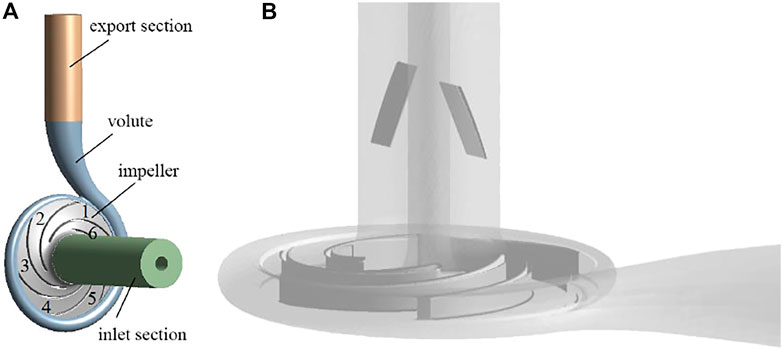
FIGURE 1. Three-dimensional model of the centrifugal pump: (A) geometric model; (B) overall perspective view of the centrifugal pump with IGVs.
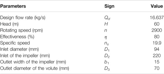
TABLE 1. Main design parameters of the centrifugal pump.
Two symmetrical inlet straight thick guide vanes were arranged in the inlet section of the centrifugal pump, and the schematic diagram of the guide vane is shown in Figure 2. The length of the vane a is 40 mm, the width b is 50 mm, the thickness c is 2 mm, the distance of the vane from the impeller inlet is 60 mm, and the offset angle between the vane and the axial direction is θ. The geometric shapes of IGVs at different offset angles are demonstrated in Figure 3.

FIGURE 2. Schematic diagram of inlet guide vanes: (A) side view; (B) radial view.
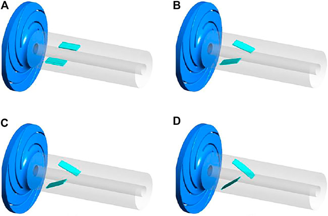
FIGURE 3. IGVs at different offset angles: (A) 0°; (B) 15°; (C) 25°; (D) 35°.
The multiple reference frame (MRF) method is used for data transfer between dynamic and static computational domains. The meshes are generated for impellers and IGVs with ANSYS ICEM, and the meshes of IGVs and impellers are exhibited in Figure 4. Local refinement is used to improve the simulation accuracy.
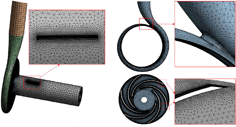
FIGURE 4. Mesh of IGVs, volute, and impeller.
The shear stress transport (SST) k-ω turbulence model was applied to solve the flow equations in this study. It has the capability to predict the flow within a side channel pump after evaluating the effects of different turbulence models. And the k-ω model can better simulate turbulent flow away from the wall and has a wider application for solving boundary layer problems under various pressure gradients (Wang, He, Shi et al., 2019; Li et al., 2019; Pei et al., 2019). The boundary condition at the pump inlet and outlet is set to the mass flow rate and pressure, respectively. And the no-slip condition is applied on pump walls, and the scalable wall function is used for near-wall regions. The control equations are as follows.
k equation:
ω equation:
The turbulent viscosity is calculated using
Here, β′, α, β, σk, and σω are empirical model parameters: β′ = 0.09, α = 5/9, β = 0.075, and σk = σω = 2.
The second law of thermodynamics states that the entropy of an isolated system does not decrease, also known as the principle of entropy increase. Fluid flow in centrifugal pump is complex and vortex currents are created. Fluid-fluid interactions and fluid-wall interactions result in fluid energy loss. The entropy generation rate (EGR) in turbulent flow consists of two terms: the first part caused by the dissipation in the averaged flow (direct or viscous dissipation) and the other part due to the dissipation in the fluctuating terms of the flow (turbulent dissipation). The unit volume entropy generation is defined as
where
where
Based on investigations by Kock and Herwig (2004), Herwig and Kock (2006), and Eliezer and Cohen (2001), the specific entropy generation rate due to the turbulent dissipation
Furthermore, Eq. 7 can be approximately given by the following expression:
where k and ω are the turbulence kinetic energy and characteristic frequency in the shear stress transport (SST) model, respectively. C is an empirical constant and equals 0.09 (Menter, 1994).
A reasonable selection of the number of meshes can both speed up the calculation and ensure the accuracy and reliability of the simulation results (Li et al., 2017; Wang, He, Cheng et al., 2019). Four groups of computational models with different grid numbers were used for numerical simulations, and their heads were obtained separately, as shown in Table 2. The result shows that all the deviations are within 0.5%. Taking the factors such as saving computing resources and computing time into account, the third grid was finally selected. The accuracy and reliability of the numerical method were verified as well by comparing the simulation pump head and efficiency with experiment results under different flow rates (Lin et al., 2020).

TABLE 2. Grid independence check for the simulation.
The results of the external characteristic curves of the pump with IGVs of different offset angles at small operating conditions are shown in Figure 5. From Figure 5, it can be seen that the head and efficiency of the pump with 15°, 25°, and 35° IGVs are higher than those of the pump with 0° IGVs at each small operating condition, and the pump with 25° IGVs has the greatest increase in head and efficiency. Comparing the differences of the head and efficiency of the pump with 0° IGVs and the pump with 25° IGVs under different flow conditions, the head increased by 2.11, 0.95, and 0.73% at the three small flow conditions of 0.4Qd, 0.6Qd, and 0.8Qd, respectively, and the efficiency increased by 2.51, 1.67, and 1.25%, respectively. In order to study the intrinsic microscopic mechanism of the above external results, the internal flow of the centrifugal pump was analyzed. Considering the actual operating environment of the centrifugal pump and the range of operating conditions studied in this paper, we selected the 0.6Qd operating point and the 0.8Qd operating point for the internal flow study.

FIGURE 5. External characteristics of centrifugal pumps: (A) flow-head; (B) flow-efficiency.
Figure 6 shows the streamlines of relative velocity at mid-section (the location of each flow path is shown in Figure 1A). When the centrifugal pump is operated under low flow conditions, different degrees of vortices appeared in both path 1 and path 6 near the tongue, and the vortices resulted in large vortex cores in the impeller path. Compared with the 0.8Qd operating point, the dynamic and static interference between the tongue and the impeller is more obvious at the 0.6Qd operating point, and the flow pattern in path 1 and path 6 is more turbulent. At the 0.6Qd operating point, the increase of the vane angle is beneficial to reducing the scale of vortices in the flow path. Besides, the area of the vortex core in flow path 1 is the smallest, and there is no large-area agglomeration. At the 0.8Qd operating point, there are almost no vortices in flow path 1 and the area of the low velocity region is minimal.
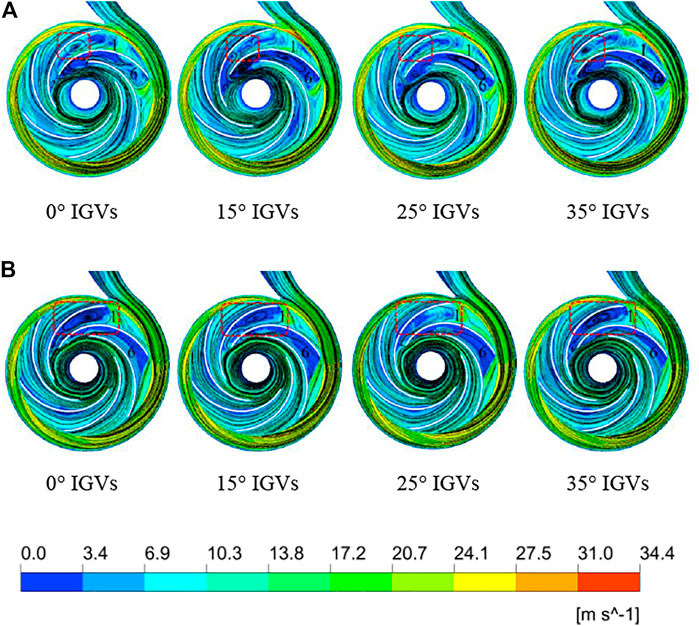
FIGURE 6. Streamlines of relative velocity at the cross-section: (A) 0.6Qd and (B) 0.8Qd.
The volute is divided into zones, as shown in Figure 7. The VI and VIII sections of the volute shown in Figure 7 are selected, and their flow is analyzed. The velocity contour and streamlines of the mid-sections under two operating conditions are shown in Figure 8. The offset angle of the guide vane has a certain influence on the size and position of the vortex in the volute section, and the pump with 25° IGVs is the most effective in reducing the size of the vortex. At 0.8Qd operating conditions, the 25° IGV pump has a more stable flow in Section VIII near the spacer tongue. The above results indicate that the increase of the angle has a certain effect on improving the flow pattern near the tongue. The 0.8Qd operating point is closer to the design point, and its scale of vortices is reduced compared with that of 0.6Qd.
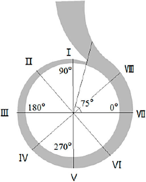
FIGURE 7. Circumferential angle and cross-section distribution of the volute.
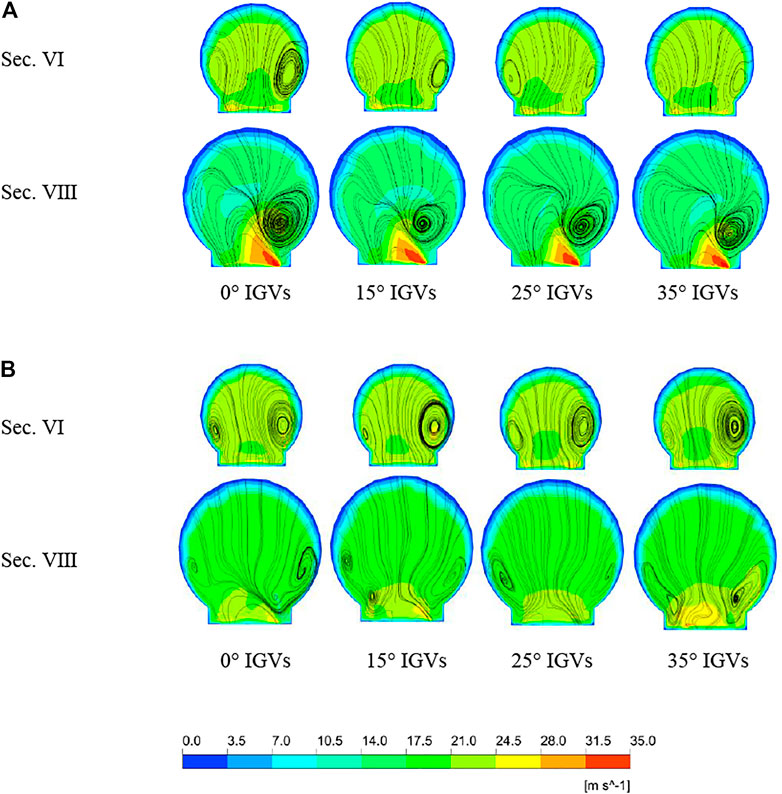
FIGURE 8. Velocity contours and streamlines of four pump sections under two operating points. (A) 0.6Qd and (B) 0.8Qd.
The relationship between the flow inside the centrifugal pump and the energy loss can be visualized in Figure 9. The vortex in the impeller is represented by the Q-criterion, and the actual value of the Q-criterion is 3.6 × 10⁵ s−2. At the 0.6Qd operating point, a larger range of high Q regions appears in flow path 1 of four pumps due to the stronger dynamic and static interference near the tongue. Since the flow of the pump with 25° IGVs is more stable, the area of vortex core in flow path 1 is the smallest. From Figure 9, it can be obtained that the increase in the vane’s angle is conducive to reducing the intensity of the vortex and the local entropy generation rate (EGR) in the flow path. At the operating point of 0.8Qd, the effect of increasing the offset angle on reducing the area of vortex core in the flow path is more obvious, indicating that 15°, 25°, and 35° offset angles can effectively suppress the flow turbulence.
FIGURE 9. Local EGRs and vortex cores of the centrifugal pump with vanes of different offset angles: (A) 0.6Qd and (B) 0.8Qd.
The local entropy generation rate for the pump with vanes of different angles at 0.6Qd and 0.8Qd operating points is illustrated in Figure 10. And the percentage reduction of energy loss in the cross-section for the four pumps is shown in Table 3 (percentage represents the relative ratio of energy loss to that of the pump with 0° IGVs). The energy loss in the section tends to decrease with the increase of the guide vane angle. Compared with that of the pump with 0° IGVs, the energy loss of the pump with 25° IGVs in the cross-section is reduced by 21.12 and 17.82% for the two operating conditions, respectively. The influence of the offset angle on the internal flow of the centrifugal pump is shown as follows: the 25° IGV has the best improvement impact on flow path 1 near the tongue, and the pump’s head and efficiency have improved the most. The larger vortex core area of flow path 1 in the pump with 0° IGVs indicates a much more complex vortex structure in flow path 1, which results in more energy dissipation during energy transport.
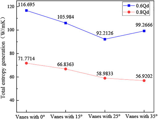
FIGURE 10. Entropy generation rate at 0.6Qd and 0.8Qd operating points.

TABLE 3. Relative percentage reduction of energy loss at 0.6Qd and 0.8Qd operating points.
From the above analysis results and combined with the efficiency and head curves, it can be seen that the increase of the vane angle can improve the flow pattern of fluid in the volute and impeller, increasing the head and efficiency of the centrifugal pump. In order to further reveal the reason why the offset angle of the IGV should not be too large, we subjected the inlet of the centrifugal pump with 25° and 35° IGVs to flow and loss analysis. The contour of the entropy generation rate is depicted in Figure 11 for five different cross-sections of the inlet, and the inlet vortex core of two pumps is characterized in Figure 12. The actual value of the Q-criterion is 9 × 10⁴ s−2. Compared with the 0.6Qd operating point, the 0.8Qd operating point which is closer to the design point has a lower entropy generation rate under the same condition. In both operating conditions, the loss of energy near the inlet increases with the increase of the offset angle.
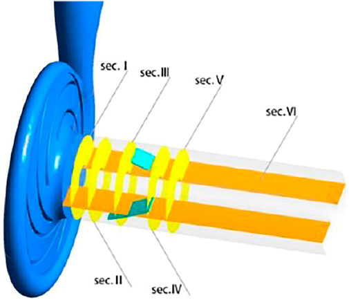
FIGURE 11. Cross-sections of the inlet pipe.
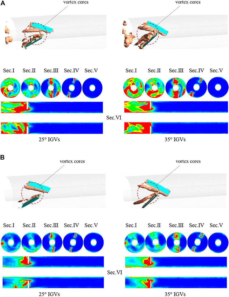
FIGURE 12. Contours of the entropy generation rate at different cross-sections and vortex cores of the inlet pipe: (A) 0.6Qd and (B) 0.8Qd.
The distribution of vortex core in the inlet pipe is more consistent with the variation of energy loss: the higher Q value of the region corresponds to the larger energy loss, which indicates that the energy loss near the vanes is mainly caused by vortices. It is obvious from Figure 12 that the core is mainly distributed in the suction side of the guide vane, which means that the fluid flowing around the guide vanes will produce vortex in the suction side of the guide vane. The above analysis can be summarized as follows: it can be concluded that, for the same operating point, the 35° IGV causes a larger vortex compared to the 25° IGV. Excessive offset angle of the IGV increases the flow turbulence near the inlet, intensifying the hydraulic losses and making the head and efficiency smaller.
Figure 13 shows the static pressure distribution at the cross-section in the centrifugal pump. The static pressure distribution pattern in the pump is basically the same in both operating points. As the flow rate increases, the pressure at the outlet of the volute gradually decreases, but the area of higher pressure remains in the volute. At the 0.8Qd operating point, the pressure at the volute outlet is the lowest. In the impeller flow path, the pressure value increases continuously from the impeller inlet to the outlet. But in the flow path near the tongue, the pressure value distribution is different from that in the other flow paths due to the influence of the tongue, and the pressure gradient is more uneven. At the impeller inlet, due to the energy loss, low-pressure areas appear in both operating conditions, and the low-pressure area is not uniformly distributed. In both operating points, the low-pressure area of the impeller inlet of pumps with 15°, 25°, and 35° IGVs is smaller than that of the pump with 0° IGVs, indicating that the increase in the offset angle of IGVs can reduce the energy loss at the impeller inlet. Of the four pumps studied, the pump with 25° IGVs has the best effect on the pump’s impeller inlet pressure improvement: the low-pressure area is smaller and the distribution of the low-pressure area is more uniform.

FIGURE 13. Contours of static pressure at the cross-section: (A) 0.6Qd and (B) 0.8Qd.
The pressure distribution at the interface between the volute and the impeller is shown in Figure 14, and the pressure is distributed periodically. In the vicinity of the tongue, the pressure fluctuation is more violent. As the flow rate decreases, the pressure fluctuation near the tongue becomes more and more violent. The pump with 0° IGVs has the lowest pressure at the impeller outlet near the tongue, while the pump with 25° IGVs has the most significant pressure boost. At the position away from the tongue, the pressure distribution at the intersection of the volute and impeller is basically the same for all four pumps, which indicates that the offset angle has no significant effect on the flow at locations away from the tongue.
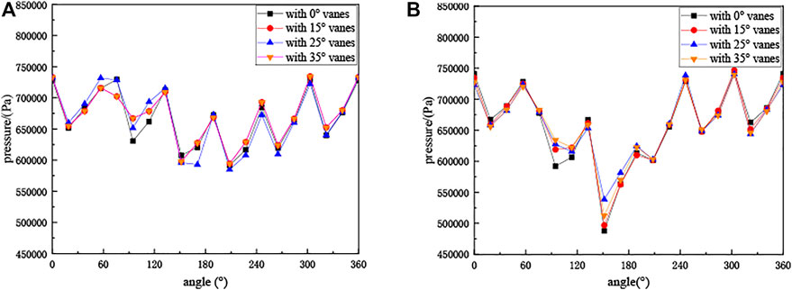
FIGURE 14. Pressure distribution at the intersection of the volute and impeller: (A) 0.6Qd and (B) 0.8Qd.
The flow characteristics of the centrifugal pump with IGVs of different offset angles were numerically simulated, and the effects of offset angle on the impeller flow, volute flow, and inlet flow were compared and analyzed. Some conclusions are as follows:
1) At 0.4Qd, 0.6Qd, and 0.8Qd operating points, the head and efficiency of pumps with 15°, 25°, and 35° IGVs are higher than those of the pump with 0° IGVs. Among the studied pumps, the head and efficiency of the pump with 25° IGVs have improved the most. The pump with 25° IGVs increased the head by 2.11, 0.95, and 0.73% and the efficiency by 2.51, 1.67, and 1.25%, respectively, compared with that with 0° IGVs.
2) The angle of the IGV has a more pronounced effect on the flow in the flow path near the tongue. The pump with 0° IGVs has a strong vortex in the impeller and a complex flow near the tongue, which always has the largest energy loss. On the contrary, when the IGV is installed at an angle of 25°, the impeller inlet low-pressure area is weakened and the turbulent kinetic energy near the tongue is smaller. It can better reduce the hydraulic loss caused by inlet shock, flow separation, and vortex, thus increasing the pump head and efficiency.
3) Fluid flow around the guide vane will produce vortex on the suction side of the vane, making the energy loss on the suction side greater than that on the pressure side. And the larger the angle of the guide vane, the greater the energy loss on the suction side of the vane. The energy loss of the inlet is the reason why the external characteristics of the centrifugal pump are not proportional to the angle of the IGV.
4) Setting a certain offset angle of the inlet guide vane can inhibit the backflow and separation flow of the impeller inlet and improve the internal flow state of the impeller. And it is beneficial to reducing the energy loss in the impeller so that the centrifugal pump exhibits a higher head and efficiency.
The original contributions presented in the study are included in the article/supplementary material, and further inquiries can be directed to the corresponding author.
PL and ZZ contributed with conceptualization and writing original draft preparation. TY and WX carried out the experiment validation. All authors have read and agreed to the published version of the manuscript.
This work was financially supported by the Key R&D Program of Zhejiang Province (Grant No. 2020C03081), the Joint Funds of the National Natural Science Foundation of China (Grant No. U2006221), the National Natural Science Foundation of China (Grant No. 51676173), and the Top-notch Talent Support Program of Zhejiang Province (Grant No. 2019R51002). The supports are gratefully acknowledged.
The authors declare that the research was conducted in the absence of any commercial or financial relationships that could be construed as a potential conflict of interest.
All claims expressed in this article are solely those of the authors and do not necessarily represent those of their affiliated organizations, or those of the publisher, the editors, and the reviewers. Any product that may be evaluated in this article, or claim that may be made by its manufacturer, is not guaranteed or endorsed by the publisher.
Aaronson, K. D., Slaughter, M. S., Miller, L. W., McGee, E. C., Cotts, W. G., Acker, M. A., et al. (2012). Use of an Intrapericardial, Continuous-Flow, Centrifugal Pump in Patients Awaiting Heart Transplantation. Circulation 125 (25), 3191–3200. doi:10.1161/CIRCULATIONAHA.111.058412
Coppinger, M., and Swain, E. (2000). Performance Prediction of an Industrial Centrifugal Compressor Inlet Guide Vane System. Proc. Inst. Mech. Eng. A: J. Power Energ. 214 (2), 153–164. doi:10.1243/0957650001538254
Dou, H.-S. (2006). Mechanism of Flow Instability and Transition to Turbulence. Int. J. Non-Linear Mech. 41 (4), 512–517. doi:10.1016/j.ijnonlinmec.2005.12.002
Dou, H., Jiang, W., Zhang, Y., Zhu, Z., Cui, B., and Li, Y. (2014). Flow Instability in Centrifugal Pump Based on Energy Gradient Theory. Trans. Chin. Soc. Agric. machinery 45 (12), 88–92. doi:10.6041/j.issn.1000-1298.2014.12.014
Eliezer, K., and Cohen, J. (2001). An Introduction to Turbulent Flow by Jean Mathieu and Julian Scott, Cambridge University Press, 2000, ISBN 0521570662. Int. J. Multiphase Flow 27 (9), 1655–1656. doi:10.1016/S0301-9322(01)00020-9
Fukutomi, J., and Nakamura, R. (2005). Performance and Internal Flow of Cross-Flow Fan with Inlet Guide Vane. JSME International Journal. Ser. B, Fluids Thermal Engineering 48 (4), 763–769. doi:10.1299/jsmeb.48.763
Herwig, H., and Kock, F. (2006). Direct and Indirect Methods of Calculating Entropy Generation Rates in Turbulent Convective Heat Transfer Problems. Heat Mass. Transfer 43 (3), 207–215. doi:10.1007/s00231-006-0086-x
Hu, X., Lin, J., Chen, D., and Ku, X. (2020). Stability Condition of Self-Organizing Staggered Particle Trains in Channel Flow. Microfluidics and Nanofluidics 24 (25), 1–12. doi:10.1007/s10404-020-2329-4
Hu, X., Lin, J., Guo, Y., and Ku, X. (2021). Motion and Equilibrium Position of Elliptical and Rectangular Particles in a Channel Flow of a Power-Law Fluid. Powder Technol. 377, 585–596. doi:10.1016/j.powtec.2020.09.028
Junaidi, M. A. R., Kumari, N. B. V. L., Samad, M. A., and Ahmed, G. M. S. (2015). CFD Simulation to Enhance the Efficiency of Centrifugal Pump by Application of Inner Guide Vanes. Mater. Today Proc. 2 (4-5), 2073–2082. doi:10.1016/j.matpr.2015.07.200
Kim, S., Heo, S., Cheong, C., and Kim, T.-H. (2013). Numerical and Experimental Investigation of the Bell-mouth Inlet Design of a Centrifugal Fan for Higher Internal Flow Rate. J. Mech. Sci. Technol. 27 (8), 2263–2273. doi:10.1007/s12206-013-0609-6
Kock, F., and Herwig, H. (2004). Local Entropy Production in Turbulent Shear Flows: A High-Reynolds Number Model with Wall Functions. Int. J. Heat Mass Transfer 47 (10), 2205–2215. doi:10.1016/j.ijheatmasstransfer.2003.11.025
Li, B., Li, X., Jia, X., Chen, F., and Fang, H. (2019). The Role of Blade Sinusoidal Tubercle Trailing Edge in a Centrifugal Pump with Low Specific Speed. Processes 7 (9), 625. doi:10.3390/pr7090625
Li, X., Chen, B., Luo, X., and Zhu, Z. (2020). Effects of Flow Pattern on Hydraulic Performance and Energy Conversion Characterisation in a Centrifugal Pump. Renew. Energ. 151, 475–487. doi:10.1016/j.renene.2019.11.049
Li, X., Jiang, Z., Zhu, Z., Si, Q., and Li, Y. (2018). Entropy Generation Analysis for the Cavitating Head-Drop Characteristic of a Centrifugal Pump. Proc. Inst. Mech. Eng. C: J. Mech. Eng. Sci. 232 (24), 4637–4646. doi:10.1177/0954406217753458
Li, X., Yu, B., Ji, Y., Lu, J., and Yuan, S. (2017). Statistical Characteristics of Suction Pressure Signals for a Centrifugal Pump under Cavitating Conditions. J. Therm. Sci. 26 (01), 47–53. doi:10.1007/s11630-017-0908-9
Lin, P., Li, Y., Xu, W., Chen, H., and Zhu, Z. (2020). Numerical Study on the Influence of Inlet Guide Vanes on the Internal Flow Characteristics of Centrifugal Pump. Processes 8 (1), 122. doi:10.3390/pr8010122
Liu, T., Qi, D., and Tan, J. W, R. (2011). Influence of the Equivalent Precession Radius of the Guide Vane Passage on the Performance of Centrifugal Compressors. J. Xian Jiaotong Univ. 45 (03), 91–94.
Martinich, A. (1990). Leviathan and the Air-Pump, Hobbes, Boyle, and the Experimental Life. Rev. Hist. Sci. 43 (1), 109–116. doi:10.1353/hph.1989.0025
Menter, F. R. (1994). Two-equation Eddy-Viscosity Turbulence Models for Engineering Applications. AIAA J. 32, 1598–1605. doi:10.2514/3.12149
Pei, J., Zhang, F., Appiah, D., Hu, B., Yuan, S., Chen, K., et al. (2019). Performance Prediction Based on Effects of Wrapping Angle of a Side Channel Pump. Energies 12 (1), 139. doi:10.3390/en12010139
Shi, F. X., Yang, J. H., Wang, X. H., Zhang, R. H., and Li, C. E. (2012). The Impact of Inlet Angle and Outlet Angle of Guide Vane on Pump in Reversal Based Hydraulic Turbine Performance. IOP Conf. Ser. Earth Environ. Sci. 15, 042030. doi:10.1088/1755-1315/15/4/042030
Wang, C., He, X., Cheng, L., Luo, C., Xu, J., Chen, K., et al. (2019). Numerical Simulation on Hydraulic Characteristics of Nozzle in Waterjet Propulsion System. Processes 7 (12), 915. doi:10.3390/pr7120915
Wang, C., He, X., Shi, W., Wang, X., Wang, X., and Qiu, N. (2019). Numerical Study on Pressure Fluctuation of a Multistage Centrifugal Pump Based on Whole Flow Field. AIP Adv. 9 (3), 035118. doi:10.1063/1.5049196
Wang, J., Yan, J., Liu, H., Shao, C., and Wang, Y. (2018). Influence on Unsteady Characteristics of Suction Chamber with Built-In Baffles in Low Specific Speed Centrifugal Pump. Fluid Mach 46 (11), 28–33.
Xiao, J., Gu, C., Shu, X., and Gao, C. (2006). Performance Analysis of a Centrifugal Compressor with Adjustable Inlet Guide Vanes. J. Chin. Soc. Power Eng. 2006 (06), 804–807. doi:10.3321/j.issn:1000-6761.2006.06.009
Keywords: centrifugal pump, inlet guide vanes, offset angle, internal flow, energy loss
Citation: Lin P, Yang T, Xu W and Zhu Z (2022) Influence of Different Offset Angles of Inlet Guide Vanes on Flow Characteristics of Centrifugal Pump. Front. Energy Res. 10:818244. doi: 10.3389/fenrg.2022.818244
Received: 19 November 2021; Accepted: 03 January 2022;
Published: 26 January 2022.
Edited by:
Ling Zhou, Jiangsu University, ChinaReviewed by:
Fubing Bao, China Jiliang University, ChinaCopyright © 2022 Lin, Yang, Xu and Zhu. This is an open-access article distributed under the terms of the Creative Commons Attribution License (CC BY). The use, distribution or reproduction in other forums is permitted, provided the original author(s) and the copyright owner(s) are credited and that the original publication in this journal is cited, in accordance with accepted academic practice. No use, distribution or reproduction is permitted which does not comply with these terms.
*Correspondence: Peifeng Lin, bGlucGZAenN0dS5lZHUuY24=
Disclaimer: All claims expressed in this article are solely those of the authors and do not necessarily represent those of their affiliated organizations, or those of the publisher, the editors and the reviewers. Any product that may be evaluated in this article or claim that may be made by its manufacturer is not guaranteed or endorsed by the publisher.
Research integrity at Frontiers
Learn more about the work of our research integrity team to safeguard the quality of each article we publish.