 V. L. Okulov
 Y. Fukumoto
94% of researchers rate our articles as excellent or good
Learn more about the work of our research integrity team to safeguard the quality of each article we publish.
Find out more
PERSPECTIVE article
Front. Energy Res., 15 February 2022
Sec. Wind Energy
Volume 10 - 2022 | https://doi.org/10.3389/fenrg.2022.817941
This article is part of the Research TopicWind Turbine Wakes and Wind FarmsView all 6 articles
The study investigates helical vortices, which are fundamental structures in fluid dynamics, and a basic model of tip vortices behind wind turbines. In connection with the intensive development of wind energy, interest in modeling helical vortex wakes behind the rotors has increased. Therefore, the purpose of this mini-review is to compare the existing methods for calculating the induced velocities of screw vortices. The three methods for calculating the motion of helical vortices are compared. Two typical forms of vorticity with uniform (Rankine-type) and Gaussian distributions in the core of helical vortices are compared, and the minimum distance between the vortex filaments or their turns is identified with sufficient accuracy in both cases. The results presented in this mini-review can be used to model the helical vortices in the rotor wakes, central helical vortices in vortex devices, or natural phenomena such as tornadoes, dust tornadoes, and waterspouts.
Helical vortices are fundamental objects in fluid dynamics (Alekseenko et al., 2007). These vortices have played an important role in the development of hydrodynamics as the oldest mathematical idealization of tip vortices in the wake behind a screw, propeller, or wind turbine (Okulov et al., 2015; Sørensen et al., 2013; Okulov et al., 2021) and describe one of the main states of swirling flows caused by concentrated vortices in tornadoes, six to eight vortex devices and rotating tanks, and pipes (Alekseenko et al., 2007). Nevertheless, unlike the theory of point vortices (White, 2015) and vortex rings (Saffman, 1992), helical vortex theory has not been systematically described in the literature and is not generally considered in textbooks and monographs on classical fluid mechanics. This is not because of an absence of simple closed solutions for helical vortices, but is most likely due to a lack of comparisons between the current approximations.
In the dynamics of slender vortices (or thin vortex tubes), the size of their core is usually assumed to be much smaller than any other linear sizes (radius of the vortex curvature or a distance between their sections or turns under vortex deformation). It is difficult to calculate the dynamics of deformed vortex filaments directly due to the significant nonlinearity of the interacting vortex structures. The Biot–Savart law for vortex tubes with a finite core is usually applied. In simulations, a transition to an infinitely thin vortex filament is used as a simplification. The concentration of the vorticity on the axis of the vortex tube reduces the integration to one direction along the axis, but this produces the new problem of calculating the self-induced velocity at points on the axis associated with singular behavior. This problem can be avoided by using various regularization methods.
The first successful regularization of the Biot–Savart integration for the motion of a helical vortex via a singular filament was performed numerically using the cutoff method (Crow, 1970), which involves eliminating a filament section of length δ on both sides before and after the calculated point in the Biot–Savart integration on the filament. Figure 1A shows a sketch of the cutoff method applied to a helical vortex filament. This length δ is calculated using equivalent touching vortex rings that have the same core radius as the helical vortex.
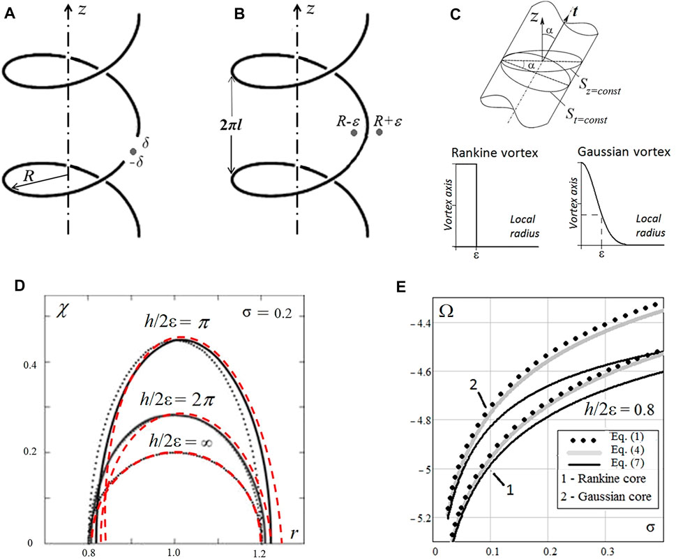
FIGURE 1. Sketch of the regularization of filament approximations in the development of the motion of a helical vortex by (A) the cutoff method and (B) the method of averaging the velocity in the vicinity of the singular filament; (C) Rankine and Gaussian vorticity of the finite vortex core. (D) Examples in the helical variable (r, χ = z + rθ/l) at St with different vortex pitches h/2ε = π; 2π; ∞ for the cross-sections of the vortex tubes of the touching vortex ring (dotted lines) in the first two methods and deformations of helical vortex tube in Dyson technique with Rankine (solid lines) and Gaussian distributions (dashed red lines). (E) Angular velocity of the helical vortex versus the size of its vortex core σ = ε/R, obtained using Eqs 1, 4, 7 with Rankine vortex distributions (curves 1) and Gaussian vortex distributions (curves 2).
In addition to the numerical cutoff method, there are two successful analytical techniques for determining the self-induced motion of helical vortices. These methods are based on regularization of the solution with respect to averaged velocities calculated at a finite distance (usually equal to the vortex core radius) from the singular filament (Figure 1B). The velocities in the vicinity of a whole helical filament can be determined using a transformation of the Biot–Savart integral to the sum of the Kapteyn series (Kawada, 1936; Hardin, 1982; Ricca, 1994; Fukumoto et al., 2015). A more accurate result allows one to obtain an approximation of the Kapteyn series with the pole and the logarithm (Okulov, 2004) separated from each component and explicitly summed, with a controlled error of neglected terms (Okulov and Sørensen, 2020). However, there is a difference between the self-induced velocity of a helical vortex with a finite core and the regularization given by calculating the average velocity at finite distances from the filament. One correction method uses the equivalent touching vortex rings, similar to the cutoff method. This representation of the helical vortex using touching vortex rings was proposed by Moore and Saffman (1972), and is hereinafter referred to as the VR (vortex ring) correction. This VR correction of the helical vortex via the equivalent vortex ring has been numerically simulated by Ricca (1994) and analytically substantiated by Boersma and Wood (1999). An alternative method (Fukumoto and Okulov, 2005) for the correction of the filament solution to the real vortex motion can also be established using the Dyson technique, developed as a description of Saturn’s rings (Dyson, 1893). It is also necessary to consider the possibility of different distributions of vorticity in the core of the helical vortex for these three approximations. Constant distribution (Rankine-type) of vorticity in the core (Figure 1C) was only used in our last comparison (Okulov and Fukumoto, 2021). Here, we will also add the Gaussian distributions to fully compare these three methods and two basic types of vorticity distributions with each other. However, the Rankine-type and Gaussian vorticity distributions in the core of helical vortices have not yet been compared. Note also that solutions given by the cutoff, MS, and Dyson methods were not compared in the comparison using the Gaussian vortex core.
Unfortunately for our comparisons, it is currently impossible to use experimental results—it is significantly more difficult to obtain reliable experimental data because the contact measuring techniques affect the motion of the vortex filament and because numerous averaging is required to determine the vortex structure (Okulov et al., 2019). However, the possibility of using alternative calculation methods for this comparison is quite real. Some of these comparisons have already been completed. For example, the approximation given by the cutoff method was compared with direct Navier–Stokes calculations over a wide range of helical pitches and vortex core sizes, albeit only with a Gaussian distribution of vorticity (Selçuk et al., 2017).
The purpose of this work is to compare the three methods and the two vortex distributions. In addition, we study the possibility of using these methods in cases where the dimensions of the vortex core are comparable to the distances between the elements of the vortex filaments or between the turns of the helical vortex. In the remainder of this mini-review, we present the final form of all three solutions and identify the differences when considering the Rankine and Gaussian distributions of vorticity in the cores of helical vortices. A comparison between all the considered solutions is presented, which will give a new impetus to the development of near wake modeling behind wind turbines and for other swirling flows with dominant helical vortices.
A helical vortex in an infinite space (Figures 1A–C) has the restriction that the size 2ε of the vortex core does not exceed the helix pitch h = 2πl. The vorticity described by the filament circulation Γ corresponds to a helical vortex with only an axial component of the vorticity, which can be described by a uniform (Rankine) or Gaussian distribution in the core along the local radius. The following relations are introduced to compare different regularization methods for calculating the angular velocity Ω of the self-induced motion of helical vortices (Okulov and Sørensen, 2020) using singular solutions for infinitely thin filaments (Figures 1A,B).
The cutoff method originally described by Crow (1970) has been used in many studies. In this article, the formulation of Alekseenko et al. (2007) is used. The expression for calculating the self-induced angular velocity in cylindrical coordinates (r, θ, z) has the form:
where the cutting length δС = εδ(•) is proportional to the vortex radius ε;
or a Gaussian vorticity core (Selçuk et al., 2017) that gives δ(•) = δG:
The upper limit of the integrals in Eq. 1 for N = 55 was fitted by the same ring, and together with Eq. 2 or Eq. 3 provides the required accuracy of calculations up to the fourth significant digit.
The second regularization method is based on the solution for a continuous helical filament in the form of a Kapteyn series. This series was derived by Kavada (1936) and Hardin (1982). As it is impossible to interrupt the vortex filament, the regularization is carried out not by cutting out a filament segment (Figure 1B), as in the cutoff method (Figure 1A), but by calculating the velocities in a certain vicinity of this filament (Ricca 1994). In Okulov (2004), the sums of the Kapteyn series are presented in the form of two singular terms, a pole and a logarithm, and together with the one main term of the regular remainder these ensure an error of less than 2% (Okulov and Sørensen 2020). In this study, the formula for the angular velocity, which includes the dimensionless helical pitch τ and the dimensionless core radius σ = ε/R, is:
Here,
or for the Gaussian vorticity with δ(•) = δG:
This is the first time that the values
The third method was initially proposed by Dyson (1893) for calculating the rings of Saturn. This approach was applied to the dynamics of helical vortices (Fukumoto and Okulov 2005), whereby the transition from a helical vortex tube to singular vortex filaments involved integrating the volume integral over the cross-section of the core using shift operators. As a result, the effect of a finite core in a volumetric integral is reduced to the development of linear integrals and is represented as the sum of multipole filaments (Fukumoto and Okulov 2005; Okulov and Fukumoto 2020):
where the main term
which is identical to Eq. 4, but without the term ln2δ(•). For the correction of different vorticity distributions in the finite vortex core in Eq. 7, the second dipole term
where
The term
The value d(•) = dG for the Gaussian vorticity was defined in Okulov and Fukumoto (2020) by fitting it to the numerical solution (Selçuk et al., 2017)
The next step uses only the two terms (pole and dipole) in Eq. 7 instead of the exact multipole expressions. Testing for the Rankine distribution of vorticity in the vortex core was carried out in Okulov and Fukumoto (2020) by comparison with the data of Boersma and Wood (1999), in which the integrals were calculated for the Biot–Savart law with an accuracy up to the eighth significant digit for several values of the pitch of the helical vortex. Figure 1 of Okulov and Fukumoto (2020) indicates a good correlation, demonstrating that the Dyson method is suitable for studying helical vortices.
The angular velocities of the self-induced rotation of a helical vortex with Γ = 1 given by the different methods are presented in Table 1 for the Rankine-type and the Gaussian vorticity distribution. The dimensionless helical pitch h/(2ε) changes from a very large value of 100 to an extremely small value that coincides with the size of the vortex core, 2ε. Despite the primary assumptions on which all three models are usually based (ε << L), a small pitch was applied in the calculations to establish when the results obtained by different methods begin to deviate from one another or from other baseline calculations. For example, the Selçuk et al. (2017) examined a helical vortex with a Gaussian core and found good correlations between direct Navier–Stokes simulations (DNS) and the cutoff method results using Eqs 1, 3 for dimensionless helical pitch values as small as h/(2ε) ≈ 2π. Below this value, the results of the cutoff method differed significantly from the DNS calculations, and the authors reasonably associated this with the impossibility of deforming the circular section of the frozen vortex core in the cutoff method, in contrast to the DNS calculations. Nevertheless, according to the data of Selçuk et al. (2017), we can consider the cutoff method as a standard for pitch values greater than 2π. Note that Eqs 1, 4, and 7 yield the same results up to the fourth significant digit for both Rankine and Gaussian vorticity distributions in the core (Table 1) for values greater than 2π.
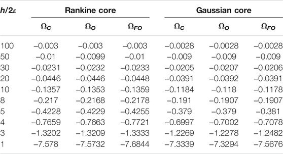
TABLE 1. Values of the angular velocity of the helical vortex of Rankine and Gaussian cores.
The minimal differences for pitch values greater than 2π are due to errors in the numerical integration of the Biot–Savart law for the finite section of N = 55 in Eq. 1; in neglecting the remainder terms in the approximation of the Kapteyn series in Eq. 4, and in the multipole development of the Dyson method in Eq. 7. Moreover, the results using both Eqs 1 and 4 are identical to within an acceptable error for all values of the pitch in Table 1. This is because the same frozen circular cross-section of the touching vortex ring is used in both methods, which gives the same approximations in Eqs 2, 5 or Eqs 3, 6. Both Eqs 1, 4 ignore the vortex core deformation when the turns of the helical vortex become closer to each other, whereas in the Dyson method, Eq. 7 gives better solutions because the dipole term describing the vortex core can be deformed in the case of small pitch values. Indeed, in Eq. 7, the core is described by adding a dipole singularity, which makes it possible to deform the vortex core through the deformation of the dipole as the turns of the helical vortex become compressed (Figure 1D).
In first two methods, the cross-sections of the touching vortex ring in the plane (r, χ) at z = 0 are elongated ellipses that coincide with the circle only for an infinite helical pitch (dotted lines in Figure 1D). In the third method, the forms of the cross-sections of the stream tubes are solutions of the equation Ψm + Ψd = const, where Ψm and Ψd are the stream functions determined by equations (59) and (76) from Fukumoto and Okulov (2005). The constant in the equation is the same for any values of the helical pitch found at an infinite one when the stream tube has a circular cross-section with radius ε. The core deformations in the model of Eq. 7 at the large pitch are insignificant and the significant one occurs when 5 < h/(2ε) < 8 (Figure 1 and Table 1). The effect correlates with data of the DNS calculations (Selçuk et al., 2017) for small pitches of the helical vortex.
The data in Figure 1E illustrate the large differences between the angular velocities for the Rankine and Gaussian distributions in the vortex core. These significant differences may cause the actual core size to decrease in the case of the Rankine vorticity distribution. The results obtained using the Dyson method with the Gaussian vorticity distribution are more accurate in determining the equilibrium states of rotating pairs of helical vortices, which have been intensively studied in terms of rotary vortex wakes (Delbende et al., 2015; Okulov 2016; Okulov 2020) or in more complex investigations of vortex dynamics (Taamallah et al., 2019; Dierkes et al., 2020).
In this study, three different methods of solving the problem of the motion of helical vortices with a finite core were reviewed and compared. The results indicate that the three methods give the same solution when the vortex pitch is at least six times the diameter of the vortex core. This result is in good agreement with DNS numerical simulations (Selçuk et al., 2017), which established that the cutoff method deviates from the correct solution for dimensionless helical pitches of less than 2π. At smaller pitches, the Dyson method has a definite advantage, and its use makes it possible to further refine the solution.
The data obtained in this study will supplement the existing knowledge on the description of elementary helical vortex structures. The comparisons made in this article are of interest for modeling the rotor wake behind wind turbines, describing central helical vortices in vortex devices, or when studying natural phenomena such as tornadoes.
Conceptualization, VO and YF; writing—original draft preparation, VO; writing—review and editing, VO and YF; supervision, VO and YF.
The simulation of helical vortices using the Dyson method and the regularization of the Kapteyn series was carried out with the financial support of the Bilateral Joint Program JSPS (Grant No. JPJSBP120214812) and the RFBR (Grant No. 21-58-50003); the approximation and data analysis of the cutoff methods was carried out by VLO under a contract with the Ministry of Education and Science of the Russian Federation (Contract No. 075-15-2019-1923).
The authors declare that the research was conducted in the absence of any commercial or financial relationships that could be construed as a potential conflict of interest.
All claims expressed in this article are solely those of the authors and do not necessarily represent those of their affiliated organizations, or those of the publisher, the editors and the reviewers. Any product that may be evaluated in this article, or claim that may be made by its manufacturer, is not guaranteed or endorsed by the publisher.
The authors would like to acknowledge the support from the Department of Wind Energy, Technical University of Denmark and Institute of Mathematics for Industry, Kyushu University.
Alekseenko, S. V., Kuibin, P. A., and Okulov, V. L. (2007). Theory of Concentrated Vortices: An Introduction. Germany: Springer-Verlag Berlin Heidelberg.
Boersma, J., and Wood, D. H. (1999). On the Self-Induced Motion of a Helical Vortex. J. Fluid Mech. 384, 263–279. doi:10.1017/s002211209900422x
Crow, S. C. (1970). Stability Theory for a Pair of Trailing Vortices. AIAA J. 8, 2172–2179. doi:10.2514/3.6083
Dierkes, D., Cheviakov, A., and Oberlack, M. (2020). New Similarity Reductions and Exact Solutions for Helically Symmetric Viscous Flows. Phys. Fluids 32 (5), 053604. doi:10.1063/5.0005423
Dyson, F. W. (1893). The Potential of an Anchor Ring. 2. Philos. Trans. Roy. Soc. Lond. Ser. A 184, 1041.doi:10.1098/rsta.1893.0020
Fukumoto, Y., and Okulov, V. L. (2005). The Velocity Field Induced by a Helical Vortex Tube. Phys. Fluids 17 (10), 107101. doi:10.1063/1.2061427
Fukumoto, Y., Okulov, V. L., and Wood, D. H. (2015). The Contribution of Kawada to the Analytical Solution for the Velocity Induced by a Helical Vortex Filament. ASME. Appl. Mech. Rev. 67 (6), 060801. doi:10.1115/1.4031964
Hardin, J. C. (1982). The Velocity Field Induced by a Helical Vortex Filament. Phys. Fluids 25 (11), 1949. doi:10.1063/1.863684
Kawada, S. (1936). Induced Velocity by Helical Vortices. J. Aeronaut. Sci. 3, 86–87. doi:10.2514/8.141
Moore, D. W., and Saffman, P. G. (1972). The Motion of a Vortex Filament with Axial Flow. Philos. Trans. Roy. Soc. Lond. Ser. A 272, 403.
Okulov, V. L. (2016). An Acentric Rotation of Two Helical Vortices of the Same Circulations. Regul. Chaot. Dyn. 21 (3), 267–273. doi:10.1134/s1560354716030035
Okulov, V. L., and Fukumoto, Y. (2020). Analytical Solution for Self-Induced Motion of a Helical Vortex with a Gaussian Core. Thermophys. Aeromech. 27 (4), 481. doi:10.1134/s0021894420030049
Okulov, V. L., and Fukumoto, Y. (2021). Singular Approximations for Calculating Vortex Filaments. J. Appl. Mech. Tech. Phy 62 (3), 519–524. doi:10.1134/s0021894421030196
Okulov, V. L., Kabardin, I. K., Mikkelsen, R. F., Naumov, I. V., and Sørensen, J. N. (2019). Helical Self-Similarity of Tip Vortex Cores. J. Fluid Mech. 859, 1084–1097. doi:10.1017/jfm.2018.850
Okulov, V. L., Naumov, I. V., Kabardin, I. K., Litvinov, I. V., Markovich, D. M., Mikkelsen, R. F., et al. (2021). Experiments on Line Arrays of Horizontal-axis Hydroturbines. Renew. Energ. 163, 15–21. doi:10.1016/j.renene.2020.08.148
Okulov, V. L. (2004). On the Stability of Multiple Helical Vortices. J. Fluid Mech. 521, 319–342. doi:10.1017/s0022112004001934
Okulov, V. L., and Sørensen, J. N. (2020). The Self-Induced Motion of a Helical Vortex. J. Fluid Mech. 883, 837. doi:10.1017/jfm.2019.837
Okulov, V. L., Sørensen, J. N., and Wood, D. H. (2015). The Rotor Theories by Professor Joukowsky: Vortex Theories. Prog. Aerospace Sci. 73, 19–46. doi:10.1016/j.paerosci.2014.10.002
Okulov, V. L. (2020). Vortex Pair of Coaxial Helical Filaments. J. Appl. Mech. Tech. Phy 61 (3), 343–349. doi:10.1134/s0021894420030049
Ricca, R. L. (1994). The Effect of Torsion on the Motion of a Helical Vortex Filament. J. Fluid Mech. 273, 241–259. doi:10.1017/s0022112094001928
Saffman, P. G. (1992). Vortex Dynamics. Cambridge, UK: Cambridge University Press. doi:10.1017/s0022112094001928The Effect of Torsion on the Motion of a Helical Vortex Filament
Selçuk, C., Delbende, I., and Rossi, M. (2017). Helical Vortices: Quasiequilibrium States and Their Time Evolution. Phys. Rev. Fluids 2, 084701.doi:10.1103/physrevfluids.2.084701
Sørensen, J. N., Mikkelsen, R., Troldborg, N., Okulov, V. L., and Shen, W. Z. (2013). “The Aerodynamics of Wind Turbines,” in Mechanics Down under. Editors J. Denier, and M. Finn (Dordrecht: Springer), 231–247. doi:10.1007/978-94-007-5968-8_15
Taamallah, S., Dagan, Y., Chakroun, N., Shanbhogue, S. J., Vogiatzaki, K., and Ghoniem, A. F. (2019). Helical Vortex Core Dynamics and Flame Interaction in Turbulent Premixed Swirl Combustion: A Combined Experimental and Large Eddy Simulation Investigation. Phys. Fluids 31 (2), 025108. doi:10.1063/1.5065508
Keywords: wind turbine, near wake, tip vortex, helical vortex, tornadoes
Citation: Okulov VL and Fukumoto Y (2022) Review of Analytical Approaches for Simulating Motions of Helical Vortex. Front. Energy Res. 10:817941. doi: 10.3389/fenrg.2022.817941
Received: 18 November 2021; Accepted: 25 January 2022;
Published: 15 February 2022.
Edited by:
Stefan Ivanell, Uppsala University, SwedenReviewed by:
Davide Astolfi, University of Perugia, ItalyCopyright © 2022 Okulov and Fukumoto. This is an open-access article distributed under the terms of the Creative Commons Attribution License (CC BY). The use, distribution or reproduction in other forums is permitted, provided the original author(s) and the copyright owner(s) are credited and that the original publication in this journal is cited, in accordance with accepted academic practice. No use, distribution or reproduction is permitted which does not comply with these terms.
*Correspondence: V. L. Okulov, dmFva0BkdHUuZGs=
Disclaimer: All claims expressed in this article are solely those of the authors and do not necessarily represent those of their affiliated organizations, or those of the publisher, the editors and the reviewers. Any product that may be evaluated in this article or claim that may be made by its manufacturer is not guaranteed or endorsed by the publisher.
Research integrity at Frontiers
Learn more about the work of our research integrity team to safeguard the quality of each article we publish.