 Junhong Hao
 Xing Gou1
 Qun Chen
- 1Key Laboratory for Thermal Science and Power Engineering of Ministry of Education, Department of Engineering Mechanics, Tsinghua University, Beijing, China
- 2State Grid Liaoning Electric Power Supply CO. LTD., Shenyang, China
The integration of high-efficiency heat pump and thermal storage devices is of great significance to realize the synergy between efficient and flexible operation of the integrated electric and thermal energy systems. This article proposed an integrated electric–thermal energy system with heat pump and thermal storage devices and introduced the heat current method for constructing its overall dynamic power flow model by considering energy transfer, conversion, and storage processes. On this basis, we derived the overall system constraint and component constraint equations. Under the objective of wind power curtailment minimization, the comprehensive effects of the dynamic characteristics of the heat pump, thermal storage capacity, new wind power installation, and new heat load on the electric and thermal output are analyzed. The results show that the dispatching accuracy of wind power output can be improved by up to 8% by taking into account the dynamic characteristics of the heat pump. The combination of heat pump and thermal storage device results in a leverage factor of 3.06 and 0.17 for the storage and release processes, respectively, effectively increasing the flexibility of system scheduling. The coordination between the newly added wind power installation and the added new heat load, with the higher operating temperature of the heat pump, is more conducive to promote wind power accommodation and improve the system’s overall flexibility. These results provide the necessary basis for the development of an integrated dispatch plan for the integrated electric and thermal energy systems containing the heat pump–thermal storage.
Introduction
With the increase of extreme weather, the sustainable and coordinated development of energy and environment has become an important topic of great concern (Sangster, 2016). Recently, many countries all over the world have put forward the carbon peak and carbon neutral energy development strategy. Taking China as an example, in order to achieve the dual carbon goals of carbon peak and carbon neutrality, it has been proposed to build a new power system with renewable energy as the main part, which will become the main developmental direction of energy fields in the future. With the rapid development of renewable energy and the continuous increase of installed capacity of wind power and photovoltaics, the renewable power accommodation will become more important. Meanwhile, the diversification of terminal energy consumption requires the utilization of electric heating, electric heat pumps, thermal storage, and other energy conversion devices on the energy consumption side, which will constitute an integrated electric and thermal energy system (IETE), becoming a key technical basis for the efficient operation and flexible dispatching of the new power system in the future.
The IETEs often involve different energy forms such as electrical and thermal energy and include the electric and heat subsystems, respectively. For example, the utilization of electric heat production and thermal storage technology in the IETEs can effectively improve the wind power accommodation, but the loss of the energy grade results in inefficiency of the energy utilization (Hao et al., 2020a). Compared to direct heat production by electric heating, an electric heat pump, which is of high efficiency, can improve the flexibility of the power system and promote the large-scale accommodation of renewable energy combining with a thermal storage device. Actually, the electric heat pump can simultaneously use low-grade thermal energy (absorbing heat from the external environment) and low-value renewable energy (abandoned wind, etc.) to improve the ability of electric and thermal energy conversion, providing an optional path to achieve a clean heat supply. On the other hand, the application of thermal storage can reconfigure energy consumption demands in the spatial and temporal ranges by shifting peaks and valleys, effectively regulating the peak and valley characteristics of electrical and thermal loads on the user’s side. Therefore, the heat pump–thermal storage devices can realize flexible controllability between energy supply and demand in new power systems (Bampoulas et al., 2021; Schellenberg et al., 2020).
The inclusion of an electric heat pump coupled with a thermal storage device in the IETEs ensures that the conversion efficiency can be further increased by thermal storage, thus improving the inertia of the system and enhancing the adjustability of the whole system (Bechtel et al., 2020). However, the inherent differences in quantitative and qualitative properties of electrical and thermal energy require a unified model for the collaboration of electrical and thermal energy, which is significant for the optimal dispatch and efficient operation of the IETEs. The application of heat pump–storage devices in the IETEs will moreover increase the difficulty of system analysis and modeling due to the large difference in time constants and the inconsistent inertia of the electric and thermal systems (Franco and Salza, 2011; Liu et al., 2011). Therefore, it is necessary to fully consider the coupling relationship and time scale between each component and carry out simulations of the dynamic characteristics of non-linear components to match the actual system operation as much as possible for the application of high-efficiency heat pump–thermal storage in the IETEs.
Recently, many scholars have conducted studies on static models of external characteristics, simplified dynamic models, and multivariate black-box regression models of heat pumps for integrated electric and thermal energy systems (Lee and Lu, 2010; Pan et al., 2017). For example, Tahir et al. (2019) constructed an exogenous dynamic model of heat pumps based on the energy hub model for multiple energy production and consumption systems by directly considering the input and output power of heat pumps to analyze the demand, response, and renewable energy consumption of integrated energy systems in domestic regions. The same heat pump exogenous characteristic model was also applied to the optimal operation of other integrated energy systems containing renewable energy (Song et al., 2017; Wanjiru et al., 2017). Meanwhile, Lu, (2012) simplified the equivalent thermodynamic model of electric heat pumps and then proposed a voltage optimization strategy combining day-ahead optimal scheduling and intraday real-time regulation of electric heat pumps. Zhang et al. (Menglin et al., 2021) constructed a model of a large heat pump and implemented optimization for electric and thermal systems containing large heat pumps to gradually balance the prediction errors of renewable energy and load and achieved the synergistic optimization of standby heat regulation. On the other hand, Gao et al. (2021) tested the operational performance of a ground source heat pump system under typical operating conditions, calculated and studied the performance indicators of the system, and made recommendations to improve the operational performance of the GSHP system in terms of system design, construction, and operation.
The above modeling and analysis of IETE with a heat pump and thermal storage requires further consideration of the different energy characteristics and transport properties of electrical and thermal energy at different time scales. However, the mutually independent research perspectives of electricity based on power flow and heat based on work mass flow (Verda and Colella, 2011), which further increases the complexity of dynamic modeling and analysis under multiple time scales. Two different perspectives become the key challenge of the synergistic efficiency and flexibility of the IETEs with heat pump–thermal storage (Hongbin et al., 2016; Liu et al., 2016). In recent years, the heat current method has been proposed to provide a new research idea for the overall modeling and optimization analysis of heterogeneous power flow systems such as electricity and heat (Chen et al., 2017). The method proposes a quasi-Ohm law to characterize the heat-transfer process from the perspective of thermoelectric analogy and also proposes and derives the definition and expressions for the generalized thermal resistance of heat-transfer equipment (Hao et al., 2021), which enables the electrification characterization of different systems such as heat-transfer systems (Hao et al., 2020b; He et al., 2020), thermal systems (Hao et al., 2018; Li et al., 2019), and integrated energy systems (Dai et al., 2017a; Hao et al., 2020a; Wang et al., 2021) through the linearized definition of the heat-transfer process, and provides a new perspective for the IETEs to achieve integrated modeling and global optimization.
In this article, we propose an integrated electrical and thermal energy system with heat pump and thermal storage devices and then apply the heat current method to construct an overall power flow model of the IETEs that takes into account the dynamic characteristics of the heat pump and thermal storage device. Under the optimization objective of minimizing wind power curtailment, we analyzed the influences of dynamic performance of the heat pump, the new wind power installed capacity, the new heat load, and the maximum operation temperature of the heat pump on the wind power accommodation.
IETEs With a Heat Pump and Thermal Storage
Physical Model of the System
The IETEs contain different types of energy production methods and various energy utilization methods such as electricity and heat. As shown in Figure 1, the supply side of energy includes various plant types to generate electric and heat power: thermal power units (TP), wind power (WP), new installed wind power (nWP), and combined heat and power (CHP) units. The electricity produced by different units is transmitted to users through the grid to meet their different electrical load (EL-1, EL-2, and EL-3) demands, while the CHP units simultaneously produce heat to meet the heat load (HL) of existing centralized heat users through heat-exchange stations (HX2). At the same time, in order to accommodate wind power and promote clean heat supply for end users, this article introduces the electric heat pump (HP) and thermal energy storage device (TES) on the basis of the existing IETEs so as to meet the new heat load (nHL) of users on the demand side and realize efficient and clean heat supply.
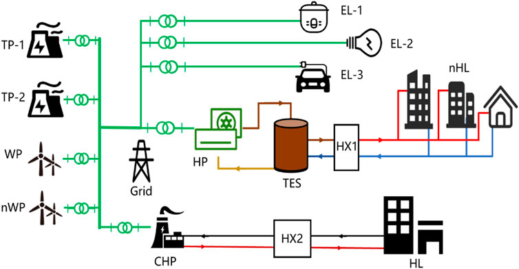
FIGURE 1. Sketch of the IETEs with the heat pump–thermal storage device.
Through the application of electric heat pump–thermal storage coupling devices so that part of the electrical energy can be converted into heat through the electric heat pump device, heating the storage medium in the thermal storage device utilizing the circulating working fluid, satisfying the user’s new heat load by the heat exchanger (HX1) between the thermal storage device and the user, achieving the flexible decoupling of heat generation and heat supply, and constructing a flexible heating mode of electric heat production, thermal storage, and heat demand can be realized.
Heat Current Model of Heat Pump–Thermal Storage and Heat Supply
For the IETEs with heat pump–storage shown in Figure 1, it covers the production, transmission, storage, and utilization of electrical and thermal energy, in which the production and transmission processes of thermal energy are very different from electrical energy. In order to realize the overall modeling and analysis of electric energy transmission, electro-thermal conversion, thermal storage, and heat transfer, this article introduces the heat current method to analyze the performance and overall modeling of the coupled heat pump–storage device. Utilizing electric power, the heat pump also absorbs heat from the environment and then jointly heats the medium in the thermal energy storage device, which involves the heat-transfer processes and the conversion processes between electric power and thermal power. Furthermore, the thermal storage device mainly contains two processes of thermal storage and heat transfer, which are related to the temperature of the medium in the thermal storage device. When the mass of the medium in the thermal storage device is given, in a limited temperature range, the thermal energy storage and release processes of the device can be analogously equated to the charging and discharging processes of capacitive elements in electricity. That is, it can be described by the product of the change in temperature of the thermal storage medium over time and its total heat capacity. It should be noted that both electric heat pumps and storage devices are involved in the heat-transfer process of the heat-transfer equipment. The rate of heat transfer is limited not only by the area of the heat-transfer equipment but also by the equipment to drive the heat-transfer medium, such as limited pump performance, that is, the restrictions on the circulation flow of the heat-transfer medium. In the analysis of this article, it is considered that the thermal storage device, work material transport pipeline, etc. have good insulation, and the heat loss of the thermal storage device and pipeline can be ignored.
Applying the heat current method to different heat-transfer devices, a standardized thermal resistance model is utilized (Hao et al., 2021), where the driving potential of the heat-transfer process is the inlet temperature of the fluid on the high temperature side (Th, in) and the inlet temperature of the fluid on the low temperature side (Tc, in), and the ratio of the inlet temperature difference between the two fluids and the amount of heat exchanged is the heat-transfer thermal resistance, which is expressed as
where NTUh=(φKA)/Gh, NTUc=(φKA)/Gc. φ is a correction factor introduced by the different types of heat exchangers, K is the heat-transfer coefficient of the heat exchanger, A is total heat-transfer area, and the product of the three (φKA) is the effective thermal conductance of the heat exchanger. Gh is the heat capacity flow of the hot-side fluid in the heat-exchange equipment, that is, the product of the mass flow rate (mh) and the specific heat capacity (cp). Gc is the heat capacity flow of the cold-side fluid in the heat-exchange equipment, that is, the product of the cold side fluid mass flow rate (mc) and specific heat capacity (cp). The standardized thermal resistance model is like an electrical resistance.
Based on the fluid flow typology of the heat pump–thermal energy storage device and heat supply subsystem, we can construct its heat current model using the aforementioned standardized thermal resistance model and the modeling method (Chen et al., 2017). The heat current model includes the physical processes of a heat pump, a thermal storage device, a heat exchanger, and three buildings. There are two streams of power flowing into the system; one is the compressor power consumption that is from the electrical grid, Peh, and raising the temperature Te to Tc by the compressor, and the other one is from the ambience through the evaporator in the heat pump. Re and Rc are the thermal resistances of the evaporator and condenser in the heat pump, respectively. Rs is the thermal resistance of the heat exchanger (HX1) for supplying heat to satisfy the new heat load. Rb is the thermal resistance of the heat exchanger in each building between the supply water and the ambience. Te and Tc are the evaporation temperature and condenser temperature, respectively. Ts is the storage temperature of the thermal storage device. Tr is the return water temperature. Tsu is the temperature of the supply water for users. Ta is the ambient temperature. The equivalent thermal capacity, C, presents the thermal storage and release processes by the temperature variation with the time.
Power Flow Model of the IETEs
Based on Figure 1, this research uses the six-bus power system model and direct current (DC) power flow model (Dai et al., 2017b; Hao et al., 2020a) for describing the power system shown in Figure 2. In this model, P is the input power and xi,j is the power line reactance between bus i and bus j. θ is the voltage angle of the bus. The computational equations based on the direct current power flow model of the power system are introduced in Ref. Hao et al., 2020a.
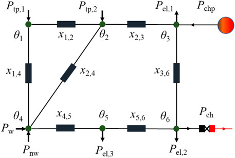
FIGURE 2. DC power flow model of a six-bus power system (Hao et al., 2020a).
Figure 3 shows that the heat power flows in the heat current model based on the thermoelectric analogy perspective by introducing the equivalent capacitance and generalized resistance as a way to achieve an electrification representation of thermal energy conversion, storage, and transfer in heat pumps, thermal storage devices, heat exchangers, and other devices, which provide the necessary basis for the construction of an overall power flow model of the IETEs. Therefore, combining the heat current model and the DC power flow model can construct the overall power flow model of the IETEs with heat pump–thermal storage, as shown in Figure 4. The black line means the electric power, and the yellow line means the heat current. Herein, the heat generated from the CHP unit can provide the original heat load by the thermal resistance Rb. This overall model covers multiple coupling processes such as electrical energy, thermal energy transport, and electro-thermal conversion in the electric heat pump, thermal storage process, and energy transport processes. It provides the foundation for the comprehensive analysis of the system and the construction of system constraints from the power flow perspective.
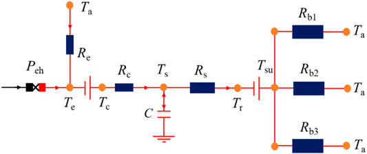
FIGURE 3. Heat current model of the heat pump–thermal energy storage–heat supply.
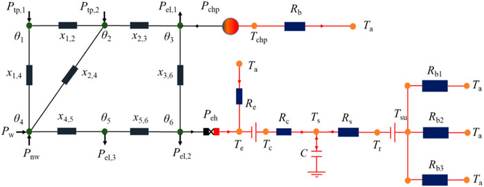
FIGURE 4. Power flow model of the IETEs with the heat pump and thermal storage device.
System Constraints and Optimization
System Constraints
Based on the overall power flow model of the system in Figure 4, the power balance equation for the entire system can be constructed as follows
where, Ptp and Pw are the thermal power and wind power, respectively, Pnw is the new wind power, and Pchp is the electric output of the CHP unit. Pel is the electric load of the whole system, and Peh is the new electric load due to the addition of the electric heat pump coupling thermal storage device, and its calculation formula is
where M is the total mass of water in the thermal storage device and cp is the specific capacity of water in the thermal storage device. Ta is the ambient temperature, Te is the evaporation temperature of the evaporator in the electric heat pump, Ts is the total set temperature of the thermal storage device, Tr is the temperature of the return water on the user side, Re is the thermal resistance of the evaporator, and Rs is the thermal resistance of the intermediate heat release device when the thermal storage device supplies heat to the user.
Unit Constraints
Under given meteorological conditions, the wind power generation unit has the maximum power output; that is, the wind power output meets
where Pw, max is the maximum electric output of the wind power plant. Pw(t) represents the real-time electric output of the wind power, and this constraint is also applicable to the new wind power plant.
For the thermal plant units, due to capacity and regulation limitations, there are maximum and minimum outputs and climbing rates during the operation of thermal power units. The following constraints need to be satisfied for two thermal power plants
where Ptp, min and Ptp, max are the minimum and maximum outputs of the thermal power unit, respectively. Dtp, max and Utp, max are the maximum values of down- and up-ramp rates during the operation of the thermal power unit, respectively.
For the CHP unit, according to the typical “heat-led” operation mode, the ratio of electric output to thermal output of a cogeneration unit in normal operation is a constant value
where c is the heat to power ratio and Hchp is the heat output of the CHP unit.
Meanwhile, the heat generated from the CHP unit is used for satisfying the original heat load of users, which can be expressed as
where Tchp is the supply heat temperature of the CHP unit. Rb is a comprehensive thermal resistance containing the heat station (HX1) and the heat exchanger of the building. Qhl is the original heat load of residents.
For the future new heat load, the new heat load ratio is introduced
where α is the proportion of new heat load.
In this study, the electric power system, electric heat pump, thermal storage device, thermal storage and heat exchange device, and heat release and heat exchange device all have different time scales with characteristic time variations from a microsecond to minute scale. By comparison, the response time of the thermal storage process is the longest. Therefore, the dynamic modeling of the power system can only consider the transient stabilization process caused by the change in the user’s electrical load, which is comparable to the response time scale of the thermal storage process, while the delay characteristics of the pipeline and the dynamic characteristics of the heat exchanger can be ignored for the time being. Besides, the analysis is complicated when considering the dynamic performance of heat pump equipment such as evaporators and condensers, so we introduce performance factors to analyze the dynamic characteristics of the heat pump. On this basis, Eq. 3 can be rewritten as
where the coefficient of performance (COP) is an important parameter for presenting the electricity-heat conversion ability of the heat pump. Based on the definition of COP, that is, the ratio of the total generated heat to the electrical energy consumption, can be expressed as
where Qh is the total generated heat. Based on Eq. 12, we can find that COP varies with the ambient temperature, evaporation and condensation temperatures, the temperature of the thermal storage device, and the thermal resistance of the condenser and evaporator. Actually, the article considers that the evaporating temperature, the condensing temperature, and the temperature of the thermal storage device do not vary much, and the ratio of the thermal resistance of the condenser to that of the evaporator can be approximated as 1, the value of COP, which characterizes the dynamic characteristics of the heat pump, and can be approximated as a function of the ambient temperature, which varies with the ambient temperature.
At the same time, the heat-transfer constraint must be satisfied when providing heat to the user
where Tu is the return water temperature of the customer’s water supply and Rs is the thermal resistance. Given the performance of the water supply circulating pump, its circulating water flow rate also needs to satisfy the constraint that
For the medium water in the thermal storage device, on one hand, it is necessary to guarantee that no vaporization occurs at a given pressure and the temperature is lower than the maximum temperature that the heat pump can provide, and at the same time, it is necessary to meet the heat load to the additional users. Therefore, its operating temperature Ts cannot exceed the minimum of its saturation temperature at the operating pressure and the maximum temperature of the heat pump and is higher than the user’s return water temperature to ensure the supply of heat to the user
Optimization Objective and Given Conditions
With the rapid development of renewable energy, the accommodation of wind power and photovoltaics will moreover be highlighted in future power systems. Therefore, this article takes the minimum of wind curtailment as the optimization objective, and the expression of the objective is
For thermal power units, the maximum value of the thermal power unit is 1000 MW, and the minimum value is 50% of the rate power. The ramp rates of two thermal power units are the same, 40 MW/min. Besides, the range of power generation of the CHP unit is 180–400 MW. For the thermal storage device, the heat capacity of the thermal storage medium Mcp is 30,000 MJ/K, and the thermal conductance of the intermediate heat exchanger is 10 MW/K. The initial temperature of the heat exchanger is 85°C. For the circulating water pump, the upper and lower limits of circulating water mass flow rate are 300 kg/s and 100 kg/s, respectively. The user return water temperature (Tr) is 45°C. For the new users, the heat capacity flow of the user return water is 1 MW/K. The new heating load is 20% of the original load. The COP of the heat pump without considering the dynamic characteristics is set as a constant 1.6. Figure 5 shows the electrical load, the original heat load, and the wind power ceiling in a typical day with a 15-min time interval (Hao et al., 2020a). Meanwhile, Figure 6 gives the ambient temperature and COP obtained by the ambient temperature in a typical day. The COP of the electric heat pump has the same trend of change with the outdoor ambient temperature.
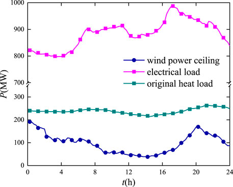
FIGURE 5. Variations of electrical and heat loads and the wind power ceiling in a typical day.
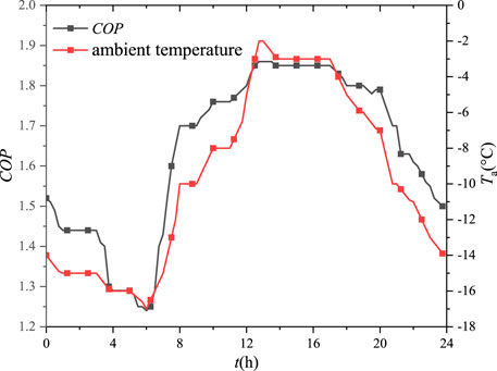
FIGURE 6. Variations of ambient temperature and COP in a typical day.
According to the given overall constraints and known parameters of the IETEs with heat pump–thermal storage, the article uses the Matlab software, combined with CPLEX and YALMIP optimization toolboxes, to minimize the abandoned wind power and analyze the optimal scheduling results of the system under different operational conditions.
Results and Discussion
Dynamic Characteristic Analysis of the Heat Pump
Combined with the dynamic characteristics of the electric heat pump, the fluctuation curve of the newly added heat load and the corresponding electric power after the application of the heat pump is given in Figure 7. The newly added heat load is 1,130.96 MWh, and the corresponding newly added electric load value is 702.94 MWh. It can be seen that the fluctuation curve of the heat load is gentler, while the fluctuation of the electric load curve is different from that of the heat load due to the dynamic characteristics of the electric heat pump, and its maximum deviation of peak and valley is directly increased by 63% without adding a thermal storage device. This shows that the asynchronous electrical and heat loads’ peak-shifting characteristics caused by the dynamic characteristics of the electric heat pump will influence the normal operation of the grid.
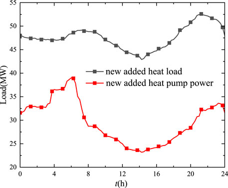
FIGURE 7. Fluctuation curve of the newly added heat load and the corresponding electric power after introducing the electric heat pump.
Figure 8 compares and analyzes the impact of the dynamic characteristics of the electric heat pump on the optimal dispatch when the newly added heat load is 20% and the new wind power is not installed. When the dynamic characteristics of the heat pump are not considered, the wind power output on a typical day is 2,109.16 MWh without adding thermal storage devices, and the total wind power output on a single day after considering the dynamic characteristics is 2,132.54 MWh, with a difference of 23.38 MWh between the two total output results. Meanwhile, the maximum deviation of local power reaches up to 8.0%. That is, the dynamic characteristics of the heat pump will impact the total wind power generation and the local power dispatch. It can be seen that when environmental factors are taken into account, it is beneficial to improve the accuracy of wind power output scheduling.
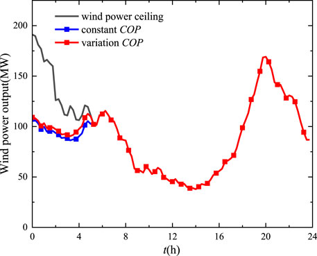
FIGURE 8. Influences of the dynamic characteristics of the heat pump on wind power output.
The effect of the thermal storage device on the electricity consumption of the electric heat pump is further compared and analyzed in Figure 9 when the dynamic characteristics of the electric heat pump are considered. It can be seen from the figure that the effect on the power consumption of the electric heat pump when adding the thermal storage device is reflected in two stages: heat storage and heat release. In the heat storage stage, such as 0–5.25 h in the figure, the thermal storage device can consume more power, which produces a certain leverage effect. Therefore, we propose a leverage factor, defined as the ratio of the power consumption of an electric heat pump with heat storage to the power consumption of an electric heat pump without heat storage, to quantify the leverage effect. It is found that the maximum leverage coefficient is 3.06 in the heat storage stage, and the minimum leverage coefficient is 0.167 in the heat release stage. Meanwhile, the maximum peak-to-valley deviation of the power consumption of the electric heat pump increases by a factor of 6 in the case of adding thermal storage and improving the scheduling flexibility of the power system.
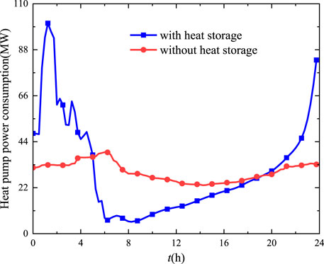
FIGURE 9. Power consumption curve of the electric heat pump in a typical day.
New Added Wind Power Installed Capacity Influence
In order to achieve the goal of China’s dual carbon strategy, the installed capacity of renewable energy will be further increased in the future as a proportion of the installed capacity of each energy source. Therefore, this article analyzes the operation of electric heat pumps with respect to the output characteristics of different units at different new wind power installations. Figure 10 shows the output of thermal power at three different newly installed capacities. Initially, the total thermal power output is 14,667.76 MWh, and when the installed wind power capacity increases by 20%, the thermal power output decreases to 14,354.59 MWh, which is 313.17 MWh lower than the original one, and when the installed wind power capacity increases by 40%, the thermal power output decreases to 14,055.59 MWh, which is 612.17 MWh lower than the original one. In other words, for the increase of installed wind power capacity and wind power output, the thermal power output decreases, which can effectively reduce coal combustion, save fossil energy, and reduce carbon emission in this case. Figure 11 gives the effect of the increase of the new capacity of wind power on the power consumption of the heat pump. Under different new wind power installed capacities, the electrical power consumption caused by the heat pump increases from 442.93 MWh to 448.73 MWh. Meanwhile, the optimal dispatch curve is also influenced.
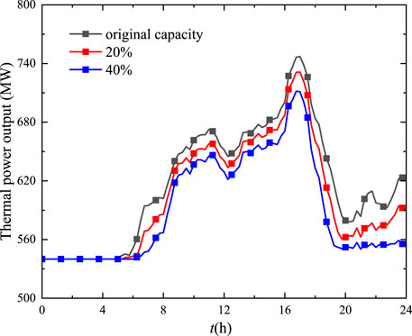
FIGURE 10. Thermal power generation under different new wind power installed capacities.
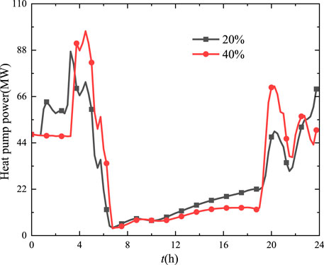
FIGURE 11. Variations of power consumption of the heat pump varying with the new wind power installed capacity.
New Added Heat Load Influence
In addition, clean heat supply has become a key technology to meet the growing heat load demand. Figure 12 gives the electricity consumption of the electric heat pump at different proportions of a new heat load. When the proportion of the new heat load increases from 10 to 30%, the electricity consumption of electric heat pump then increases by nearly 2.78 times, and the maximum leverage factor can reach 3.67 with the increase of the heat load. That is, the introduction of the electric heat pump for clean heat supply can effectively improve the wind power consumption capacity of the IETEs.
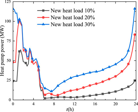
FIGURE 12. Heat pump power under different new heat loads.
Moreover, Figure 13 gives the wind power generation under different new heat loads. The wind power ceiling is 2,298.59 MWh. When 10% heat load is added, the actual output of wind power after adding the thermal storage device is 2,169.35 MWh, with 129.24 MWh of abandoned wind and 6.0% of abandoned wind rate. When the new 20% thermal load is added, the actual wind power output is 2,251.67 MWh with 46.92 MWh and a 2.1% abandonment rate. When the new load increases by 30%, the wind power output coincides with the wind power limit after adding the thermal storage device, and the wind power disposal volume has reached zero at this time, making the wind power completely consumed. That is, the addition of a new heat load can improve the wind power accommodation utilizing heat pump and thermal storage devices.
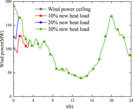
FIGURE 13. Wind power generation under different new heat loads.
Figure 14 gives the variation of thermal resistance of the heat release process with the temperature variation of the electric heat pump coupled with the thermal storage device under different new heat loads. The thermal resistance of the heat exchanger and the storage temperature have the same trend with the increase of the heat load. The larger the new heat load, the lower the thermal resistance of the heat exchanger, which requires better performance of the heat exchanger to meet the demand of the new heat load.
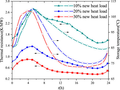
FIGURE 14. Thermal resistance and storage temperature varying with new heat loads.
Heat Pump Maximum Temperature Influence
For the heat pump–thermal storage device, the condensing temperature of the heat pump will be the key parameter to the temperature of the storage unit. Figure 15 gives the influence of the maximum condensing temperature of the heat pump on the wind power accommodation. When the maximum temperature of the heat pump increased from 100 to 110°C, the amount of abandoned wind power decreased from 104.73 MWh to 46.92 MWh, while the corresponding abandonment rate decreased from 4.8 to 2.1%. It can be concluded that the higher the condensing temperature of the heat pump, the easier the consumption of wind power and the smaller the wind abandonment rate. However, the higher temperature means the higher performance requirement of the electric heat pump, which will lead to a cost increase. Moreover, Figure 16 shows that the power consumption of the heat pump has the same variation trend at different maximum temperatures. From 0 to 6 h, the heat pump power increases and then decreases. From 6 to 24 h, the heat pump power will increase. The local leverage factor increases from 1.69 to 3.19 at t = 1.5 h when the maximum temperature increases.

FIGURE 15. Variations of wind power under different maximum temperatures.
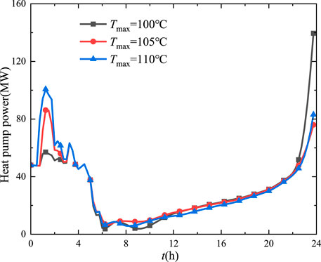
FIGURE 16. Variations of heat pump power under different maximum temperatures.
Conclusion
The high-efficiency electricity–heat conversion technology and thermal storage devices are significant for the development and utilization of renewable energy. This contribution proposed an integrated electrical and thermal energy system combining the heat pump and thermal storage device. Based on the heat current method, we built an overall dynamic power flow model for the IETEs containing the heat pump and heat storage, taking into account different processes in the system such as power balance, electric–thermal conversion, heat transfer, and storage. With the optimization objective of minimizing the wind power curtailment, the scheduling optimization of the whole system is carried out by synergistically considering the efficiency and flexibility.
The optimization results show that considering the dynamic characteristics of the electric heat pump affects the optimized scheduling results up to 8%. Coupling the heat pump and thermal storage will produce a leverage effect on the electric and thermal power output, which can reach 3.06 and 0.17 in the heat storage and heat release stages, respectively. That is, the heat pump–thermal storage can effectively enhance the flexible regulation capability of the IETEs. Finally, we analyzed and elucidated influence of the newly added wind power installation, newly added heat load, and the maximum condensing temperature of the electric heat pump on wind power accommodation under different circumstances. The future application of wind power for clean heat supply is a feasible technical solution, and the development of a more efficient electric heat pump coupled with a thermal storage device is the key to implementing this solution. Meanwhile, the most suitable electric heat pump should be selected as the electricity–heat conversion technology used in the IETEs. In summary, the application of the heat current method to analyze the dynamic characteristics of the heat pump and thermal storage is feasible and significant in the IETEs.
Data Availability Statement
The original contributions presented in the study are included in the article/Supplementary Materials, further inquiries can be directed to the corresponding author.
Author Contributions
JH: software, methodology, data curation, validation, conceptualization, methodology, and funding acquisition. XG: data curation, validation, and writing–review and editing. SW: project administration and writing–original draft. QC: investigation and visualization. KG: investigation.
Funding
The authors would like to thank the Science and Technology Projects of State Grid Corporation of China under Project (Grant No. 5400-202028125A-0-0-00).
Conflict of Interest
The authors WS and GK are employed by State Grid Liaoning Electric Power Supply CO., LTD. This study received funding from State Grid Corporation of China. The funder had the following involvement with the study integrated electrical and thermal energy system.
The remaining authors declare that the research was conducted in the absence of any commercial or financial relationships that could be construed as a potential conflict of interest.
Publisher’s Note
All claims expressed in this article are solely those of the authors and do not necessarily represent those of their affiliated organizations or those of the publisher, the editors, and the reviewers. Any product that may be evaluated in this article or claim that may be made by its manufacturer is not guaranteed or endorsed by the publisher.
References
Bampoulas, A., Saffari, M., Pallonetto, F., Mangina, E., and Finn, D. P. (2021). A Fundamental Unified Framework to Quantify and Characterise Energy Flexibility of Residential Buildings with Multiple Electrical and thermal Energy Systems. Appl. Energ. 282, 116096. doi:10.1016/j.apenergy.2020.116096
Bechtel, S., Rafii-Tabrizi, S., Scholzen, F., Hadji-Minaglou, J.-R., and Maas, S. (2020). Influence of thermal Energy Storage and Heat Pump Parametrization for Demand-Side-Management in a Nearly-Zero-Energy-Building Using Model Predictive Control. Energy and Buildings 226, 110364. doi:10.1016/j.enbuild.2020.110364
Chen, Q., Hao, J.-H., and Zhao, T. (2017). An Alternative Energy Flow Model for Analysis and Optimization of Heat Transfer Systems. Int. J. Heat Mass Transfer 108, 712–720. doi:10.1016/j.ijheatmasstransfer.2016.12.080
Dai, Y., Chen, L., Min, Y., Chen, Q., Hu, K., Hao, J., et al. (2017a). Dispatch Model of Combined Heat and Power Plant Considering Heat Transfer Process. IEEE Trans. Sustain. Energ. 8 (3), 1225–1236. doi:10.1109/tste.2017.2671744
Dai, Y., Chen, L., Min, Y., Chen, Q., Zhang, Y., Xu, F., et al. (2017b). Active and Passive thermal Energy Storage in Combined Heat and Power Plants to Promote Wind Power Accommodation. J. Energ. Eng. 143 (5), 04017037. doi:10.1061/(asce)ey.1943-7897.0000466
Franco, A., and Salza, P. (2011). Strategies for Optimal Penetration of Intermittent Renewables in Complex Energy Systems Based on Techno-Operational Objectives. Renew. Energ. 36 (2), 743–753. doi:10.1016/j.renene.2010.07.022
Gao, B., Zhu, X., Yang, X., Yuan, Y., Yu, N., and Ni, J. (2021). Operation Performance Test and Energy Efficiency Analysis of Ground-Source Heat Pump Systems. J. Building Eng. 41. doi:10.1016/j.jobe.2021.102446
Hao, J.-H., Ge, W.-C., Chen, Q., He, K.-L., Luo, H.-H., and Zhou, G.-P. (2018). Power Flow Method-Based Integrated Modeling and Optimization for Building Heat Transport and Gas Refrigeration System. J. Energ. Eng. 144 (5), 04018060. doi:10.1061/(asce)ey.1943-7897.0000577
Hao, J., Chen, Q., He, K., Chen, L., Dai, Y., Xu, F., et al. (2020a). A Heat Current Model for Heat Transfer/storage Systems and its Application in Integrated Analysis and Optimization with Power Systems. IEEE Trans. Sustain. Energ. 11 (1), 175–184. doi:10.1109/tste.2018.2888483
Hao, J., Chen, Q., Li, X., and Zhao, T. (2021). A Correction Factor-Based General Thermal Resistance Formula for Heat Exchanger Design and Performance Analysis. J. Therm. Sci. 30 (3), 892–901. doi:10.1007/s11630-021-1369-8
Hao, J., Zhang, Y., and Xiong, N. (2020b). The Integrated Component-System Optimization of a Typical Thermal Management System by Combining Empirical and Heat Current Methods. Energies 13 (23), 6347. doi:10.3390/en13236347
He, K.-L., Chen, Q., Ma, H., Zhao, T., and Hao, J.-H. (2020). An Isomorphic Multi-Energy Flow Modeling for Integrated Power and thermal System Considering Nonlinear Heat Transfer Constraint. Energy 211, 119003. doi:10.1016/j.energy.2020.119003
Hongbin, S., Zhaoguang, P., and Qinglai, G. (2016). Energy Management for Multi-Energy Flow: Challenges and Prospects. Automation Electric Power Syst. 40 (15), 1. doi:10.7500/AEPS20160522006
Lee, T.-S., and Lu, W.-C. (2010). An Evaluation of Empirically-Based Models for Predicting Energy Performance of Vapor-Compression Water Chillers. Appl. Energ. 87 (11), 3486–3493. doi:10.1016/j.apenergy.2010.05.005
Li, X., Chen, Q., Hao, J.-H., Chen, X., and He, K.-L. (2019). Heat Current Method for Analysis and Optimization of a Refrigeration System for Aircraft Environmental Control System. Int. J. Refrigeration 106, 163–180. doi:10.1016/j.ijrefrig.2019.06.004
Liu, W., Lund, H., and Mathiesen, B. V. (2011). Large-scale Integration of Wind Power into the Existing Chinese Energy System. Energy 36 (8), 4753–4760. doi:10.1016/j.energy.2011.05.007
Liu, X., Wu, J., Jenkins, N., and Bagdanavicius, A. (2016). Combined Analysis of Electricity and Heat Networks. Appl. Energ. 162, 1238–1250. doi:10.1016/j.apenergy.2015.01.102
Lu, N. (2012). An Evaluation of the HVAC Load Potential for Providing Load Balancing Service. IEEE Trans. Smart Grid 3 (3), 1263–1270. doi:10.1109/tsg.2012.2183649
Menglin, Z., Qiuwei, W., Jinyu, W., Xizhen, X., Zhongwei, L., and Fang, F. (2021). Real-time Optimal Operation of Integrated Electricity and Heat System Considering reserve Provision of Large-Scale Heat Pumps. Energy 237.
Pan, Z., Guo, Q., and Sun, H. (2017). Feasible Region Method Based Integrated Heat and Electricity Dispatch Considering Building thermal Inertia. Appl. Energ. 192, 395–407. doi:10.1016/j.apenergy.2016.09.016
Sangster, A. J. (2016). Massive Energy Storage Systems Enable Secure Electricity Supply from Renewables. J. Mod. Power Syst. Clean. Energ. 4 (4), 659–667. doi:10.1007/s40565-016-0204-9
Schellenberg, C., Lohan, J., and Dimache, L. (2020). Comparison of Metaheuristic Optimisation Methods for Grid-Edge Technology that Leverages Heat Pumps and thermal Energy Storage. Renew. Sustain. Energ. Rev. 131, 109966. doi:10.1016/j.rser.2020.109966
Song, Y., Hu, W., Zhang, Z., Hu, R., Huang, Q., and Chen, Z. (2017). “Optimal Operation and Location of Heat Pumps in the Integrated Energy systems.” in 2017IEEE Conference on Energy Internet and Energy System Integration (EI2), Beijing, China, November 26–28, 2017. IEEE, 1–6.
Tahir, M. F., Haoyong, C., Mehmood, K., Ali, N., and Bhutto, J. A. (2019). Integrated Energy System Modeling of China for 2020 by Incorporating Demand Response, Heat Pump and thermal Storage. Ieee Access 7, 40095–40108. doi:10.1109/access.2019.2905684
Verda, V., and Colella, F. (2011). Primary Energy Savings through thermal Storage in District Heating Networks. Energy 36 (7), 4278–4286. doi:10.1016/j.energy.2011.04.015
Wang, Y., Zhang, Y., Hao, J., Pan, H., Ni, Y., Di, J., et al. (2021). Modeling and Operation Optimization of an Integrated Ground Source Heat Pump and Solar PVT System Based on Heat Current Method. Solar Energy 218, 492–502. doi:10.1016/j.solener.2021.03.003
Wanjiru, E. M., Sichilalu, S. M., and Xia, X. (2017). Optimal Operation of Integrated Heat Pump-Instant Water Heaters with Renewable Energy. Energ. Proced. 105, 2151–2156. doi:10.1016/j.egypro.2017.03.607
Nomenclature
A Heat-transfer area, m2
c Heat to electricity ratio cold, condenser
COP Coefficient of performance
cp Specific heat capacity, W⋅kg−1⋅K−1
D Downward ramp rate, MW min−1
G Heat capacity flow, W/K
H Heat load, MW
K Heat-transfer coefficient, W⋅m−2⋅K−1
m Mass flow rate, kg s−1
M Total mass, kg
NTU Number of transfer units
P Power, MW
Q Heat-transfer rate, MW
Pe Electrical load, MW
Peh Electrical to heat conversion power, MW
R Thermal resistance, K W−1
T temperature, K
U Upward ramp rate, MW min−1
α New added heat load ratio
φ Correction factor
Subscripts
a ambient
c Heat to electricity ratio cold, condenser
chp combined heat and power
e evaporation
h hot
hl heat load
in inlet
max maximum
min minimum
nw new wind power installation
out outlet
s supply water
tp thermal power
u user side
w wind power
Keywords: heat pump and thermal storage, heat current method, dynamic characteristics, integrated electric and thermal energy, leverage factor
Citation: Hao J, Gou X, Wang S, Chen Q and Gao K (2022) Dynamic Modeling and Flexibility Analysis of an Integrated Electrical and Thermal Energy System With the Heat Pump–Thermal Storage. Front. Energy Res. 10:817503. doi: 10.3389/fenrg.2022.817503
Received: 25 November 2021; Accepted: 11 March 2022;
Published: 07 April 2022.
Edited by:
Brian Elmegaard, Technical University of Denmark, DenmarkReviewed by:
Yingjie Xu, Zhejiang University of Technology, ChinaWei He, University of Warwick, United Kingdom
Copyright © 2022 Hao, Gou, Wang, Chen and Gao. This is an open-access article distributed under the terms of the Creative Commons Attribution License (CC BY). The use, distribution or reproduction in other forums is permitted, provided the original author(s) and the copyright owner(s) are credited and that the original publication in this journal is cited, in accordance with accepted academic practice. No use, distribution or reproduction is permitted which does not comply with these terms.
*Correspondence: Junhong Hao, aGpoQG5jZXB1LmVkdS5jbg==