- Department of Energy and Power Engineering, School of Mechanical and Power Engineering, Henan Polytechnic University, Jiaozuo, China
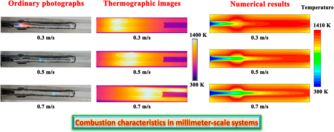
The management of internal features of a cavity structure for channels offers the possibility of inherently effective operation within the flammable limits of a combustible fluid stream while preserving high stability for the flame. However, the precise mechanism by which the cavity method generally provides increased flame stability for millimeter-scale systems remains unclear. The combustion characteristics of methane-air mixtures in millimeter-scale systems with a cavity structure were investigated experimentally and numerically to gain a greater understanding of the mechanisms of flame stabilization and to gain new insights into the characteristics of combustion within spaces with extremely small dimensions. The quenching distance was determined both experimentally and numerically. Stable temperature profiles were obtained from thermographic measurements using infrared radiation. The measurements were compared with the model predictions. Subsequent model calculations demonstrate the effects of variations in wall thermal conductivity, heat losses, flow velocity, equivalence ratio, and channel dimensions. Design recommendations were made. The experimental and numerical results indicated that the quenching distance is slightly larger than commonly believed. The cavity structure has little effect on the quenching distance, but can improve the efficiency and performance of the systems considerably. The cavity structure can effectively extend flammability limits, with an increase of about 18% in the operating range defined by the equivalence ratio of the mixture. The length scale of the systems plays a vital role in stabilizing the flame. The thermal conductivity of the solid material is vital in determining the efficiency and performance of the systems. The design with anisotropic thermal conductivity has significant performance advantages. The flow velocity of the fluid and the equivalence ratio of the mixture are important factors affecting the efficiency and performance of the systems.
Highlights
• The quenching distance is slightly larger than commonly believed.
• The cavity structure has little effect on the quenching distance.
• The length scale of the systems plays a vital role in stabilizing the flame.
• The design with anisotropic thermal conductivity has great performance advantages.
• Important factors affecting performance are determined for the systems.
Introduction
The trend toward the miniaturization of electromechanical devices and the increased demand for micro-power generation with long-life, low-weight devices have resulted in the development of the field of micro-scale combustion. The concept behind this field is that a miniaturized power-generating system will lead to reduced weight and increased lifetime of an electromechanical device that currently requires batteries for power (Dunn-Rankin et al., 2005; Walther and Ahn, 2011). In addition to the interest in miniaturization, the field is also driven by the potential fabrication of electromechanical devices using micro-system technology or rapid prototyping techniques, with their favorable characteristics for low cost and mass production (Dunn-Rankin et al., 2005; Walther and Ahn, 2011). The field of micro-power generation is still in the feasibility stage. Currently, there is consensus that combustion within a micro-scale space is possible with proper chemical and thermal management (Jiaqiang et al., 2021; Jiaqiang et al., 2022). As the length scale of the devices is reduced, the surface-to-volume ratio increases, which eventually leads to heat loss effects becoming significant at the boundaries or surfaces of the devices (Jiaqiang et al., 2021; Jiaqiang et al., 2022). Significant heat loss effects may become problematic due to flame quenching. Consequently, thermal management becomes essential in order to improve flame stabilization by reducing heat losses.
Flame stabilization is a common problem in combustion systems (Jeong et al., 2017; Grib et al., 2020). A flame will propagate through a fuel-air mixture only when certain conditions prevail. Initially, a minimum percentage of fuel must be present within the fuel-air mixture to make the fuel-air mixture flammable, i.e., the lean flammability limit (Mendiburu et al., 2017; Wang et al., 2021). Similarly, a maximum percentage of fuel must be present within the fuel-air mixture wherein greater than this percentage will prevent burning, i.e., the rich flammability limit (Mendiburu et al., 2017; Wang et al., 2021). The flammability range of a fuel-air mixture is that range of the percentage of fuel within the fuel-air mixture between the lean flammability limit and the rich flammability limit.
One reason that flame stabilization is required in combustion systems is to prevent the flame front from moving upstream from the combustion zone toward the source of fuel, i.e., a flashback (Jeong et al., 2017). During a flashback event, the heat of combustion moves upstream and may damage numerous structures within the fuel and air mixing region of the combustor (Hatem et al., 2018; Zangeneh and Alipoor, 2021). Flashback may occur due to auto-ignition of a fuel-air mixture caused by a residence time of the fuel-air mixture in a region upstream of the combustion zone that exceeds the auto-ignition delay time of that fuel-air mixture at the temperature and pressure of that region.
Flame stabilization also is dependent upon speed of the fuel-air mixture entering the combustion zone where propagation of the flame is desired (Wan and Zhao, 2020a; Choi et al., 2020). A sufficiently low velocity must be retained in the region where the flame is desired in order to sustain the flame. As is known, a region of low velocity in which a flame can be sustained can be achieved by causing recirculation of a portion of the fuel-air mixture already burned thereby providing a source of ignition to the fuel-air mixture entering the combustion zone (El-Asrag and Menon, 2007; Fugger et al., 2020). However, the fuel-air mixture flow pattern, including any recirculation, is critical to achieving flame stability. Improvements in flame stability would be desirable and may be especially advantageous in applications in which reduced emissions are needed (Cam et al., 2017; Pashchenko, 2020). Various attempts have been made to achieve such improvements. More specifically, various methods have been tried either commercially or experimentally (Bychkov and Liberman, 2000) and many different structures have already been designed (Shanbhogue et al., 2009). The typical method includes the use of recirculation regions to provide a continuous ignition source by mixing the hot combustion products with the cold incoming fuel and air mixture. Structural devices have been commonly employed to establish a recirculation region for improving the stability of the flame during ignition and operation, such as swirlers (Yilmaz et al., 2020), bluff bodies (Jeong et al., 2017; Fugger et al., 2020), cavities (Yilmaz et al., 2017), and rearward facing steps (Yilmaz et al., 2017). The challenge, however, is presented with respect to the structure of a flame stabilizer that ensures high combustion performance, including improved flame stability and acceptable emissions (Khateeb et al., 2020; Khateeb et al., 2021) while reducing capital and operating costs. Consequently, it would be desirable to provide a flame stabilizer for a combustion system, specifically including a combustion chamber structure that enables the system to maintain high stability of the flame under certain conditions while reducing the emission of undesirable products of combustion such as nitrogen oxides, carbon monoxide, and partially oxidized hydrocarbons.
In conventional lean-premixed combustion, a swirler would typically be used to inject the fuel-lean mixture into the combustor (Broda et al., 1998; Kim and Santavicca, 2013). When a swirler is used, the flame is anchored because the swirler induces recirculation of hot combustion products within the combustor (Panda et al., 2019; Han et al., 2020). The recirculating, hot combustion products continuously contact and ignite the incoming fuel-air mixture, thus anchoring the flame in the vicinity of the recirculation zone. An additional effect of the swirler is to direct the incoming fuel-air mixture outwards toward the walls of the combustor, thus rapidly diffusing the mixture into the combustor, making effective use of the combustor’s volume (Broda et al., 1998; Kim and Santavicca, 2013). As also is known, adding a swirl component to the flow pattern is beneficial, either axial or radial swirl. The designation of a swirl number for a particular type of swirler is known (Kim and Santavicca, 2013): a swirl number less than around 0.4 indicates a weak swirl and no recirculation is obtained; a swirl number between 0.4 and 0.6 indicates a moderate swirl and no recirculation is obtained but the streamlines diverge; and a swirl number greater than 0.6 indicates a strong swirl and recirculation is obtained.
Another method known for causing recirculation is the placement of a bluff body in the flow path of the fuel-air mixture within the combustion zone (Michaels and Ghoniem, 2018; Morales et al., 2019). A bluff body typically defines a leading edge and a trailing edge, and separation of a mixture passing over the bluff body occurs at the trailing edge of the bluff body thereby forming a wake downstream of the trailing edge. The velocity of the mixture in the wake region is much lower than the velocity of the mixture flowing in the main stream around the bluff body thereby supporting recirculation.
The use of a swirler, a bluff body, or a combination of both to cause recirculation is typical in conventional combustion systems (Tong et al., 2018; Gatti et al., 2019). In a micro-combustion system, however, the use of a swirler is undesirable since all fuel and air would typically be premixed upstream of the combustion system and the combustion reaction takes place in the system with typical lateral dimensions below 1 mm (Ju and Maruta, 2011; Kaisare and Vlachos, 2012). On the other hand, one problem associated with using a bluff body as a flame holder for a micro-combustion system is that the flame is anchored to the flame holder and the excessive heat is life-limiting.
One solution that does not require a swirler or a bluff body is the use of cavities. This approach will become increasingly attractive. A number of different suggestions have been made for facilitating a cavity structure in a micro-combustion system (Wan et al., 2015; Fan et al., 2018; Linhong Li et al., 2019; Zhang et al., 2020a; Zhang et al., 2020b; Xu et al., 2021). The inside surface of a micro-combustion system has a plurality of cavities which are spaced apart from one another. Strong combustion can be initiated in the cavities, and the cavity structure can provide for a more compact primary reaction region and for stable flame holding (Wan et al., 2015; Fan et al., 2018). The cavity structure can also cause an increase in residence time for a portion of the mixture, thereby avoiding instability of the flame. Additionally, the utilization of cavities can initiate recirculation of the fuel and air mixture while promoting micro-scale vortex breakdown and enhancing heat and mass transfer (Wan et al., 2015; Fan et al., 2018; Linhong Li et al., 2019; Zhang et al., 2020a; Zhang et al., 2020b; Xu et al., 2021), therefore making the combustion process more stable. More particularly, this method generally comprises a plurality of cavities arranged on the inside surface of a micro-combustion system, thereby providing increased flame stability for the downstream combustion of the premixed fuel and air stream. A further feature provided by the cavity structure is that hot gas and chemically active species can be more easily transferred into the unreacted inlet gas stream for improved performance. More specifically, the free radicals and heat produced by the reaction process can be transported back upstream in the recirculation region to mix with and initiate combustion of the un-reacted fuel and air mixture. The design, however, is quite complex, and the optimization may account for a plurality of factors including the thermal conductivity of the wall material (Wan et al., 2015), the chemically inert gaseous species (Fan et al., 2018), the shape and configuration of the cavity (Linhong Li et al., 2019), the channel structure of the system (Zhang et al., 2020a), and the synergistic effect of cavities and bluff bodies (Zhang et al., 2020b; Xu et al., 2021). For instance, high thermal conductivity materials confer advantage in terms of improved heat transfer properties, but the cavity structure does not necessarily offer unique performance advantages (Wan et al., 2015). The shape and configuration of the cavities are critical to the function and effectiveness of the structure (Linhong Li et al., 2019). The performance of the system may be largely determined by the structure of the channel, such as an axisymmetric bluff body situated closely behind or in front of a cavity (Zhang et al., 2020a; Xu et al., 2021). For example, the hydrodynamics of the system may be significantly altered by the coupling of cavities with bluff bodies (Zhang et al., 2020a), and bluff bodies can beneficially affect the hydrodynamics involving cavities for use in association with the system (Zhang et al., 2020a; Xu et al., 2021), resulting in significantly greater stability of the flame.
Flame stabilization criteria are even more important when the system operates under small-scale conditions (Wan and Zhao, 2020b; Yakovenko and Kiverin, 2021). It would be especially desirable for combustion systems operating under such conditions to have flame stabilizers that would be highly resistant to external flow field dynamics and perturbations. Under small-scale conditions, efficient methods have been developed for reducing combustion instability, such as a spiral heat exchanger structure (Fan et al., 2017), a counter-flow heat exchanger structure (Zuo et al., 2018; Yan et al., 2019), oxygen enriched air (Qingqing Li et al., 2019), a porous medium for use in thermal recirculation (Yilmaz, 2019), a flame holder design (Wan and Zhao, 2020c), and especially a cavity structure (Wan et al., 2015; Fan et al., 2018). Cavities present unique advantages of the improvement in flame stability. The cavity structure may be advantageously employed for the purpose of miniaturization. More specifically, this approach is particularly advantageous for promoting a stable flame in a micro-combustion system (Ju and Maruta, 2011; Kaisare and Vlachos, 2012). Such a cavity can obstruct a flow path to create a recirculation zone for flame stability (Wan et al., 2015; Fan et al., 2018). This in turn causes an increase in residence time for a portion of the fuel-air mixture. A cavity of a particular configuration provides flame holding and initiates recirculation of the fuel and air mixture in a downstream combustion zone, thereby avoiding any issue from flame stability events as much as possible previously described in the literature (Fan et al., 2017; Zuo et al., 2018; Qingqing Li et al., 2019; Yan et al., 2019; Yilmaz, 2019; Wan and Zhao, 2020c), such as flame quenching (Qingqing Li et al., 2019; Yan et al., 2019) and blowout (Fan et al., 2017; Qingqing Li et al., 2019; Yan et al., 2019; Wan and Zhao, 2020c). In this manner, it is possible to maintain the stability of the flame in a micro-combustion system at a higher level than otherwise obtainable, and to obtain higher performance in operation.
Despite extensive efforts over many years, there remains a need for combustion methods that have high performance and stability at various conditions of operations in millimeter-scale systems with a cavity structure. It is essential to maintain combustion characteristics in such a manner that facilitates flame holding in a reliable manner, and minimizes heat loss while maximizing system efficiency. The flame could optimally be as robust as possible in an effort to maximize the efficiency and performance of the systems (Gupta et al., 2020; Abdallah et al., 2021). A fundamental understanding of the stabilization mechanisms of a flame within very small spaces by the cavity method is of both fundamental and practical significance. However, the precise mechanism by which the cavity method generally provides increased flame stability for millimeter-scale systems remains unclear and warrants further study. While high stability of the flames within the systems is desirable, the efficiency and performance can depend on such factors as the overall design of the system, and the potential role of cavity structure in the stabilization mechanism of the flames is poorly understood.
This study relates to the essential characteristics of combustion in millimeter-scale systems with a cavity structure. The quenching distance was determined both experimentally and numerically, and stable temperature profiles were obtained from thermographic measurements. A computational fluid dynamics model was developed to describe the reactive flow. The model combined a detailed chemical kinetic reaction mechanism and a steady treatment of the fluid mechanics. Numerical simulations were conducted to gain insights into system performance such as flames, temperatures, species concentrations, and reaction rates. Methods of applying a cavity structure to channel walls were developed, which may be utilized with presently existing designs of micro-combustion systems. The factors affecting flame stability and combustion characteristics are determined for the systems. The objective of this study is to investigate the characteristics of combustion in millimeter-scale systems with a cavity structure so as to better understand the stabilization mechanisms of a flame within spaces with extremely small dimensions. Particular focus is placed on determining essential factors for design considerations of millimeter-scale systems with improved flame stability and combustion characteristics, and investigating the potential role of cavity structure in the stabilization mechanism of the flames in order to operate the systems more efficiently.
Experimental Methods
The system configured to combust methane is illustrated schematically in Figure 1. The system comprises two parallel fused-quartz plates that are 50.0 mm in length, 13.0 mm in width, and 3.0 mm in thickness. The thermal conductivity of the plate material is 1.4 W/(m⋅K), since fused-quartz is a form of silica, also known as silicon dioxide. A flow channel is formed between the two parallel plates. The millimeter-scale channel has a minimum dimension of 5.0 mm or less, and a length that is, far greater than the minimum dimension. The channel can have any length unless restricted by design requirements. The spacing distance between the two parallel plates is 3.0 mm, which defines the characteristic length of the system. This value is chosen primarily because the spacing distance is slightly greater than the critical distance between the two parallel plates through which the methane flame will not propagate (Jarosiński, 1983; Jarosinski, 1986). This critical dimension can be defined as the quenching distance. In practice, the quenching distance is dependent on many factors, for example, the thermal characteristics of the surrounding material, the composition of the fuel stream, and the shape of the channel (Jarosiński, 1983; Jarosinski, 1986). The distance between the two parallel plates varies from 2.0 to 5.0 mm in order to accurately determine the quenching distance for the system at the given reference conditions.
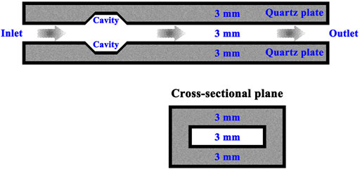
FIGURE 1. Schematic representation of the system comprising two parallel fused-quartz plates with intersecting trapezoidal cavities. The system is configured for operation with methane.
Two trapezoidal cavities are provided in the flow path, as depicted in Figure 1, and the flow is subjected to a sudden expansion in the flow channel to induce disturbances in the flow. The cavities are 1.5 mm in height, 4.0 mm in short base length, and 7.0 mm in long base length, with a distance of 10.0 mm from the flow inlet. In addition, the cavities are designed with an angle of 135° relative to the localized horizontal plates at the points of intersection. The cavities have a rectangular cross-section at any selected station along the flow path, and can be adjusted in position with respect to the flow inlet. In order for flame holding to occur, methane and air must be premixed and provided a low velocity region to reside. Therefore, a low flow velocity of the fluid is used at the flow inlet. In most cases, the flow velocity of the fluid is 0.3 m/s at the flow inlet. A premixed methane-air mixture is fed to the system with a temperature of 300 K. Methane and air are perfectly premixed before they enter the system prior to combustion. The system is designed in stoichiometric operation, because an equivalence ratio of unity is the most reactive mixture composition. Experimental data are therefore obtained based on an initial temperature of 300 K and an equivalence ratio of unity. An ordinary camera is used to form an image using visible light. A thermographic camera is used to create an image using infrared radiation, similar to the ordinary camera that forms an image using visible light. Both emissivity and reflected temperature are adjusted in the thermographic camera to achieve the most accurate thermal image and to determine the corrected temperature. To obtain optimum thermal images, the emissivity of the material surface must be adjusted on the thermographic camera. Correct emissivity adjustment is especially important since the difference in temperature between the measurement environment and the measured object is large. The thermographic camera is precisely calibrated to ensure that the captured pixel values properly correlate to temperatures of the imaged scene. Calibration is performed under controlled conditions with a large number of blackbody reference sources. The thermographic camera is calibrated by the camera manufacturer to factory specifications. Calibration checks are performed by measuring objects with known temperatures and comparing the measured temperatures with the known temperatures. The adjustment to the spacing distance between the two parallel plates is made to determine the flame quenching distance of the system.
The thermographic camera can achieve a resolution of 640 × 480 pixels, and a temperature difference of 1.0 K at the scene induces a maximum temperature difference of 0.02 K at the sensor. The stable fluid centerline temperature profiles are determined from thermographic measurements using infrared radiation, and the thermographic camera is structured to capture and transmit infrared images of the region of interest and to collect temperature data. The fluid centerline temperature measurement is performed in a direction perpendicular to the direction of the flow of the fluid by the thermographic camera from the sides of the system. The method allows the infrared radiation along the fluid centerline to pass through and be received by the thermographic camera, thereby enabling the fluid centerline temperatures to be measured. To precisely measure the distribution of temperature, the emissivity of each material must be determined accurately. However, it is extremely difficult to determine the emissivity of the flame in the system. The total emissivity of the flame is composed of 2.7, 4.3, and 15.0 μm wavelength bands. The emissivity of the flame is predicted using the Schmidt’s theory for the outer region of a flame sheet in thermal equilibrium, followed by an iteration scheme with a wide-band model theory (Schmidt, 1909). More specifically, the empirical correlations suggested by Char and Yeh (1996) are used to predict the cross-section emissivity of the flame by performing a statistical analysis with a dimensionless position parameter. Additionally, both optically thick and optically thin theories are used to make more accurate predictions.
The experiments must be repeated in order to produce data that has acceptable error levels. It is important that the experiments should be repeatable, which is of great importance to the reliability of the experiments and the conclusions supported by the experiments. Experiments are conducted at different times under the same operating conditions, and the number of repetitions of the experiments performed varies from two to six times, depending on the operating conditions applied to the experiments. Such experiments yield almost the same results, which means that the results almost do not change in different trials under the exact same conditions. For example, there is almost no change in temperature while performing the multiple independently-repeated experiments under identical conditions. More specifically, the maximum difference in temperature between different experiments is less than 20 K when the system operates under the same conditions. Error bars can be valuable for understanding the results presented in this study, but they are not shown herein for simplification due to the insignificant difference between the measurement data under the exact same conditions.
Experimental Results and Discussion
Effect of Flow Velocity
The thermographic images acquired in the infrared spectral region are presented in Figure 2A for different flow velocities at the flow inlet, wherein the optical images in the visible spectral region are also presented, thereby allowing for comparisons between different flow velocities in a more intuitive manner. The system is designed in stoichiometric operation. The flow velocity of the fluid varies from 0.3 to 0.7 m/s at the flow inlet. The flow velocity plays a significant role in determining the location of the flame in the system. As the flow velocity increases, the location of the flame moves downstream due to the reduced mean residence time. This means that the location of the flame is very sensitive to changes in the flow velocity, and the flame has a tendency to move downstream when the flow velocity is high, as presented in Figure 2A. Additionally, the rate of heat generation within the system increases with increasing the flow velocity. As a result of the competition between the reduced mean residence time and the increased heat generation rate with increasing the flow velocity, the location of the flame shifts downstream within the system. The stable fluid centerline temperature profiles determined from thermographic measurements using infrared radiation are shown in Figure 2B. As the flow velocity increases, the location of the peak temperature moves downstream significantly, which shows good agreement with the results obtained for the location of the flame. However, because the location of the flame is determined by the flow velocity being utilized, the system must be specifically configured or designed for use within a particular range of flow velocity. This imposes significant limits on the flow velocities that can be employed.
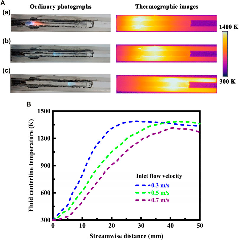
FIGURE 2. (A) Optical and thermographic images showing laminar premixed methane flames and temperature variation in the system under different flow velocity conditions. The flow velocity of the fluid at the flow inlet is given as follows: (a) 0.3 m/s, (b) 0.5 m/s, and (c) 0.7 m/s. A thermographic camera is used to detect infrared radiation in a way similar to the way an ordinary camera detects visible light. The system is designed in stoichiometric operation; (B) Stable fluid centerline temperature profiles determined from thermographic measurements using infrared radiation. The system is designed in stoichiometric operation.
To understand how to design the system with improved flame stability, it is necessary to determine the quenching distance for the system. The quenching distance varies with mixture composition, thermodynamic conditions, and channel wall characteristics (Jarosiński, 1983; Jarosinski, 1986). The spacing distance between the two parallel plates varies from 2.0 to 5.0 mm to determine the quenching distance. The measurement results indicate that the flame is stable when the spacing distance between the two parallel plates is larger than 2.5 mm, and combustion cannot be sustained when the spacing distance is less than 2.5 mm. Based on this flame stability criteria, the critical value for the quenching distance takes 2.5 mm, which is the minimum allowable distance that ensures flame propagation at the specified composition and thermodynamic conditions. It has been commonly believed that the quenching distance of the methane flame varies from 2.0 to 2.5 mm under stoichiometric conditions, depending on the cavity structure and dimensions. The use of cavities may provide improved flame stability for the downstream combustion of the stream (Wan et al., 2015; Fan et al., 2018; Linhong Li et al., 2019; Zhang et al., 2020a; Zhang et al., 2020b; Xu et al., 2021). However, the quenching distance determined for the system is almost identical to that determined for a smooth system designed without cavities. Therefore, the cavity structure has little effect on the quenching distance.
Effect of Equivalence Ratio
The thermographic images acquired in the infrared spectral region, and the optical images in the visible spectral region, are presented in Figure 3A for different equivalence ratios of the mixture at the flow inlet. The stable exterior wall temperature profiles determined from thermographic measurements using infrared radiation are shown in Figure 3B. The flow velocity of the fluid is 0.3 m/s at the flow inlet. The equivalence ratio of the mixture varies from 0.4 to 1.2 at the flow inlet.
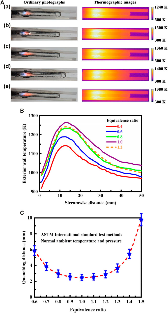
FIGURE 3. (A) Optical and thermographic images showing laminar premixed methane flames and temperature variation in the system under different equivalent ratio conditions. The equivalent ratio of the mixture at the flow inlet is given as follows: (a) 0.4, (b) 0.6, (c) 0.8, (d) 1.0, and (e) 1.2. The flow velocity of the fluid is 0.3 m/s at the flow inlet; (B) Stable exterior wall temperature profiles determined from thermographic measurements using infrared radiation. The flow velocity of the fluid is 0.3 m/s at the flow inlet; (C) Effect of equivalence ratio on the quenching distance of the methane flame at normal ambient temperature and pressure. The quenching distance of the methane flame is determined experimentally as described in the ASTM International standard test methods (ASTM International, 2016; ASTM International, 2021).
In all the cases, the mixture is ultimately raised to a temperature at which the combustion reaction occurs in the entire gas stream, as presented in Figure 3A. Strong combustion is initiated in the cavities. The cavity structure provides for a more compact primary reaction region and for stable flame holding that is, especially desirable over an extended operating range. This is principally because the structural arrangement increases the intensity of combustion through enhanced heat and mass transfer (Wan et al., 2015; Fan et al., 2018), making the combustion process more stable. A further feature provided by the cavity structure is that some combustion products, such as hot gas and chemically active species, in the primary reaction region are more easily transferred into the unreacted inlet gas stream for improved performance. As a result, the structural arrangement creates small recirculation regions for additional mixing of the hot and chemically reactive combustion products into the incoming channel flow, thereby improving the stability of the flame. Consequently, the utilization of cavities can initiate recirculation of the fuel and air mixture, thereby enhancing heat and mass transfer and providing increased flame stability for the downstream combustion of the premixed fuel and air stream.
The system fueled by methane is capable of operating over a large range of equivalence ratios, such as operation with the mixture that is, as lean as two fifths of stoichiometric fuel, as presented in Figure 3A. At the lowest equivalence ratio, the flame is less intense, and the large amount of excess air reduces the peak flame temperature, thus causing a reduction of thermal efficiency. All the mixtures will burn if the fuel concentration lies within the equivalence ratio range. However, the maximum temperature is reached for a stoichiometric mixture, as shown in Figure 3B. The peak temperature is decreased as the mixture is made fuel-richer or fuel-leaner. The flame is anchored to the duct between the two cavities in all the cases. Consequently, the equivalence ratio has little effect on the location of the flame in the system. In the operation of the system, a back-flow region will be initiated by the cavities due to a sudden change of cross section (Wan et al., 2015; Fan et al., 2018; Linhong Li et al., 2019; Zhang et al., 2020a; Zhang et al., 2020b; Xu et al., 2021), which serves to stabilize the flame for the system. One problem associated with using cavities as a flame holder for the system is that the excessive heat may be life-limiting. Operation will not make the mixture flammable when the mixture is as lean as one fifth of stoichiometric fuel, and therefore the equivalence ratio in this case is less than the lean flammability limit.
The fuel-air mixture will burn only if the concentration of the fuel lies within well-defined lower and upper bounds determined experimentally, referred to as flammability limits. The measurement of flammability limits is performed in order to appropriately design the system and to gain a fundamental understanding of flammability properties of the mixture. However, the characterization of the flammability envelope of the mixture is time consuming and quite difficult through experimental tests. The experimental results indicate that there is a range of methane to air equivalence ratios within which combustion can occur or be sustained within the millimeter-scale systems. The lean and rich flammability limits expressed in terms of the equivalence ratio of the mixture, which define the stable combustion operating range, are 0.38 and 2.2 for the system designed without cavities, and 0.32 and 2.6 for the system designed with cavities. The cavity structure can effectively extend the flammability limits of the mixture, with an increase of about 18% in the operating range defined by the equivalence ratio of the mixture. Consequently, the cavity structure will lead to a wider operating range in terms of the lean and rich flammability limits, with improved flame stability.
The effect of equivalence ratio on the quenching distance of the methane flame is investigated at normal ambient temperature and pressure in order to offer the possibility of inherently safe operation within the flammability limits of the mixture. The results are presented in Figure 3C, in which the quenching distance of the methane flame is plotted against the equivalence ratio of the fuel to air. Since the quenching distance of the methane flame depends on a number of factors, such as gas composition, thermodynamic conditions, and channel wall characteristics, it is determined experimentally as described in the ASTM International standard test methods (ASTM International, 2016; ASTM International, 2021). The quenching distance is the minimum spacing distance that permits sustained propagation of the methane flame at the specified temperature and pressure conditions. The quenching distance depends heavily on the equivalence ratio of the fuel to air over the entire range of variation, as shown in Figure 3C. Additionally, the quenching distance increases with increasing deviation from stoichiometry. Below the quenching distance, ignition of the mixture will not develop into a methane flame. As the spacing distance increases beyond the quenching distance, propagation of the methane flame is possible within the flammability limits.
Numerical Model
Description of the System
The system is modeled as two parallel plates and two cavities with dimensions described in detail above. The spacing distance between the two parallel plates is 3.0 mm, unless the context dictates otherwise. To model the combustion reaction of the mixture, the system is simplified as a two-dimensional problem due to the high aspect ratio of the system. It is worth noting that the aspect ratio is the ratio of the height to the width of the channel, and the height is the spacing distance between the two parallel plates. However, to improve the realism of the model and to resolve the combustion problem with greater accuracy (Maruta, 2011; Pashchenko, 2017), further study is needed to perform computational fluid dynamics simulations in three dimensions.
Mathematical Model
The model is implemented in FLUENT (ANSYS, 2018), available from ANSYS Inc., Release 19.2, to obtain the steady-state solution for the reacting flow problem. FLUENT permits modeling of reacting flow (Wang and Fan, 2021) and related transport phenomena (Yang et al., 2019; Yilmaz, 2019) in the combustion process, and various modes of heat transfer can be modeled (Peng et al., 2019; Zhao and Fan, 2020). The continuity equation is given by
where ρ is the density, ux is the axial velocity, and uy is the transverse velocity.
The axial and transverse momentum conservation equations are given by
wherein μ is the dynamic viscosity, and p is the pressure.
The energy conservation equation can be written as follows:
wherein h is the enthalpy, w is the mass fraction, k is the thermal conductivity, V is the diffusion velocity, T is the absolute temperature, and K is the total number of chemical species present in the system. Species k is denoted by the subscript k, and the gas mixture is denoted by the subscript g.
For the combustion reaction occurring in the bulk gas phase, the species transport equation can be written as follows:
in which
The diffusion velocity of gaseous species k arises because of gradients of both temperature and concentration, which can be computed as follows:
wherein
The pressure is represented by the kinetic theory of gases:
where R is the ideal gas constant.
For heat conduction in the solid region, the energy conservation equation is given by
The solid material is denoted by the subscript s.
At the gas-solid phase boundaries, the energy conservation equation is given by
wherein
The equation for exterior heat losses is given by
in which ho is the exterior heat loss coefficient, ε is the emissivity factor,
Numerical Methods
The combustion process is modeled with GRI-MECH 3.0 (Smith et al., 2000), and the detailed mechanism is invariably stiff (Westbrook et al., 2005). The typical meshes used in computational fluid dynamics simulations are illustrated in Figure 4A for the system designed without cavities and for the system designed with cavities. More nodes are accumulated around the reaction regions and around the cavity structure. In total, the typical mesh consists of 28,000 nodes for the system designed without cavities and 32,000 nodes for the system designed with cavities. A mesh independence test is performed to assure independence of the solution to the combustion problem. The stable temperature profiles along the fluid centerline of the system designed with cavities are presented in Figure 4B for meshes with different nodal densities. As the mesh density increases, there is a convergence of the solution. Solutions obtained with a mesh consisting of 32,000 nodes are reasonably accurate. Larger mesh densities, up to 64,000 nodes, offer no obvious advantage. The specific heat of the mixture is defined as a function of composition, and the specific heat of each species is defined as a piecewise-polynomial function of temperature. The solution to the problem is deemed to have converged when the residual is less than 10−6 for each of the conservation equations described above.
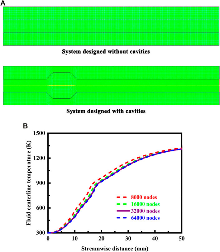
FIGURE 4. (A) Typical meshes used in computational fluid dynamics simulations for the system designed without cavities and for the system designed with cavities. More nodes are placed around the reaction regions and around the cavity structure; (B) Stable fluid centerline temperature profiles for meshes with different nodal densities. The stable temperature profiles are presented along the fluid centerline of the system designed with cavities. Additionally, the flow velocity of the fluid is 0.7 m/s at the flow inlet, and the system is designed in stoichiometric operation.
Validation of the Model
The temperature profiles along the fluid centerline under different flow velocity conditions are presented in Figure 5. The temperature profiles are determined from thermographic measurements using infrared radiation and predicted by the model. The system is designed in stoichiometric operation. The model is in reasonable agreement with the experimental measurements.
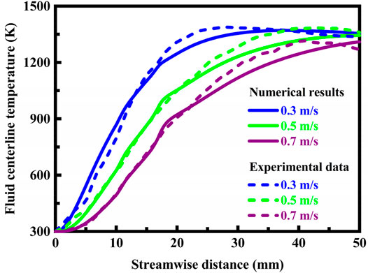
FIGURE 5. Stable fluid centerline temperature profiles determined from thermographic measurements using infrared radiation and predicted by the model using computational fluid dynamics. The system is designed in stoichiometric operation.
Numerical Results and Discussion
Effect of Cavities
The contour plots of temperature in the system are presented in Figure 6A in different geometrical configurations. Accordingly, the temperature profiles along the fluid centerline and on the exterior walls are presented in Figure 6B for the system designed in different geometrical configurations, and the methane concentration profiles along the fluid centerline are presented in Figure 6C. The system is designed in stoichiometric operation. The thermal conductivity of the solid material is 1.4 W/(m⋅K), which is in consistence with that of the fused-quartz used in the experiments.
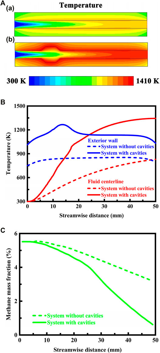
FIGURE 6. (A) Contour plots of temperature in the system designed in different geometrical configurations. The system is configured (a) without cavities and (b) with cavities. The system is designed in stoichiometric operation, the exterior heat loss coefficient is 20 W/(m2⋅K), and the flow velocity of the fluid is 0.3 m/s at the flow inlet. The thermal conductivity of the solid material is 1.4 W/(m⋅K), which is in consistence with that of the fused-quartz used in the experiments; (B) Temperature profiles along the fluid centerline and on the exterior walls of the system designed in different geometrical configurations. The system is designed in stoichiometric operation, the exterior heat loss coefficient is 20 W/(m2⋅K), the flow velocity of the fluid is 0.3 m/s at the flow inlet, and the thermal conductivity of the solid material is 1.4 W/(m⋅K); (C) Methane concentration profiles along the fluid centerline of the system designed in different geometrical configurations. The system is designed in stoichiometric operation, the exterior heat loss coefficient is 20 W/(m2⋅K), the flow velocity of the fluid is 0.3 m/s at the flow inlet, and the thermal conductivity of the solid material is 1.4 W/(m⋅K).
There is a sharp rise in temperature caused by the combustion process, which is significantly affected by the geometrical configuration of the system. Specifically, the temperature in the system designed with cavities is much higher than that in the system designed without cavities, as illustrated in Figure 6A and shown in Figure 6B. The cavities result in a sudden expansion in the flow domain. This sudden expansion of cross section could potentially promote ignition by the flame front propagating through the cavities immediately to upstream of the expansion. Additionally, the sudden expansion of cross section may induce disturbances in the flow region (Pan et al., 2019; Huang et al., 2020) and the cavitated surfaces provide an increased total heat transfer surface area in the region, thereby enhancing heat transfer between the fluid and the solid material and subsequently to the upstream structure of the system by heat conduction through the channel walls. As a result of this combination, the predicted temperature in the system designed with cavities becomes much higher than that in the system designed without cavities. This sharp rise in temperature can raise the flame front speed and therefore may lower the extinction limit temperature and could improve the stability of the flame.
The absence of cavities can lead to sub-optimum combustion. This in turn can be related to, for example, incomplete combustion resulting in poor efficiency, as shown in Figure 6C. In contrast, the intensity and efficiency of combustion are enhanced through the use of the cavity structure for the system. More specifically, the system designed with cavities has the advantage of substantially complete conversion of methane at the flow outlet, as shown in Figure 6C. The intense combustion activity serves as a mechanism to facilitate the interaction between the hot combustion products and the cold incoming fuel and air mixture, thereby improving the stability of the flame. The importance of enhancing this interaction has been clearly demonstrated in the literature (Wan et al., 2015; Fan et al., 2018). As a result, the cavities can be configured to provide flame holding and initiate recirculation of the fuel and air mixture in a downstream combustion region. This in turn causes an increase in residence time for a portion of the fuel-air mixture, thereby avoiding instability of the flame. The combustion is stabilized because the free radicals and heat produced by the reaction process are transported back upstream in the recirculation region to mix with and initiate combustion of the un-reacted fuel and air mixture. Stable combustion is therefore heavily dependent on the recirculation of the hot and chemically active combustion products back upstream. When the velocity of the recirculated combustion products is increased, the flux of combustion products upstream increases and the combustion process tends to become more stable over a wider range of operating conditions. However, flame holding may cause serious damage to the system, since the increased temperature within the cavities would exceed the design temperature of the wall material.
The use of cavities fundamentally changes the stability of the flame, as discussed above. The efficiency and performance of this system can be further improved, since the number and position of the cavities can vary depending upon the specific application and the fluid used. Additionally, the shape of the cavities can be adapted to further improve the recirculation of the hot and chemically active combustion products and the stability of the flame. Consequently, further optimization steps are required to fully exploit the benefits of the cavity structure while providing efficient and stable combustion. In this manner, it is possible to maintain the stability of the flame within the system at a higher level than otherwise obtainable, and to obtain higher performance in operation.
Effect of Wall Thermal Conductivity
The millimeter-scale system with a cavity structure is designed in stoichiometric operation. In order for flame holding to occur, methane and air must be premixed and provided a low velocity region to reside. Therefore, a low flow velocity profile is specified at the flow inlet. The contour plots of temperature and methane concentration in the system are presented in Figures 7A,B, respectively, under different thermal conductivity conditions. Accordingly, the temperature profiles along the fluid centerline and on the exterior walls are presented in Figures 8A,B, respectively, under different thermal conductivity conditions.
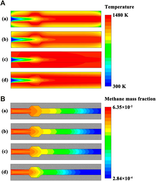
FIGURE 7. (A) Contour plots of temperature in the system under different thermal conductivity conditions. The thermal conductivity of the solid material is defined as follows: (a) 0.5 W/(m⋅K), (b) 1.4 W/(m⋅K), (c) 50 W/(m⋅K), and (d) 50 W/(m⋅K) in the longitudinal direction and 0.5 W/(m⋅K) in the transverse direction. The system is designed in stoichiometric operation, the exterior heat loss coefficient is 20 W/(m2⋅K), and the flow velocity of the fluid is 0.3 m/s at the flow inlet; (B) Contour plots of methane concentration in the system under different thermal conductivity conditions. The thermal conductivity of the solid material is defined as follows: (a) 0.5 W/(m⋅K), (b) 1.4 W/(m⋅K), (c) 50 W/(m⋅K), and (d) 50 W/(m⋅K) in the longitudinal direction and 0.5 W/(m⋅K) in the transverse direction. The system is designed in stoichiometric operation, the exterior heat loss coefficient is 20 W/(m2⋅K), and the flow velocity of the fluid is 0.3 m/s at the flow inlet.
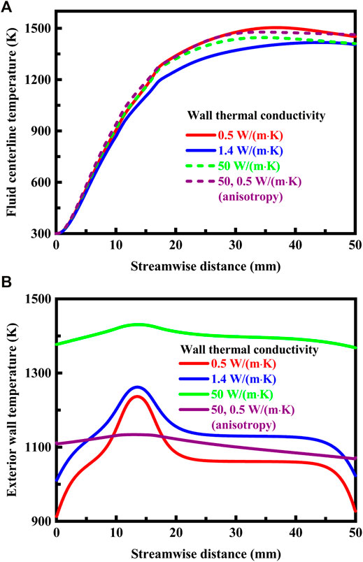
FIGURE 8. (A) Temperature profiles along the fluid centerline under different thermal conductivity conditions. For the anisotropic solid material, the thermal conductivity is 50 W/(m⋅K) in the longitudinal direction and 0.5 W/(m⋅K) in the transverse direction. The system is designed in stoichiometric operation, the exterior heat loss coefficient is 20 W/(m2⋅K), and the flow velocity of the fluid is 0.3 m/s at the flow inlet; (B) Temperature profiles on the exterior walls under different thermal conductivity conditions. For the anisotropic solid material, the thermal conductivity is 50 W/(m⋅K) in the longitudinal direction and 0.5 W/(m⋅K) in the transverse direction. The system is designed in stoichiometric operation, the exterior heat loss coefficient is 20 W/(m2⋅K), and the flow velocity of the fluid is 0.3 m/s at the flow inlet.
The thermal conductivity of the solid material has little effect on temperature of the fluid, as shown in Figures 7A, 8A. This in turn can be related to small differences in methane concentration and conversion, and efficient combustion occurs with the mixture in all the cases, as shown in Figure 7B. In contrast, the thermal conductivity of the solid material has a significant effect on the temperature of the channel walls, as shown in Figures 7A, 8B. The wall temperature profile depends heavily upon the thermal conductivity of the solid material. The temperature gradient is steep within the channel walls with a low thermal conductivity. The temperature of the exterior walls typically increases with increase in the thermal conductivity of the solid material, as shown in Figure 8B. An important feature of the solid material is that high enough operating temperatures are achievable in the combustion process to permit effective use of the fuel, as shown in Figure 7B. A portion of heat of reaction is transferred to the upstream structure of the system by heat conduction through the channel walls and by radiation through the bulk gas phase. This is necessary for ignition and flame stability (Norton and Vlachos, 2003; Norton and Vlachos, 2004). The solid material is advantageously thermally conductive to permit a high wall temperature with more uniform distribution, as shown in Figures 7A, 8B. Higher thermal conductivity levels would be advantageous to the system. For the solid material with a very low thermal conductivity, it is possible to achieve essentially adiabatic combustion in the system. If the thermal conductivity is low enough for the solid material, the maximum temperature might even approach the theoretical adiabatic flame temperature under the specified operation conditions.
The term anisotropy indicated in Figures 8A,B is used to describe direction-dependent thermal conductivity of the solid material, and assumes different thermal conductivities in different directions. In this case, the solid material conducts heat in a way that is, anisotropic. For example, the materials used to transfer and reject heat from the heat source in electronics are often anisotropic (Tian et al., 2013; Kang et al., 2018). When the solid material has anisotropic thermal conductivity, heat conduction is anisotropic within the channel walls, as illustrated in Figure 7A. Despite the short length of the channel, heat losses to the surroundings may be substantial, but can be reduced by the anisotropic solid material. More specifically, the anisotropic solid material inhibits transverse but allows longitudinal heat conduction, as illustrated in Figure 7A. The channel walls permit heat flux in the longitudinal direction to preheat the fluid, yet does not permit heat losses in the transverse direction to the surroundings, which can be accomplished by using anisotropic composite materials (Wan et al., 2017; Wang et al., 2019) or forming vacuum chambers within the channel walls.
Effect of Heat Losses
In practical operation of the system, there may occur considerable heat losses to the environment, resulting in damage to the stability of the flame, and unsatisfactory operation (Fernandez-Pello, 2002; Wan and Fan, 2021). Heat losses from the channel walls may be significant due to the high aspect ratio of the system (Sakurai et al., 2009; Wang et al., 2020). Operation of the system with a low heat loss coefficient is desirable in order to reliably avoid excessive heat losses. To better understand the underlying cause for the stability of the flame, the effect of heat losses on the temperature in the system is evaluated. The contour plots of temperature in the system are presented in Figure 9A under different exterior heat loss conditions. Accordingly, the temperature profiles along the fluid centerline and on the exterior walls are presented in Figures 9B,C, respectively, under different exterior heat loss conditions.
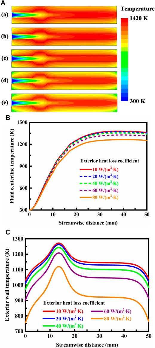
FIGURE 9. (A) Contour plots of temperature in the system under different exterior heat loss conditions. The exterior heat loss conditions are specified with the exterior heat loss coefficient as follows: (a) 10 W/(m2⋅K), (b) 20 W/(m2⋅K), (c) 40 W/(m2⋅K), (d) 60 W/(m2⋅K), and (e) 80 W/(m2⋅K). The system is designed in stoichiometric operation, the thermal conductivity is 1.4 W/(m⋅K) for the solid material, and the flow velocity of the fluid is 0.3 m/s at the flow inlet; (B) Temperature profiles along the fluid centerline under different exterior heat loss coefficient conditions. The system is designed in stoichiometric operation, the thermal conductivity is 1.4 W/(m⋅K) for the solid material, and the flow velocity of the fluid is 0.3 m/s at the flow inlet; (C) Temperature profiles on the exterior walls under different exterior heat loss coefficient conditions. The system is designed in stoichiometric operation, the thermal conductivity is 1.4 W/(m⋅K) for the solid material, and the flow velocity of the fluid is 0.3 m/s at the flow inlet.
An increase of the exterior heat loss coefficient leads to a decrease of the temperature in the system, as illustrated in Figure 9A and shown in Figures 9B,C. As the exterior heat loss coefficient increases, the exterior heat losses are enhanced through the undesirable heat conducting paths. These heat losses result in a drop in the temperature in the system. The change in temperature becomes significant at high exterior heat loss coefficients. The underlying cause is due to the high aspect ratio of the system. When the exterior heat loss coefficient is high, a considerable amount of heat supplied by combustion is dissipated to the surroundings, which could eventually lead to unsatisfactory operation or even failure. At sufficiently high heat-loss conditions, the temperature of the flame becomes sufficiently low that the rate of heat losses to the surroundings exceeds the release rate of combustion heat and the flame can no longer sustain itself within the system. This condition is referred to as the extinction limit of the flame and provides a higher boundary for the exterior heat loss coefficient. The critical exterior heat loss coefficient at which the flame cannot propagate within the system is dependent on several factors, such as the equivalence ratio of the mixture, the thermal conductivity of the solid material, and the flow velocity of the fluid. When a set of specified values are assumed for these factors, the critical exterior heat loss coefficient can be accurately determined. For example, the critical exterior heat loss coefficient is 97 W/(m2⋅K) for the system, when the system is designed in stoichiometric operation, the thermal conductivity is 1.4 W/(m⋅K) for the solid material, and the flow velocity of the fluid is 0.3 m/s at the flow inlet. The system usually operates dangerously near to the extinction limit. However, the disadvantage associated with the significant heat losses from the system can be fully avoided by the use of a solid material that has anisotropic thermal conductivity. For example, undesirable heat losses are effectively reduced by reducing the transverse thermal conductivity but increasing the longitudinal thermal conductivity, as discussed above.
The reaction rate profiles along the fluid centerline are presented in Figure 10 under different exterior heat loss conditions. When the exterior heat loss coefficient is low, a desirably high reaction rate level is maintained within the system and the system is capable of dissipating only a small amount of heat. As the exterior heat loss coefficient increases, the rate of the combustion reaction falls rapidly and the occurring heat losses increase significantly. In the present study, the exterior heat loss coefficient can be equal to or less than 80 W/(m2⋅K) without causing the combustion reaction to be quenched, which is higher than that the critical exterior heat loss coefficient determined for a similar system but without cavities (Norton and Vlachos, 2003; Norton and Vlachos, 2004). This is because the utilization of cavities can enhance heat and mass transfer (Wan et al., 2015; Fan et al., 2018; Linhong Li et al., 2019; Zhang et al., 2020a; Zhang et al., 2020b; Xu et al., 2021), thereby providing substantially increased stability for the flame. The system designed with cavities makes possible an operation with very high heat losses, in comparison with that designed without cavities. In the practical design, it is desired to maximize the rate of the combustion reaction without quenching the reaction (Westbrook et al., 1981; Bradley et al., 2020). As the system approaches extinction, the maximum reaction rate decreases, but the reaction region does not shift downstream and is not widely expanded spatially, as shown in Figure 10. Interestingly, the location of the flame also does not move downstream with increasing the exterior heat loss coefficient, as illustrated in Figure 9A. At a sufficiently high exterior heat loss coefficient, the combustion reaction is quenched, but without leaving the system. Unstable combustion conditions resulting from serious heat losses can be substantially reduced or eliminated by using a solid material that has anisotropic thermal conductivity, as discussed above. This advantageously facilitates the use of the solid material.
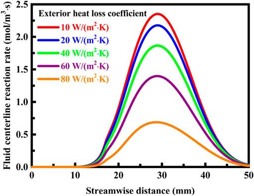
FIGURE 10. Reaction rate profiles along the fluid centerline under different exterior heat loss coefficient conditions. The system is designed in stoichiometric operation, the thermal conductivity is 1.4 W/(m⋅K) for the solid material, and the flow velocity of the fluid is 0.3 m/s at the flow inlet.
Effect of Flow Velocity
Operation conditions in the system are normally dictated by power requirements, which are limited by inlet conditions, such as the flow velocity of the fluid at the flow inlet. The effect of flow velocity is evaluated while maintaining a constant equivalence ratio of the mixture at the flow inlet. The contour plots of temperature and methane concentration in the system are presented in Figures 11A,B, respectively, under different inlet flow velocity conditions. Accordingly, the temperature along the fluid centerline is plotted in Figure 11C against the streamwise distance at different inlet flow velocity conditions.
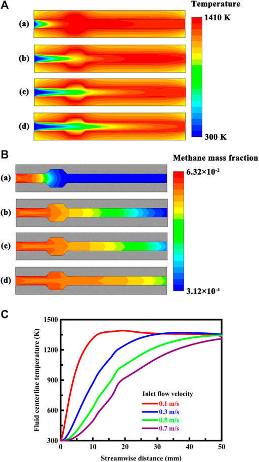
FIGURE 11. (A) Contour plots of temperature in the system under different flow velocity conditions. The flow velocity of the fluid is defined at the flow inlet as follows: (a) 0.1 m/s, (b) 0.3 m/s, (c) 0.5 m/s, and (d) 0.7 m/s. The system is designed in stoichiometric operation, the exterior heat loss coefficient is 20 W/(m2⋅K), and the thermal conductivity is 1.4 W/(m⋅K) for the solid material; (B) Contour plots of methane concentration in the system under different flow velocity conditions. The flow velocity of the fluid is defined at the flow inlet as follows: (a) 0.1 m/s, (b) 0.3 m/s, (c) 0.5 m/s, and (d) 0.7 m/s. The system is designed in stoichiometric operation, the exterior heat loss coefficient is 20 W/(m2⋅K), and the thermal conductivity is 1.4 W/(m⋅K) for the solid material; (C) Temperature profiles along the fluid centerline under different inlet flow velocity conditions. The system is designed in stoichiometric operation, the exterior heat loss coefficient is 20 W/(m2⋅K), and the thermal conductivity is 1.4 W/(m⋅K) for the solid material.
The flow velocity plays a significant role in determining the location of the reaction region in the system. As the flow velocity increases, the location of the flame moves downstream significantly, as illustrated in Figures 11A,B and shown in Figure 11C. The flame is preferentially located as close as possible to the cavities, because vortex breakdown occurs just downstream of the cavities (Krishna and Ravikrishna, 2015; Aravind and Deepu, 2020), thereby enabling flame holding to be achieved in the system. An important metric taken into consideration within the system is the flame which remains stable over a range of flow velocities. At high flow velocities, the flame may blow out of the system, so that no flame exists. The problem of blowout limits the allowable flow velocities in the system. For the system, proper selection of the flow velocity shifts the flame location away from blowout, thereby allowing operation of the system at the desired stable region. The system makes impossible an operation with very high flow velocities, as it usually operates dangerously near to the blowout limit of the flame. Additionally, the front of the flame is widely expanded spatially, as illustrated in Figures 11A,B, and the flame is therefore unstable. Consequently, a high flow velocity is to be avoided in order to ensure a stable operation for the system. Care has to be taken here that the flow velocity of the fluid is not too high, so that the flame does not blow out of the system, which is essential for the function of the system.
The conversion of methane at the flow outlet is plotted in Figure 12A against the flow velocity of the fluid at the flow inlet. High flow velocities can lead to sub-optimum combustion. This in turn can be related to, for example, incomplete combustion resulting in poor efficiency, as shown in Figure 12A. A flow velocity less than 0.5 m/s at the flow inlet ensures good operation performance for the system. Blowout is a particular concern when high flow rates are attempted. The problem of flame blowout has become increasingly severe over a variety of systems (Chang et al., 2020; Wan and Zhao, 2020d), since they are required to achieve better performance and meet severe operability constraints. The reaction rate profiles along the fluid centerline are presented in Figure 12B under different inlet flow velocity conditions. When the flow velocity of the fluid is 0.7 m/s at the flow inlet, the position of the maximum reaction rate approaches closely to the flow outlet, and the flame may blow out of the system. The blowout limit is of major importance in operating the system. At flow velocities higher than 0.7 m/s at the flow inlet, stable combustion cannot be achieved in the system. It is therefore not desirable to operate the system in this regime. The rate of the combustion reaction is plotted in Figure 12C against the streamwise distance at different transverse distances. The reaction rate approaching to the interior walls is much higher than that in the other regions, and the cavities have a positive effect on the rate of the combustion reaction. Interestingly, the cavity structure results in reaction rate fluctuations under the operation conditions. These reaction rate fluctuations may create significant problems for the operation of the system.
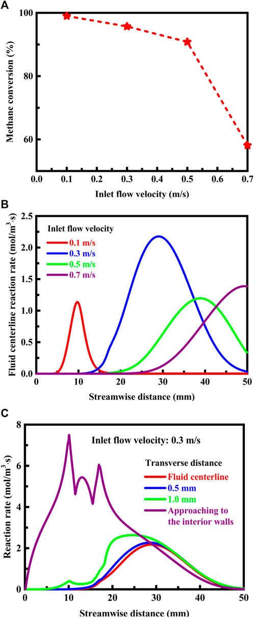
FIGURE 12. (A) Methane conversion at the flow outlet as a function of the flow velocity of the fluid at the flow inlet. The system is designed in stoichiometric operation, the exterior heat loss coefficient is 20 W/(m2⋅K), and the thermal conductivity is 1.4 W/(m⋅K) for the solid material; (B) Reaction rate profiles along the fluid centerline under different inlet flow velocity conditions. The system is designed in stoichiometric operation, the exterior heat loss coefficient is 20 W/(m2⋅K), and the thermal conductivity is 1.4 W/(m⋅K) for the solid material; (C) Reaction rate profiles as a function of the streamwise distance at different transverse distances. The flow velocity of the fluid is 0.3 m/s at the flow inlet. The system is designed in stoichiometric operation, the exterior heat loss coefficient is 20 W/(m2⋅K), and the thermal conductivity is 1.4 W/(m⋅K) for the solid material.
Effect of Equivalence Ratio
The system can be designed for equivalence ratios significantly less or greater than unity. However, the operation of the system is required within the normal limits of flame stability. Methane is therefore present within the fuel-air mixture between the lean flammability limit and the rich flammability limit, and the overall combustion stoichiometry is varied accordingly. The contour plots of temperature in the system are presented in Figure 13A under different equivalence ratio conditions. Accordingly, the temperature profiles along the fluid centerline and on the exterior walls are presented in Figures 13B,C, respectively, under different equivalence ratio conditions.
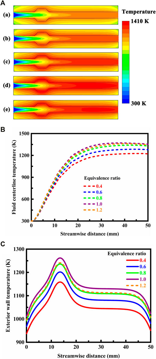
FIGURE 13. (A) Contour plots of temperature in the system under different equivalence ratio conditions. The composition of the mixture is specified with the equivalence ratio as follows: (a) 0.4, (b) 0.6, (c) 0.8, (d) 1.0, and (e) 1.2. The thermal conductivity is 1.4 W/(m⋅K) for the solid material, the exterior heat loss coefficient is 20 W/(m2⋅K), and the flow velocity of the fluid is 0.3 m/s at the flow inlet; (B) Temperature profiles along the fluid centerline under different equivalence ratio conditions. The thermal conductivity is 1.4 W/(m⋅K) for the solid material, the exterior heat loss coefficient is 20 W/(m2⋅K), and the flow velocity of the fluid is 0.3 m/s at the flow inlet; (C) Temperature profiles on the exterior walls under different equivalence ratio conditions. The thermal conductivity is 1.4 W/(m⋅K) for the solid material, the exterior heat loss coefficient is 20 W/(m2⋅K), and the flow velocity of the fluid is 0.3 m/s at the flow inlet.
Combustion cannot occur or be sustained when the equivalence ratio is 0.2, but the fuel is flammable in the system for equivalence ratios greater than or equal to 0.4, as illustrated in Figure 13A. However, methane can be admixed with a larger amount of air so as to maintain the desired flame temperature in the system, for example, equivalence ratios less than or equal to 0.8. In this case, the flame temperature is reduced, and in particular, thermal production of nitrogen oxides is minimal (Miller and Bowman, 1989; Bowman, 1992). At the lower flame temperatures, however, flame stability becomes problematic, as the rate of reaction may be insufficient to prevent localized or global extinction. To increase the temperature, the combustion reaction of methane with air can be enhanced by increasing fuel lean stoichiometry close to the stoichiometric value. More specifically, the temperature increases with increasing the equivalence ratio of the mixture from 0.4 to unity, as shown in Figures 13B,C. A fuel-rich or sub-stoichiometric mixture contains less air than the amount theoretically required for complete combustion, and therefore has an equivalence ratio of greater than unity. Lower temperatures are obtained, when the mixture to be combusted is sub-stoichiometric. However, a fuel-rich mixture will make the use of the system absurd due to the increased noxious emissions (Kennedy et al., 2000; Song et al., 2003). Preferentially, the system is designed in stoichiometric operation, because a significantly higher temperature can be reached. Specifically, the maximum temperature occurs at near stoichiometric conditions, as shown in Figures 13B,C. The amount of air provided can consume all the fuel completely at an equivalence ratio of unity. As the equivalence ratio of the mixture becomes less than or exceeds unity, the maximum temperature decreases. For example, the maximum temperature is decreased by adding excess air. The maximum temperature becomes sufficiently low under sufficiently fuel-lean conditions, for example, at an equivalence ratio of 0.5. In this case, the rate of heat losses to the surroundings exceeds the release rate of combustion heat and the flame can no longer sustain itself within the system. This condition is referred to as the extinction limit of the flame.
Effect of Channel Height
The system is designed in stoichiometric operation, because an equivalence ratio of unity is the most reactive mixture composition. In order for flame holding to occur, a low flow velocity profile is specified at the flow inlet. The effect of channel dimensions is evaluated to ensure the stable operation of the system and to determine the quenching distance. The contour plots of temperature and methane concentration in the system are presented in Figures 14A,B, respectively, under different channel height conditions. The channel height is the spacing distance between the two parallel plates, which is the characteristic length of the system. The channel height varies from 2.0 to 5.0 mm to determine the quenching distance while maintaining a constant thickness of the channel walls. Similarly, the flow rate varies depending upon the channel height while maintaining a constant flow velocity of the fluid at the flow inlet.
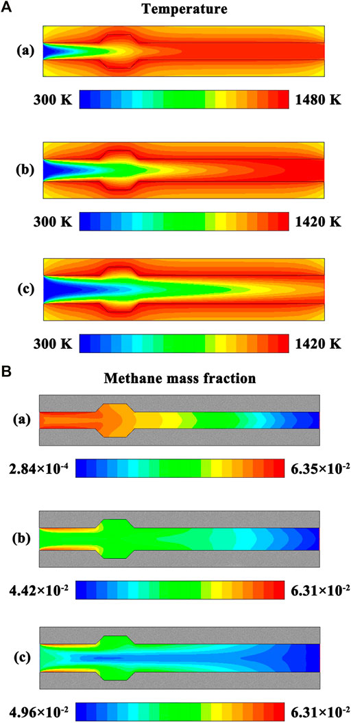
FIGURE 14. (A) Contour plots of temperature in the system under different channel height conditions. The channel height is specified as follows: (a) 3.0 mm, (b) 4.0 mm, and (c) 5.0 mm. The system is designed in stoichiometric operation, the exterior heat loss coefficient is 20 W/(m2⋅K), the thermal conductivity is 1.4 W/(m⋅K) for the solid material, and the flow velocity of the fluid is 0.3 m/s at the flow inlet; (B) Contour plots of methane concentration in the system under different channel height conditions. The channel height is specified as follows: (a) 3.0 mm, (b) 4.0 mm, and (c) 5.0 mm. The system is designed in stoichiometric operation, the exterior heat loss coefficient is 20 W/(m2⋅K), the thermal conductivity is 1.4 W/(m⋅K) for the solid material, and the flow velocity of the fluid is 0.3 m/s at the flow inlet.
As the spacing distance increases, the location of the flame moves towards the channel walls, as illustrated in Figures 14A,B. This is because a portion of heat of reaction during the combustion process is transferred to the upstream structure of the system by heat conduction through the channel walls, as discussed above. As the spacing distance increases, the maximum temperature decreases, as illustrated in Figure 14A, and incomplete combustion occurs within the system, as illustrated in Figure 14B. The length scale of the system is small enough in the transverse direction, when the spacing distance is small. As a result, the heat transfer in the transverse direction greatly affects the temperature profile along the fluid centerline. In this case, the temperature of the fluid is higher than that when the spacing distance is large, and combustion is nearly complete within the system.
As the spacing distance is decreased to 2.7 mm, the flame is very unstable. As the spacing distance is further decreased to 2.5 mm, the flame cannot be sustained and flame extinction typically occurs. Therefore, the quenching distance takes 2.5 mm for the system, which is in consistence with that determined by the experiments, as described above. To make the system operate effectively, there is a need to restrict the channel dimensions above the quenching distance. The flame cannot be sustained when the system operates near the extinction limit. As the spacing distance decreases below the quenching distance, flame propagation is impossible within the millimeter-scale system due to thermal and radical quenching (Jarosiński, 1983; Jarosinski, 1986). The high surface to volume ratio of the system will serve to inherently suppress or partially quench the flame (Popp et al., 1996; Bai et al., 2013). In contrast, the two trapezoidal cavities might mitigate influences of thermal and radical quenching. However, the results presented above indicate that the cavity structure has little effect on the quenching distance.
Conclusion
This study was focused mainly upon the essential combustion characteristics of methane-air mixtures in millimeter-scale systems with a cavity structure. Combustion characteristics and system performance were investigated both experimentally and numerically. Stable temperature profiles were obtained from thermographic measurements. Detailed kinetics were used for modeling the system in computational fluid dynamics. Numerical simulations were performed to better understand the stabilization mechanism of a flame within spaces with extremely small dimensions. Of particular concern were the essential factors for design considerations of the millimeter-scale systems with improved flame stability and combustion characteristics. The following major conclusions can be drawn from this study.
• The quenching distance of the methane flame is 2.5 mm for the systems with a cavity structure, which is slightly larger than commonly believed. The cavity structure has little effect on the quenching distance.
• However, the utilization of cavities can improve the efficiency and performance of the systems considerably, including flame stability and temperatures.
• The cavity structure will lead to a wider operating range in terms of the lean and rich flammability limits, with improved flame stability.
• The length scale of the systems plays a vital role in stabilizing the flame within spaces with extremely small dimensions.
• The thermal conductivity of the solid material has a significant effect on the efficiency and performance of the systems. The solid material is advantageously thermally conductive to permit a high wall temperature with more uniform distribution. The solid material with anisotropic thermal conductivity prevents transverse heat losses but allows longitudinal heat conduction, thereby further improving efficiency and performance for the systems.
• Unstable combustion conditions resulting from serious heat losses can be substantially reduced or eliminated by using a solid material that has anisotropic thermal conductivity. This design has great advantages in improving the efficiency and performance of the systems.
• The flow velocity of the fluid is an important factor affecting the efficiency and performance of the systems. stable combustion is restricted to a relatively narrow range of flow velocities.
• There is necessity of maintaining the fuel-to-air equivalence ratio in the flammable range, and consequently loss of flame stability due to variations in the fuel-to-air equivalence ratio can cause serious problems. Preferentially, the systems are designed in stoichiometric operation.
Data Availability Statement
The raw data supporting the conclusion of this article will be made available by the authors, without undue reservation.
Author Contributions
JC contributed to conception and design of the study. JC and TL developed the model and performed the analysis. JC wrote the manuscript. All authors read and approved the submitted version.
Funding
This work was supported by the National Natural Science Foundation of China (No. 51506048).
Conflict of Interest
The authors declare that the research was conducted in the absence of any commercial or financial relationships that could be construed as a potential conflict of interest.
Publisher’s Note
All claims expressed in this article are solely those of the authors and do not necessarily represent those of their affiliated organizations, or those of the publisher, the editors and the reviewers. Any product that may be evaluated in this article, or claim that may be made by its manufacturer, is not guaranteed or endorsed by the publisher.
References
Abdallah, M. S., Mansour, M. S., and Allam, N. K. (2021). Mapping the Stability of Free-Jet Biogas Flames under Partially Premixed Combustion. Energy 220, 119749. doi:10.1016/j.energy.2020.119749
ANSYS (2018). ANSYS FLUENT User's Guide. Release 19.2. Canonsburg, Pennsylvania, United States: ANSYS Inc.
Aravind, G. P., and Deepu, M. (2020). Numerical Studies on Convective Mass Transfer Augmentation in High-Speed Flows with Lateral Sweep Vortex Generator and Dimple Cavity. Int. J. Therm. Sci. 153, 106379. doi:10.1016/j.ijthermalsci.2020.106379
ASTM International (2016). ASTM E681-09(2015). Standard Test Method for Concentration Limits of Flammability of Chemicals (Vapors and Gases). West Conshohocken, Pennsylvania, United States: ASTM International. ICS Code: 13.300. doi:10.1520/E0681-09R15
ASTM International (2021). ASTM E582-21. Standard Test Method for Minimum Ignition Energy and Quenching Distance in Gaseous Mixtures. West Conshohocken, Pennsylvania, United States: ASTM International. ICS Code: 71.100.20. doi:10.1520/E0582-21
Bai, B., Chen, Z., Zhang, H., and Chen, S. (2013). Flame Propagation in a Tube with wall Quenching of Radicals. Combust. Flame 160 (12), 2810–2819. doi:10.1016/j.combustflame.2013.07.008
Bowman, C. T. (1992). Control of Combustion-Generated Nitrogen Oxide Emissions: Technology Driven by Regulation. Symp. (International) Combust. 24 (1), 859–878. doi:10.1016/s0082-0784(06)80104-9
Bradley, D., Shehata, M., Lawes, M., and Ahmed, P. (2020). Flame Extinctions: Critical Stretch Rates and Sizes. Combust. Flame 212, 459–468. doi:10.1016/j.combustflame.2019.11.013
Broda, J. C., Seo, S., Santoro, R. J., Shirhattikar, G., and Yang, V. (1998). An Experimental Study of Combustion Dynamics of a Premixed Swirl Injector. Symp. (International) Combust. 27 (2), 1849–1856. doi:10.1016/s0082-0784(98)80027-1
Bychkov, V. V., and Liberman, M. A. (2000). Dynamics and Stability of Premixed Flames. Phys. Rep. 325 (4-5), 115–237. doi:10.1016/s0370-1573(99)00081-2
Cam, O., Yilmaz, H., Tangoz, S., and Yilmaz, I. (2017). A Numerical Study on Combustion and Emission Characteristics of Premixed Hydrogen Air Flames. Int. J. Hydrogen Energ. 42 (40), 25801–25811. doi:10.1016/j.ijhydene.2017.07.017
Chang, L., Cao, Z., Fu, B., Lin, Y., and Xu, L. (2020). Lean Blowout Detection for bluff-body Stabilized Flame. Fuel 266, 117008. doi:10.1016/j.fuel.2020.117008
Char, J.-M., and Yeh, J.-H. (1996). The Measurement of Open Propane Flame Temperature Using Infrared Technique. J. Quant. Spectrosc. Radiat. Transf. 56 (1), 133–144.
Choi, J., Rajasegar, R., Mitsingas, C. M., Liu, Q., Lee, T., and Yoo, J. (2020). Effect of Flame Interaction on Swirl-Stabilized Mesoscale Burner Array Performance. Energy 2020, 116661. doi:10.1016/j.energy.2019.116661
Dunn-Rankin, D., Leal, E. M., and Walther, D. C. (2005). Personal Power Systems. Prog. Energ. Combust. Sci. 31 (5-6), 422–465. doi:10.1016/j.pecs.2005.04.001
El-Asrag, H., and Menon, S. (2007). Large Eddy Simulation of bluff-body Stabilized Swirling Non-premixed Flames. Proc. Combust. Inst. 31 (2), 1747–1754. doi:10.1016/j.proci.2006.07.251
Fan, A., Zhang, H., and Wan, J. (2017). Numerical Investigation on Flame Blow-Off Limit of a Novel Microscale Swiss-roll Combustor with a bluff-body. Energy 123, 252–259. doi:10.1016/j.energy.2017.02.003
Fan, A., Xiang, Y., Yang, W., and Li, L. (2018). Enhancement of Hydrogen Combustion Efficiency by Helium Dilution in a Micro-combustor with wall Cavities. Chem. Eng. Process. Process Intensification 130, 201–207. doi:10.1016/j.cep.2018.06.014
Fernandez-Pello, A. C. (2002). Micropower Generation Using Combustion: Issues and Approaches. Proc. Combust. Inst. 29 (1), 883–899. doi:10.1016/s1540-7489(02)80113-4
Fugger, C. A., Gallagher, T. P., Sykes, J. P., and Caswell, A. W. (2020). Spanwise Recirculation Zone Structure of a bluff Body Stabilized Flame. Combust. Flame 216, 58–61. doi:10.1016/j.combustflame.2020.02.002
Gatti, M., Gaudron, R., Mirat, C., Zimmer, L., and Schuller, T. (2019). Impact of Swirl and bluff-body on the Transfer Function of Premixed Flames. Proc. Combust. Inst. 37 (4), 5197–5204. doi:10.1016/j.proci.2018.06.148
Grib, S. W., Owens, T. C., and Renfro, M. W. (2020). Numerical Analysis of Flame Stabilization for a Steady Premixed Jet in Vitiated Coflow. Combust. Flame 221, 201–211. doi:10.1016/j.combustflame.2020.07.040
Gupta, A., Qadri, U. A., Koutita, K., Zadrazil, I., Hussain, T., Balachandran, R., et al. (2020). Experimental Investigation of the Flow in a Micro-channelled Combustor and its Relation to Flame Behaviour. Exp. Therm. Fluid Sci. 116, 110105. doi:10.1016/j.expthermflusci.2020.110105
Han, X., Laera, D., Yang, D., Zhang, C., Wang, J., Hui, X., et al. (2020). Flame Interactions in a Stratified Swirl Burner: Flame Stabilization, Combustion Instabilities and Beating Oscillations. Combust. Flame 212, 500–509. doi:10.1016/j.combustflame.2019.11.020
Hatem, F. A., Alsaegh, A. S., Al-Faham, M., Valera-Medina, A., Chong, C. T., and Hassoni, S. M. (2018). Enhancing Flame Flashback Resistance against Combustion Induced Vortex Breakdown and Boundary Layer Flashback in Swirl Burners. Appl. Energ. 230, 946–959. doi:10.1016/j.apenergy.2018.09.055
Huang, B., Li, H., Xia, S., and Xu, T. (2020). Experimental Investigation of the Flow and Heat Transfer Performance in Micro-channel Heat Exchangers with Cavities. Int. J. Heat Mass Transfer 159, 120075. doi:10.1016/j.ijheatmasstransfer.2020.120075
Jarosinski, J. (1986). A Survey of Recent Studies on Flame Extinction. Prog. Energ. Combust. Sci. 12 (2), 81–116. doi:10.1016/0360-1285(86)90014-6
Jeong, C., Bae, J., Kim, T., Yoon, J., Joo, S., and Yoon, Y. (2017). Investigation of Flashback Characteristics Coupled with Combustion Instability in Turbulent Premixed bluff Body Flames Using High-Speed OH-PLIF and PIV. Proc. Combust. Inst. 36 (2), 1861–1868. doi:10.1016/j.proci.2016.08.077
Jiaqiang, E., Ding, J., Chen, J., Liao, G., Zhang, F., and Luo, B. (2021). Process in Micro-combustion and Energy Conversion of Micro Power System: A Review. Energ. Convers. Manage. 246, 114664. doi:10.1016/j.enconman.2021.114664
Jiaqiang, E., Luo, B., Han, D., Chen, J., Liao, G., Zhang, F., et al. (2022). A Comprehensive Review on Performance Improvement of Micro Energy Mechanical System: Heat Transfer, Micro Combustion and Energy Conversion. Energy 239, 122509. doi:10.1016/j.energy.2021.122509
Ju, Y., and Maruta, K. (2011). Microscale Combustion: Technology Development and Fundamental Research. Prog. Energ. Combust. Sci. 37 (6), 669–715. doi:10.1016/j.pecs.2011.03.001
Kaisare, N. S., and Vlachos, D. G. (2012). A Review on Microcombustion: Fundamentals, Devices and Applications. Prog. Energ. Combust. Sci. 38 (3), 321–359. doi:10.1016/j.pecs.2012.01.001
Kang, D. G., Ko, H., Koo, J., Lim, S. I., Kim, J. S., Yu, Y. T., et al. (2018). Anisotropic thermal Interface Materials: Directional Heat Transfer in Uniaxially Oriented Liquid crystal Networks. ACS Appl. Mater. Inter. 10 (41), 35557–35562. doi:10.1021/acsami.8b09982
Kennedy, L. A., Bingue, J. P., Saveliev, A. V., Fridman, A. A., and Foutko, S. I. (2000). Chemical Structures of Methane-Air Filtration Combustion Waves for Fuel-Lean and Fuel-Rich Conditions. Proc. Combust. Inst. 28 (1), 1431–1438. doi:10.1016/s0082-0784(00)80359-8
Khateeb, A. A., Guiberti, T. F., Zhu, X., Younes, M., Jamal, A., and Roberts, W. L. (2020). Stability Limits and NO Emissions of Technically-Premixed Ammonia-Hydrogen-Nitrogen-Air Swirl Flames. Int. J. Hydrogen Energ. 45 (41), 22008–22018. doi:10.1016/j.ijhydene.2020.05.236
Khateeb, A. A., Guiberti, T. F., Wang, G., Boyette, W. R., Younes, M., Jamal, A., et al. (2021). Stability Limits and NO Emissions of Premixed Swirl Ammonia-Air Flames Enriched with Hydrogen or Methane at Elevated Pressures. Int. J. Hydrogen Energ. 46 (21), 11969–11981. doi:10.1016/j.ijhydene.2021.01.036
Kim, K. T., and Santavicca, D. A. (2013). Interference Mechanisms of Acoustic/convective Disturbances in a Swirl-Stabilized Lean-Premixed Combustor. Combust. Flame 160 (8), 1441–1457. doi:10.1016/j.combustflame.2013.02.022
Krishna, S., and Ravikrishna, R. V. (2015). Optical Diagnostics of Fuel-Air Mixing and Vortex Formation in a Cavity Combustor. Exp. Therm. Fluid Sci. 61, 163–176. doi:10.1016/j.expthermflusci.2014.10.012
Li, L., Yang, W., and Fan, A. (2019). Effect of the Cavity Aft Ramp Angle on Combustion Efficiency of Lean Hydrogen/air Flames in a Micro Cavity-Combustor. Int. J. Hydrogen Energ. 44 (11), 5623–5632. doi:10.1016/j.ijhydene.2018.07.162
Maruta, K. (2011). Micro and Mesoscale Combustion. Proc. Combust. Inst. 33 (1), 125–150. doi:10.1016/j.proci.2010.09.005
Mendiburu, A. Z., de Carvalho, J. A., Coronado, C. R., and Roberts, J. J. (2017). Flammability Limits Temperature Dependence of Pure Compounds in Air at Atmospheric Pressure. Energy 118, 414–424. doi:10.1016/j.energy.2016.12.036
Michaels, D., and Ghoniem, A. F. (2018). Leading Edge Dynamics of Lean Premixed Flames Stabilized on a bluff Body. Combust. Flame 191, 39–52. doi:10.1016/j.combustflame.2017.12.020
Miller, J. A., and Bowman, C. T. (1989). Mechanism and Modeling of Nitrogen Chemistry in Combustion. Prog. Energ. Combust. Sci. 15 (4), 287–338. doi:10.1016/0360-1285(89)90017-8
Morales, A. J., Lasky, I. M., Geikie, M. K., Engelmann, C. A., and Ahmed, K. A. (2019). Mechanisms of Flame Extinction and Lean Blowout of bluff Body Stabilized Flames. Combust. Flame 203, 31–45. doi:10.1016/j.combustflame.2019.02.002
Norton, D. G., and Vlachos, D. G. (2003). Combustion Characteristics and Flame Stability at the Microscale: a CFD Study of Premixed Methane/air Mixtures. Chem. Eng. Sci. 58 (21), 4871–4882. doi:10.1016/j.ces.2002.12.005
Norton, D. G., and Vlachos, D. G. (2004). A CFD Study of Propane/air Microflame Stability. Combust. Flame 138 (1-2), 97–107. doi:10.1016/j.combustflame.2004.04.004
Pan, M., Wang, H., Zhong, Y., Hu, M., Zhou, X., Dong, G., et al. (2019). Experimental Investigation of the Heat Transfer Performance of Microchannel Heat Exchangers with Fan-Shaped Cavities. Int. J. Heat Mass Transfer 134, 1199–1208. doi:10.1016/j.ijheatmasstransfer.2019.01.140
Panda, P. P., Busari, O., Roa, M., and Lucht, R. P. (2019). Flame Stabilization Mechanism in Reacting Jets in Swirling Vitiated Crossflow. Combust. Flame 207, 302–313. doi:10.1016/j.combustflame.2019.06.005
Pashchenko, D. (2017). Comparative Analysis of Hydrogen/air Combustion CFD-Modeling for 3D and 2D Computational Domain of Micro-cylindrical Combustor. Int. J. Hydrogen Energ. 42 (49), 29545–29556. doi:10.1016/j.ijhydene.2017.10.070
Pashchenko, D. (2020). Hydrogen-rich Fuel Combustion in a Swirling Flame: CFD-Modeling with Experimental Verification. Int. J. Hydrogen Energ. 45 (38), 19996–20003. doi:10.1016/j.ijhydene.2020.05.113
Peng, Q., Wu, Y., Jiaqiang, E., Yang, W., Xu, H., and Li, Z. (2019). Combustion Characteristics and thermal Performance of Premixed Hydrogen-Air in a Two-rearward-step Micro Tube. Appl. Energ. 242, 424–438. doi:10.1016/j.apenergy.2019.03.137
Popp, P., Smooke, M., and Baum, M. (1996). Heterogeneous-homogeneous Reaction and Transport Coupling during Flame-wall Interaction. Symp. (International) Combust. 26 (2), 2693–2700. doi:10.1016/s0082-0784(96)80105-6
Li, Q., Li, J., Shi, J., and Guo, Z. (2019). Effects of Heat Transfer on Flame Stability Limits in a Planar Micro-combustor Partially Filled with Porous Medium. Proc. Combust. Inst. 37 (4), 5645–5654. doi:10.1016/j.proci.2018.06.023
Sakurai, T., Yuasa, S., Honda, T., and Shimotori, S. (2009). Heat Loss Reduction and Hydrocarbon Combustion in Ultra-micro Combustors for Ultra-micro Gas Turbines. Proc. Combust. Inst. 32 (2), 3067–3073. doi:10.1016/j.proci.2008.06.002
Schmidt, H. (1909). Prüfung der strahlungsgesetze der bunsenflamme. Annalen der Physik 334 (10), 971–1028. doi:10.1002/andp.19093341008
Shanbhogue, S. J., Husain, S., and Lieuwen, T. (2009). Lean Blowoff of bluff Body Stabilized Flames: Scaling and Dynamics. Prog. Energ. Combust. Sci. 35 (1), 98–120. doi:10.1016/j.pecs.2008.07.003
Smith, G. P., Golden, D. M., Frenklach, M., Moriarty, N. W., Eiteneer, B., Goldenberg, M., et al. (2000). GRI-MECH 3.0. Chicago, Illinois, United States: The Gas Research Institute.
Song, K. H., Nag, P., Litzinger, T. A., and Haworth, D. C. (2003). Effects of Oxygenated Additives on Aromatic Species in Fuel-Rich, Premixed Ethane Combustion: A Modeling Study. Combust. Flame 135 (3), 341–349. doi:10.1016/s0010-2180(03)00180-9
Tian, X., Itkis, M. E., Bekyarova, E. B., and Haddon, R. C. (2013). Anisotropic thermal and Electrical Properties of Thin thermal Interface Layers of Graphite Nanoplatelet-Based Composites. Scientific Rep. 3 (1), 1710. doi:10.1038/srep01710
Tong, Y., Liu, X., Wang, Z., Richter, M., and Klingmann, J. (2018). Experimental and Numerical Study on bluff-body and Swirl Stabilized Diffusion Flames. Fuel 217, 352–364. doi:10.1016/j.fuel.2017.12.061
Walther, D. C., and Ahn, J. (2011). Advances and Challenges in the Development of Power-Generation Systems at Small Scales. Prog. Energ. Combust. Sci. 37 (5), 583–610. doi:10.1016/j.pecs.2010.12.002
Wan, J., and Fan, A. (2021). Recent Progress in Flame Stabilization Technologies for Combustion-Based Micro Energy and Power Systems. Fuel 286, 119391. doi:10.1016/j.fuel.2020.119391
Wan, J., and Zhao, H. (2020). Effect of thermal Condition of Solid wall on the Stabilization of a Preheated and Holder-Stabilized Laminar Premixed Flame. Energy 200, 117548. doi:10.1016/j.energy.2020.117548
Wan, J., and Zhao, H. (2020). Anomalous Blow-Off Limit of Methane-Air Premixed Flame in a Micro Preheated Combustor with a Flame Holder. Int. J. Hydrogen Energ. 45 (55), 31202–31212. doi:10.1016/j.ijhydene.2020.08.130
Wan, J., and Zhao, H. (2020). Blow-off Mechanism of a Holder-Stabilized Laminar Premixed Flame in a Preheated Mesoscale Combustor. Combust. Flame 220, 358–367. doi:10.1016/j.combustflame.2020.07.012
Wan, J., and Zhao, H. (2020). Blowout Limit of Premixed Flame in a Micro Preheated Combustor with a Flame Holder at Different Blockage Ratios. Int. J. Hydrogen Energ. 45 (46), 25468–25478. doi:10.1016/j.ijhydene.2020.06.257
Wan, J., Fan, A., Yao, H., and Liu, W. (2015). Effect of thermal Conductivity of Solid wall on Combustion Efficiency of a Micro-combustor with Cavities. Energ. Convers. Manage. 96, 605–612. doi:10.1016/j.enconman.2015.03.030
Wan, J., Song, J., Yang, Z., Kirsch, D., Jia, C., Xu, R., et al. (2017). Highly Anisotropic Conductors. Adv. Mater. 29 (41), 1703331. doi:10.1002/adma.201703331
Wang, S., and Fan, A. (2021). Combustion Regimes of Syngas Flame in a Micro Flow Reactor with Controlled Temperature Profile: A Numerical Study. Combust. Flame 230, 111457. doi:10.1016/j.combustflame.2021.111457
Wang, H., Ding, D., Liu, Q., Chen, Y., and Zhang, Q. (2019). Highly Anisotropic Thermally Conductive Polyimide Composites via the Alignment of boron Nitride Platelets. Compos. B Eng. 158, 311–318. doi:10.1016/j.compositesb.2018.09.104
Wang, M., Li, P., and Wang, F. (2020). Dependence of the Blowout Limit on Flow Structure, Heat Transfer, and Pressure Loss in a bluff-body Micro-combustor. Int. J. Hydrogen Energ. 45 (38), 19912–19925. doi:10.1016/j.ijhydene.2020.04.113
Wang, D., Qian, X., Ji, T., Jing, Q., Zhang, Q., and Yuan, M. (2021). Flammability Limit and Explosion Energy of Methane in Enclosed Pipeline under Multi-phase Conditions. Energy 217, 119355. doi:10.1016/j.energy.2020.119355
Westbrook, C. K., Adamczyk, A. A., and Lavoie, G. A. (1981). A Numerical Study of Laminar Flame wall Quenching. Combust. Flame 40, 81–99. doi:10.1016/0010-2180(81)90112-7
Westbrook, C. K., Mizobuchi, Y., Poinsot, T. J., Smith, P. J., and Warnatz, J. (2005). Computational Combustion. Proc. Combust. Inst. 30 (1), 125–157. doi:10.1016/j.proci.2004.08.275
Xu, F., Yan, Y., He, Z., Yang, Z., and Zhang, L. (2021). Numerical Study on the Influence of Controllable Flow Ratio on Combustion Characteristics of a Controllable central Slotted bluff Body and Cavity Combined Micro Combustor. Int. J. Hydrogen Energ. 46 (9), 6901–6914. doi:10.1016/j.ijhydene.2020.11.117
Yakovenko, I. S., and Kiverin, A. D. (2021). Intensification Mechanisms of the Lean Hydrogen-Air Combustion via Addition of Suspended Micro-droplets of Water. Int. J. Hydrogen Energ. 46 (1), 1259–1272. doi:10.1016/j.ijhydene.2020.09.234
Yan, Y., Wu, G., Huang, W., Zhang, L., Li, L., and Yang, Z. (2019). Numerical Comparison Study of Methane Catalytic Combustion Characteristic between Newly Proposed Opposed Counter-flow Micro-combustor and the Conventional Ones. Energy 170, 403–410. doi:10.1016/j.energy.2018.12.114
Yang, X., Zhao, L., He, Z., Dong, S., and Tan, H. (2019). Comparative Study of Combustion and thermal Performance in a Swirling Micro Combustor under Premixed and Non-premixed Modes. Appl. Therm. Eng. 160, 114110. doi:10.1016/j.applthermaleng.2019.114110
Yilmaz, H., Cam, O., and Yilmaz, I. (2017). Effect of Micro Combustor Geometry on Combustion and Emission Behavior of Premixed Hydrogen/air Flames. Energy 135, 585–597. doi:10.1016/j.energy.2017.06.169
Yilmaz, H., Cam, O., and Yilmaz, I. (2020). A Comparison Study on Combustion and Emission Characteristics of Actual Synthetic Gas Mixtures. Fuel 263, 116712. doi:10.1016/j.fuel.2019.116712
Yilmaz, H. (2019). Investigation of Combustion and Emission Performance of a Micro Combustor: Effects of bluff Body Insertion and Oxygen Enriched Combustion Conditions. Int. J. Hydrogen Energ. 44 (47), 25985–25999. doi:10.1016/j.ijhydene.2019.08.045
Zangeneh, V., and Alipoor, A. (2021). Stability Study of Hydrogen-Air Flame in a Conical Porous Burner. Energy 215, 119140. doi:10.1016/j.energy.2020.119140
Zhang, Z., Wu, K., Yuen, R., Yao, W., and Wang, J. (2020). Numerical Investigation on the Performance of bluff Body Augmented Micro Cavity-Combustor. Int. J. Hydrogen Energ. 45 (7), 4932–4945. doi:10.1016/j.ijhydene.2019.12.004
Zhang, Z., Wu, K., Yao, W., Yuen, R., and Wang, J. (2020). Enhancement of Combustion Performance in a Microchannel: Synergistic Effects of bluff-body and Cavity. Fuel 265, 116940. doi:10.1016/j.fuel.2019.116940
Zhao, M., and Fan, A. (2020). Buoyancy Effects on Hydrogen Diffusion Flames Confined in a Small Tube. Int. J. Hydrogen Energ. 45 (38), 19926–19935. doi:10.1016/j.ijhydene.2020.05.010
Keywords: micro-combustion, combustor design, combustion characteristics, methane flames, flame stability, computational fluid dynamics
Citation: Chen J and Li T (2022) Combustion Characteristics of Methane-Air Mixtures in Millimeter-Scale Systems With a Cavity Structure: An Experimental and Numerical Study. Front. Energy Res. 10:807902. doi: 10.3389/fenrg.2022.807902
Received: 02 November 2021; Accepted: 21 January 2022;
Published: 02 March 2022.
Edited by:
Lei Luo, Harbin Institute of Technology, ChinaReviewed by:
Liqiao Jiang, Guangzhou Institute of Energy Conversion (CAS), ChinaWei Du, Harbin Institute of Technology, China
Copyright © 2022 Chen and Li. This is an open-access article distributed under the terms of the Creative Commons Attribution License (CC BY). The use, distribution or reproduction in other forums is permitted, provided the original author(s) and the copyright owner(s) are credited and that the original publication in this journal is cited, in accordance with accepted academic practice. No use, distribution or reproduction is permitted which does not comply with these terms.
*Correspondence: Junjie Chen, Y29tY2pqQDE2My5jb20=, Y2pqQGhwdS5lZHUuY24=
 Junjie Chen
 Tengfei Li