 Mohamed H. Mohamed
 Faris Alqurashi
 A. Ramadan
 D. Thévenin5
94% of researchers rate our articles as excellent or good
Learn more about the work of our research integrity team to safeguard the quality of each article we publish.
Find out more
ORIGINAL RESEARCH article
Front. Energy Res., 25 April 2022
Sec. Wind Energy
Volume 10 - 2022 | https://doi.org/10.3389/fenrg.2022.797868
This article is part of the Research TopicAerodynamic Upgrades of Wind Turbines and Wind FarmsView all 5 articles
In this work, the performance of a new wind turbine design derived from a conventional Savonius turbine is investigated by numerical simulations. The new design consists of three blades without passage between them (closed center). All unsteady computations (which mean computational fluid dynamics as well in the next sections) presented in the current work depend on a commercial software ANSYS Fluent 19. In particular, the blade geometry, the influence of a deflecting plate, and the influence of mobile parts on the returning plate have been investigated in detail. Since first results were partly disappointing for the turbine with a deflector but very interesting for the turbine with an opening blade, these same properties have also been investigated for the classical Savonius turbine. By comparison between both, an optimal solution can emerge from this first study for these designs. The results indicated that the opening blade design improved the performance by 25.9% at λ = 0.7; however, the deflecting plate reduces the performance along the operating range.
Due to the deep energy crisis in the world, research studies and development activities in the field of renewable energies and especially wind energy have considerably increased during the last few years in many countries. Although wind energy technology has been greatly improved during that time, the available technical design is not enough to extract the wind energy and convert it into the mechanical energy for the conditions of the residential and remote areas which have low wind speeds. Savonius turbines (Figure 1) and derived configurations could be a very good solution for such conditions. This is the purpose of the present study.
Utilizing the details of Figure 1, the wind speed coefficient (tip speed ratio) was determined by
For the Savonius rotors of height H and a wind of upstream velocity U, the output power P and the output torque on the shaft of a Savonius turbine can, respectively, be written as follows:
and
where Cp and Cm are, respectively, the output power coefficient and the output torque coefficient. In the following lines, Savonius rotors are called conventional or standard Savonius rotors if the geometrical factors a and e are, respectively, equal to 0 and d/6. This base configuration of the turbine was intensively investigated as in Menet and Nachida (2004). In particular, values of Cp and Cm were numerically calculated as a function of the tip speed ratio λ, allowing for a direct estimation of mechanical power and mechanical torque. Nevertheless, the values found by Menet and Nachida (2004) are unusually higher than those in the standard literature on the subject and must be considered with caution, since only very few details are given concerning the underlying procedure.
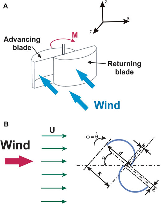
FIGURE 1. Standard Savonius turbine (A) and description and main parameters characterizing a Savonius rotor (B).
A lot of literature reports have appeared in the last two decades related to the Savonius turbine and its performance. The theoretical and experimental results concerning the performance of Savonius turbines in these previous publications have indicated that such turbines are interesting for some specific applications but show a very low efficiency. It is thus essential to increase the performance of these turbines. Therefore, several design improvements have been introduced to enhance the efficiency of the Savonius rotor (Menet and Nachida, 2004; Haddad et al., 2021; Huda et al., 1992; Saha and Rajkumar, 2006; Irabu and Roy, 2007; Menet, 2007; Mohamed et al., 2021). In the present study, we will study numerically the three-bladed design under the effect of the rounded deflector as well as the opening returning blade as a new concept derived for a Savonius turbine: it is a turbine consisting of three semi-cylindrical blades without a passage in between, as shown in Figure 2. This concept has been proposed in several publications (Haddad et al., 2021; Mohamed et al., 2021).
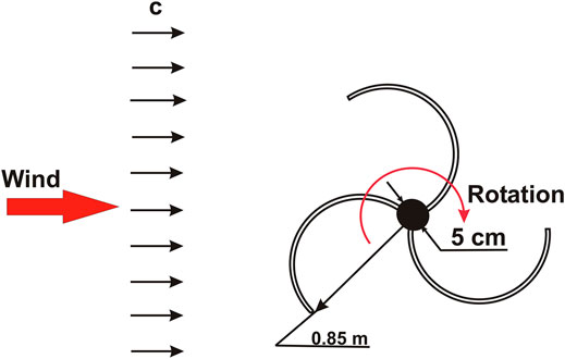
FIGURE 2. Schematic shape of the modified design.
For instance, Kamoji et al. (Kedare et al., 2009) studied the helical design of Savonius turbine to improve the performance, and they found that the helical shape enhanced the self-starting of the turbine. In 2006, Saha and Rajkumar investigated the twisted design of Savonius turbine, which improved the performance, but it is costly and complex design (Saha and Rajkumar, 2006). Installing a guide box around the rotor was studied by Irabu and Roy (2007), and it improved the three-blade rotor, but it has a very complex design. Iio et al. (2011) increased the performance by installing a shielding plate. Elbatran et al. (2017) found that installing a ducted nozzle increases the performance to get a maximum power coefficient equal to 0.25. Kerikous and Thévenin (2019) optimized the blade thickness to improve the performance, and they found that the relative increase was 12%. Dual splitters were added (Patel and Patel, 2021) to the blade of Savonius turbine to improve the aerodynamic distribution of the flow inside the blades, and they succeeded in increasing the performance by 7.3%. Ramadan et al. (2021) used the S-shape blade with a deflector to enhance the performance. This enhanced the performance, and the maximum power coefficient was 0.24. The self-staring of the three-blade rotor is studied by Salleh et al. (2021) by installing frontal guiding plates. Mohamed et al. (2021) optimized the position of the frontal guiding plates and its effect on the Savonius turbine performance, and they concluded that the guiding plates increased the maximum power coefficient to 0.31. Banerjee et al. (2014) studied the elliptic-bladed Savonius turbine, and they found that the elliptic-bladed Savonius turbine improved flow characteristics. The maximum power coefficient was enhanced by Banerjee (2019) to 0.25 using the elliptic-bladed Savonius design. The elliptic-shaped Savonius turbine was optimized by genetic algorithm techniques to optimize the blade’s profile to maximize the turbine performance (Paul and Banerjee, 2021a). An experimental investigation has been carried out by Paul and Banerjee (2021b) to test the performance of the elliptic-shaped Savonius turbine. A comparative study has been introduced by Paul and Banerjee (2021c) to investigate three different designs of Savonius turbines.
Within this work, the design is always treated in two dimensions, since there is no geometrical change along the third (vertical) direction (z-direction), and the coordinates are shown in Figure 1. Improving the performance of the three-bladed Savonius turbine is the main target of this study by different designs. The main parameter in this study is how to reduce the drag forces on the returning blades to reduce the negative torque and redirect the flow to the advanced blade to increase the positive torque, and the sequence increases the net torque of the turbine. The innovation in this work is the reduction of the negative torque by different designs such as movable parts in the returning blade and the deflector. Besides the Introduction, the outline of this study includes Materials and Methods which consists of all the numerical analysis of the used model, domain independence study, and mesh independence study. In Section 3, the results and discussions of all configurations are introduced after model validation. Finally, some qualitative and quantitative conclusions are provided in Section 4.
From the previous publication, it is noted that an accurate computational fluid dynamic simulation of the aerodynamic flow around the Savonius rotors is a complex and challenging mission, fundamentally, due to the rotor’s deeply time-dependent nature (Mohamed et al., 2008a; Mohamed et al., 2008b; Mohamed et al., 2010; Mohamed et al., 2011). Additionally, a strong separation around the blades plays a significant role for turbine efficiency and the power output. Therefore, the quality of the numerical simulations and the procedure should be checked with great care. Then, the methodology sequence must be validated and verified.
All aerodynamic flow simulations (which also denote computational fluid dynamics (CFD)) introduced in the current paper depend on the industrial software ANSYS Fluent 19.
The suitable dimensions of the computational domain have firstly been studied. It should be indeed investigated that these dimensions do not affect the results of simulations. A domain of size (square domain of dimensions 2L × 2L, normalized by the turbine radius R, as shown in Figure 3) has been checked in this step of the CFD computation. It is clear from Figure 3 that the last three larger domains lead to nearly fixed values, with a variation of the output torque less than 1.13%. This indicates the computational domain must extend at least over 20 times the turbine radius in each direction. In the same domain, the boundary conditions affecting the flow features are implemented in the same Figure 3 in an inappropriate manner. The velocity inlet and pressure outlet are governing the inlet and outlet of the domain; however, symmetry is located on both domain sides, and there is no effect of the blockage ratio. Finally, the employed domain (L/R = 27) marked in Figure 3 has been retained for all further rotor simulations in this work.
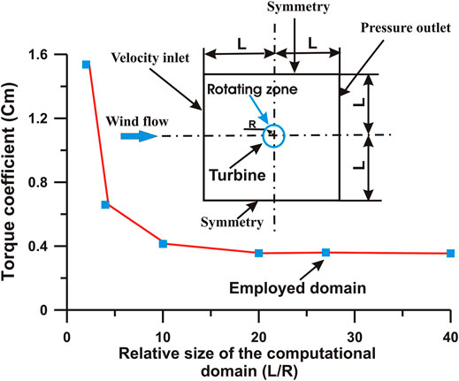
FIGURE 3. Computational domain and boundary conditions.
The SIMPLE (Semi-Implicit Method for Pressure-Linked Equations) algorithm is utilized to calculate the unsteady Reynolds-averaged Navier–Stokes equation for pressure–velocity coupling. Discretization of the aerodynamic flow parameters and the turbulent values are utilized in the finite-volume formulation with the second-order upwind scheme. The realizable k−ɛ model is used in this work as a turbulence model to calculate the flow characteristics inside the domain. The realizable k−ɛ model is recommended for rotating bodies (Mohamed et al., 2010; Mohamed et al., 2011). The realizable k–ϵ model usually provides improved results for swirling flows and flows involving separation when compared to the standard k–ϵ model. The realizable k–ϵ model has two differences than the standard k–ϵ model. First, it consists of a new formulation for the turbulent viscosity Cμ. Cμ is not fixed as in the standard k–ϵ model but a variable. Second, the realizable k–ϵ is a new transport equation for the dissipation rate, ɛ, which is derived from an exact equation for the transport of the mean-square vorticity fluctuation. As a result, it mainly improved predictions of several applications such as a superior ability to capture the mean flow of complex structures and for flows involving rotation, boundary layers under strong adverse pressure gradients, separation, and recirculation.
•Transport equations:
where
where S is the modulus of the mean rate of strain tensor.
In these equations, Pk represents the generation of turbulence kinetic energy due to the mean velocity gradients, calculated as follows:
Pb is the generation of turbulence kinetic energy due to buoyancy, negligible in our applications:
where Prt is the turbulent Prandtl number for energy and gi is the component of the gravitational vector in the ith direction. The default value of Prt is 0.85.
The coefficient of thermal expansion, β, is defined as
•Modeling turbulent viscosity:
While Cμ is constant in the standard k–ϵ model, this coefficient is calculated as follows in the realizable k–ϵ model:
and
where
where
•Model constants:
During the simulation of the current design, two-dimensional simulation is suitable (no geometry change in the third direction when the turbine has an end plate); therefore, that extremely fine and accurate grid can be utilized. Therefore, the sliding mesh model (SMM) is employed in the current work in the rotating zone, while the rest of the domain will be stationary. The sliding mesh model is the most accurate methodology for predicting the flow in multiple moving reference frames, but also computational time demanding. In the sliding mesh methodology, two cell zones are utilized. The mesh is generated in each zone independently, and it is needed to merge the mesh sides prior to starting the calculation. Each cell zone is bounded by one interface zone boundary condition where it meets the opposing cell zone. The interface zones of adjacent cell zones are associated with one another to form a mesh interface. The two cell zones will move relative to each other along the mesh interface. During the simulation, the zones slide (rotating in this paper) relative to one another along the mesh interface in discrete steps. As the rotation occurs, cell alignment along the mesh interface is not required. Since the flow is inherently unsteady, a time-dependent solution procedure is required.
An interface boundary condition is employed as a link between the stationary and rotating zones (see the domain in Figure 4). The interface boundary condition is used to link the stationary zone and the rotating zone. This link keeps the continuous flow through the two zones without any blockage.
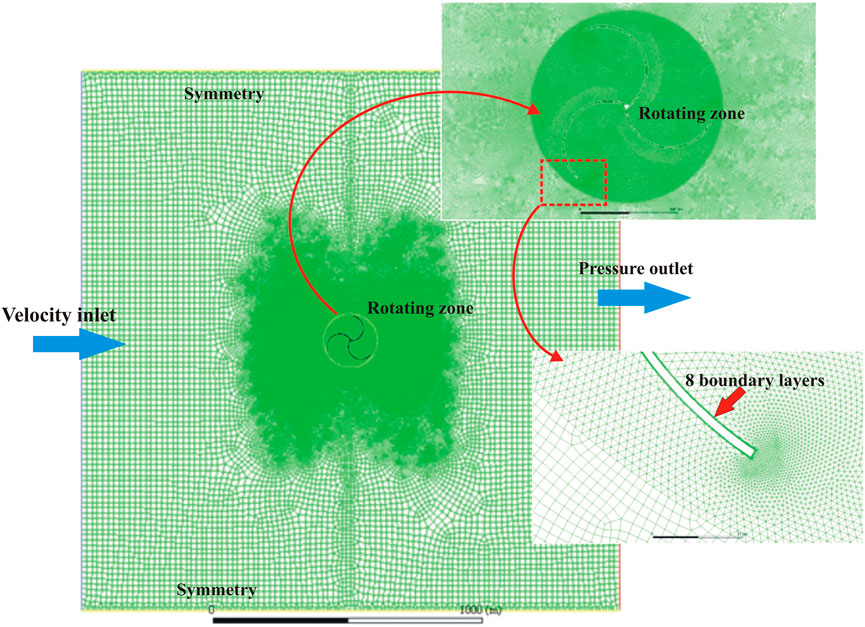
FIGURE 4. Mesh around the three-bladed Savonius turbine.
Four complete revolutions are always computed with a fixed time step equivalent to half of one degree of the azimuth angle. The first revolution is used to initiate the correct flow solutions. The remaining three revolutions are employed to calculate the turbine performance (in particular the power coefficient Cp and the torque coefficient Cm) by averaging the results of these three revolutions. By checking the results, it should be noted that the results are constant noticeably by further iteration with time. Every revolution takes around 360 min on the normal PC of computing time.
To complete the CFD setting accurately, the mesh independence study has been executed to eliminate the effect of the mesh from the results.
In Figure 5, several 2D grids of increasing density and quality, within the range of 6,000 up to 119,500 nodes, were examined for the Savonius rotor. This study indicated that 100 000 control volumes are appropriate to obtain accurate results of the simulation. It is clear to note from Figure 5 that a large deviation of torque coefficient appears for the five coarsest grids. However, all the remaining tested grids use more than 81,000 nodes which lead to a variance of the torque coefficient less than 1.4%. The acceptable mesh range between 86,000 and 95,000 nodes was retained in this work due to computation time of the simulation which obviously will increase speedily with the increasing number of grid cells.
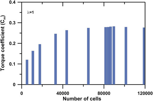
FIGURE 5. Independence study of the mesh for the turbine performance output.
Before investigating design modifications, the whole numerical model was validated by comparing the current model results with previous published experimental data (Hayashi et al., 2005) for a conventional Savonius rotor. It is a comparison between current numerical results of the three-bladed Savonius turbine with a passage in between and experimental results of the same conventional rotor (with a passage in between). After this comparison, the current model results shown in Figure 6 demonstrate the excellent agreement obtained between the present model results and the published experiment results for this conventional configuration, at least for λ > 0.3. It is clear in Figure 6 that both the torque and the power output coefficients are extremely well predicted. As a consequence, it is now possible to start the investigation of modifications of the Savonius turbine.
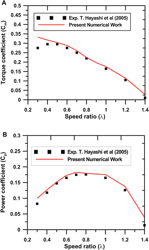
FIGURE 6. Validation of the current model: torque coefficients (A) and power coefficients (B), compared to experimental data (Hayashi et al., 2005).
Recently, a modified rotor design of the three blades without internal spaces between the blades was introduced by several publications, to enhance the performance of the standard rotor. After checking the performance of the three-bladed design as a geometry different from the conventional turbine, two attempts (opportunities) should be specifically studied in this work; therefore, the work scenario will go through the following steps:
1) In the elementary step, the performance of the three-bladed design is studied and compared with that of the conventional Savonius turbine.
2) The first opportunity is to improve the efficiency by using a rounded deflector plate to reduce negative torque on the rotor.
3) The second opportunity is to increase the performance by utilizing moving parts on the returning blades to reduce the negative torque.
In the primary step, the three-bladed design performance is investigated and compared with that of the conventional Savonius turbine. Therefore, we begin by considering the newly proposed design compared to the conventional turbine.
Figure 7 presents a performance comparison between the new design (known as the “three-bladed Savonius rotor without passage”) and the standard Savonius rotor. Unfortunately, it is clear from this comparison that the three-bladed Savonius turbine without passage has less performance (torque coefficient and power coefficient) than the conventional rotor. At low speed ratios λ, small differences appear; however, the difference is increased extremely by increasing the tip speed ratio λ. The maximum value of Cp is only 0.16 in comparison with 0.18 for the standard rotor (with a passage in between) with the reduction ratio equaling 11.1% based on the standard performance as the reference. This deviation is noted through the whole operating range (from λ = 0.4 to λ = 1.4). By analyzing the aerodynamics around the turbine, it is noted that the reason for this decrease in the performance is the closing of the passage between the blades, which leads to reduction in the incoming wind entering the turbine as presented in Figure 8. Furthermore, there is no effect of the number of blades on the reduction of the performance.
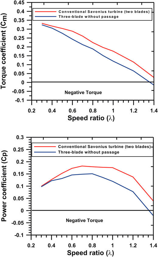
FIGURE 7. Performance comparison between the new design and the conventional Savonius rotor.
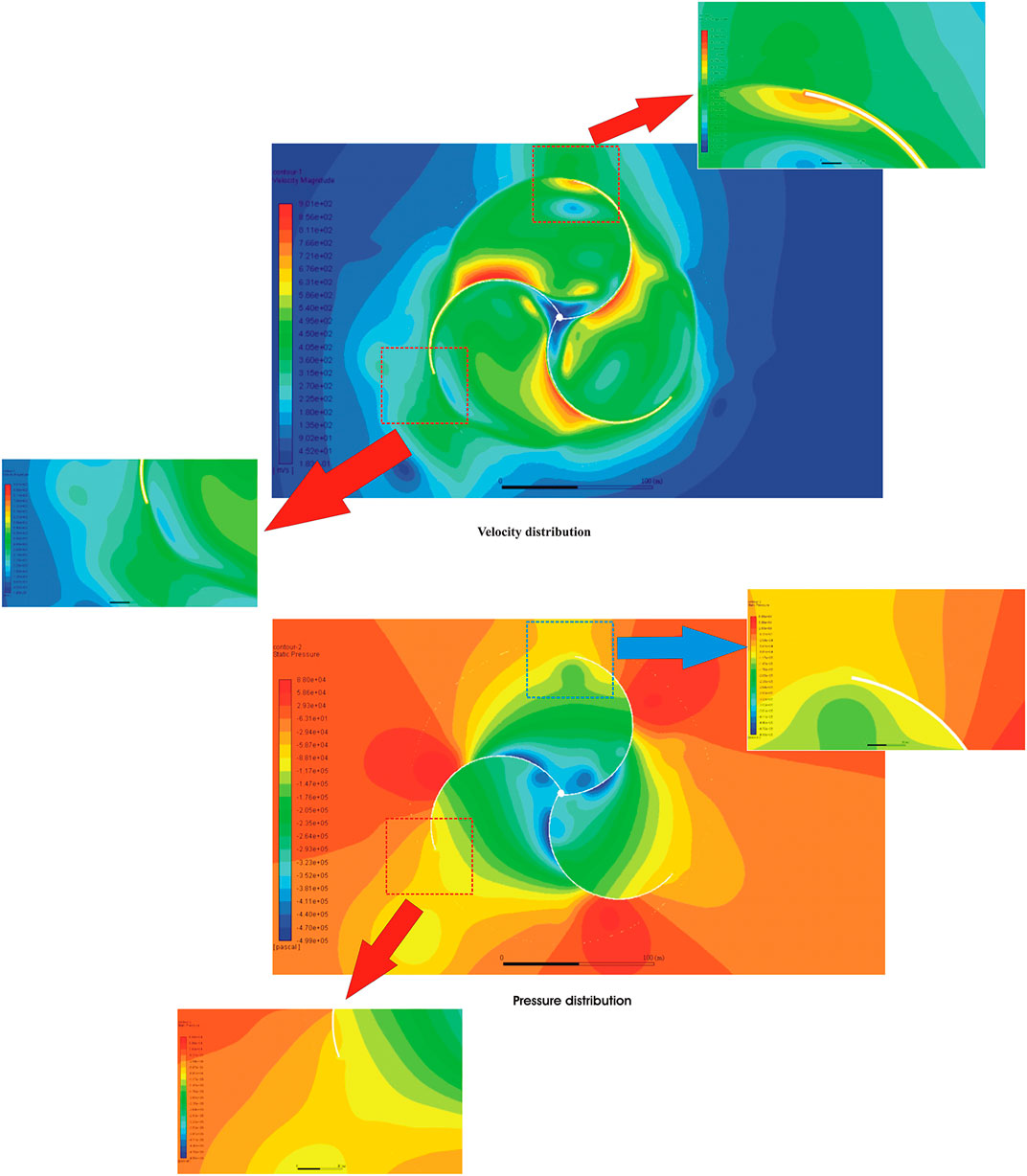
FIGURE 8. Instantaneous velocity distribution (m/s) and pressure distribution around the three-bladed design.
Self-starting is essential for decentralized, low-power applications as considered here. The investigation of the self-starting capability is obtained by studying the static torque on a non-moving turbine, varying the angle θ (see Figure 1). Figure 9 shows this static torque coefficient for the new design, as a function of the angle θ. For comparison, the experimental results of Irabu and Roy (2007) for a three-bladed Savonius turbine are also presented. It is observed that the new design leads to a large modification of the static torque coefficient. As expected, the static torque coefficient
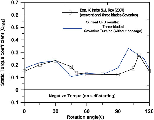
FIGURE 9. Static torque coefficient for the three-bladed Savonius design.
After studying the three-bladed Savonius turbine without passage, it is clear that, in a standard configuration, the three-bladed Savonius turbine without passage is less favorable than the conventional Savonius rotor. Therefore, further modifications are needed to increase the performance of this design. In addition, in order to allow for meaningful comparisons, these same modifications must also be considered for the conventional design.
Some authors introduced some ideas to improve the performance of the Savonius turbine by reducing the drag force on the returning blade (Haddad et al., 2021; Mohamed et al., 2021). In this paper, a unique idea is introduced to reduce the drag force on the returning blade by employing mobile blade sections. The movable parts will close, and the blade will return back to the conventional blade and work as an advancing blade. On the contrary, these movable parts will open when the blade rotates and works as a returning blade to reduce the negative torque on the returning blade. This sequence is discussed schematically in Figure 10.
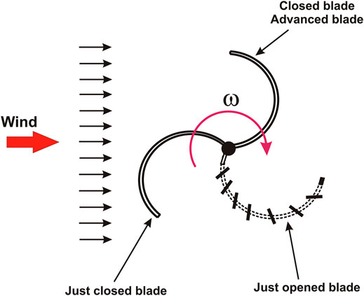
FIGURE 10. Schematic illustration of the new design with movable parts of returning blades.
This innovative design which deals with the opening returning blade was studied numerically for several values of the speed ratio λ. The blades consist of slits with a constant opening angle of 30° inclined from the baseline of the local conventional blade direction. Figure 11 presents the performance comparison of the new design (opening blade) with the conventional Savonius turbine. The results indicate a significant enhancement of the performance in comparison with that of the conventional design.
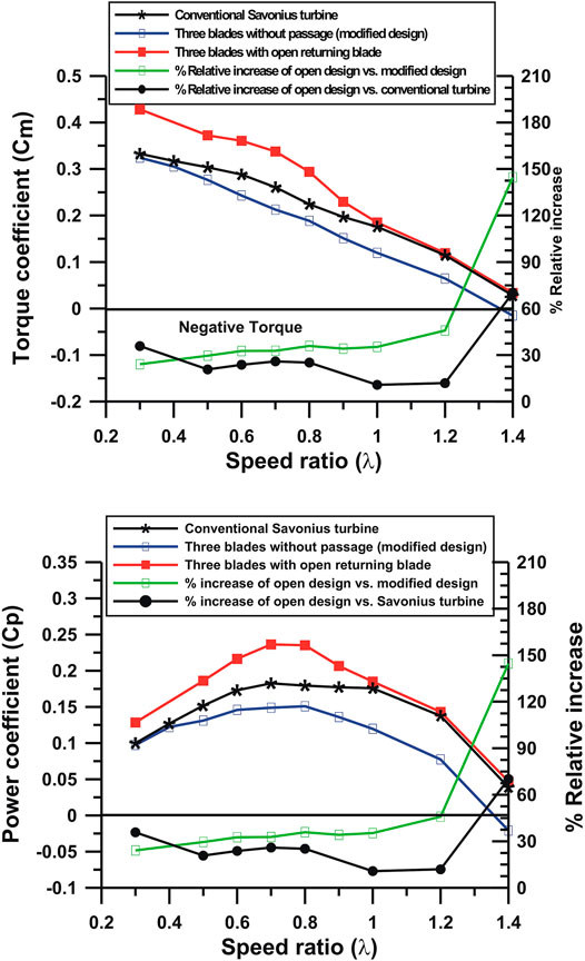
FIGURE 11. Three-bladed turbine performance with and without movable parts on the returning blades as well as the conventional Savonius rotor performance. Top: torque momentum. Bottom: power coefficient.
It is clear that the improvement occurs for the torque and for the power coefficient simultaneously. This gain is due to the deep reduction of the negative torque on the returning blade when the opening blade relieves the wind between the slits as shown in Figure 12. This relief flow on the returning blade reduces the drag forces on this blade, which leads to reduction of the negative torque. In addition, some of relief wind will flow back toward the advanced blade which enhances the mass flow rate impinging this blade and increases the positive torque as shown in Figure 12. The increase of the power output coefficient accomplishes 0.0853 at λ = 0.8. This means that a relative enhancement of performance by value equals 35.9%. However, this deviation is less after λ = 1.0: it equals 19.3%. This new design (opening returning blade) is extremely better than the standard Savonius rotor. For instance, at λ = 0.7, the relative increase (gain) in performance equals 25.9%, but after λ = 1.0, the power coefficient is identical approximately to that of the conventional Savonius rotor with a passage in between. Actually, experimental measurements are still needed on the wind-tunnel laboratory, in order to quantify the drag coefficient for the opened and closed configurations. At the end of this section, we can conclude that opening the returning blade leads to a considerable increase of performance for the new design. In addition, here, a fixed opening angle of 30° has been tested, and maybe by studying this angle, better values can be found. Furthermore, note that the same modification could possibly lead to even better results for the conventional Savonius turbine.
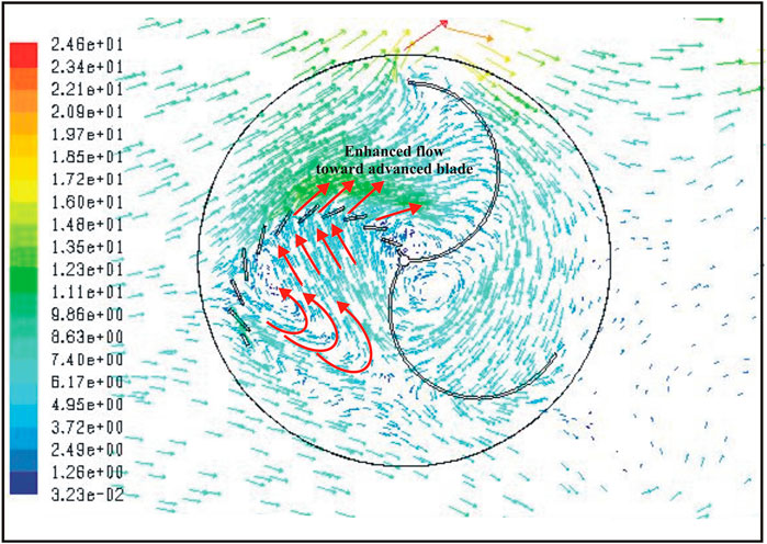
FIGURE 12. Instantaneous velocity vectors (m/s) around the new design with an open returning blade.
In the conceptual idea of the three-bladed Savonius turbine, a deflecting structure with diameter 1700 mm is placed in front of two counter-rotating turbines with a blockage ratio equal to 56.1% based on the new design as presented in Figure 13. This blockage will redirect the flow toward the advanced blade and cover the returning blade which leads to increasing the new torque. All the dimensions and the positions of the deflector and the turbines are illustrated in Figure 13. Due to the deflection of the wind flow (45°) toward the advanced blade, the performance of the counter-rotating turbines will be affected. The effect of this rounded deflector on the total performance is performed.
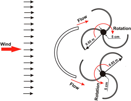
FIGURE 13. Schematic description of the modified design with a deflecting structure.
Figure 14 presents a comparison between a three-bladed Savonius turbine as a base design and the turbines placed behind the deflecting structure. It is noted the performance of the new system of deflector is less than that of the base design. For example, at λ = 0.7, the power coefficient has reduced from 0.13 to 0.1 with reduction deviation equaling 15.4%, and this trend is repeated all over the operating range as shown in Figure 14.
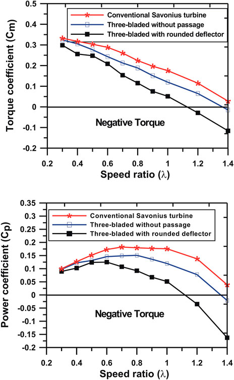
FIGURE 14. Deflecting structure effect on the performance of the three-bladed Savonius turbine.
In addition, the operating range (range of speed ratio) of the three-bladed turbine with a deflector is narrower than that of the three-bladed turbine without deflector, and the operating range (range of speed ratio) is reduced by 19%. Furthermore, the reduction in both the torque and power coefficients is clear. Actually, the size and large radius of the deflector are playing a main role in the reduction of the performance; this means the rounded deflector redirects the flow away from the advancing blade which leads to the reduction in the positive torque as shown in Figure 15. In addition, high pressure zones on the end points of the deflector have been detected due to the interaction between the deflector and the blades. This means the position of the deflector also should be studied and optimized. Therefore, it can be concluded that the deflecting structure is much too large in its present structure and some optimization work is still needed for the position of the deflector. Nevertheless, a companion study on the standard Savonius turbine shows that such a deflecting plate might be very beneficial, if placed at the right position; it is not sure that such a geometry leads to an optimal performance. Therefore, an optimization of this geometry based on splines should be performed.
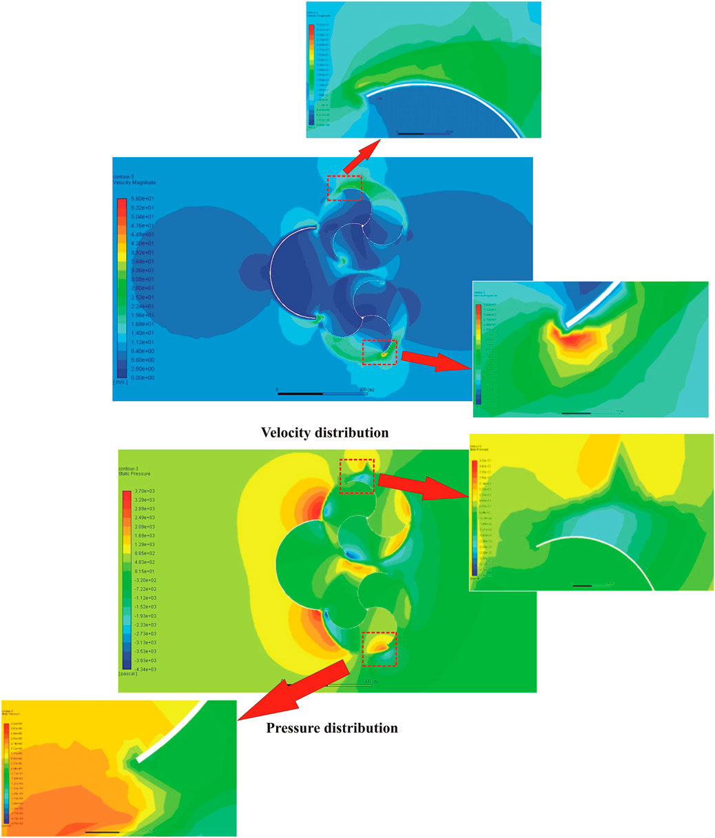
FIGURE 15. Instantaneous velocity distribution (m/s) and pressure distribution around the three-bladed design unsing deflecting structure.
This work investigates numerically a three-bladed Savonius design based on the conventional Savonius turbine, but involving three blades without a passage in between. Furthermore, a deflecting structure and the possibility of opening the returning blade were considered. This means that three different designs were studied in this paper and compared with the conventional three-blade Savonius turbine (with a passage in between). After finishing this work, several conclusions are already clear:
1) The three-bladed Savonius turbine (without a passage in between) is by itself less efficient than the conventional Savonius turbine (with a passage in between). It is noted that the reduction has increased deeply by increasing the tip speed ratio λ. The maximum value of Cp is only 0.16 in comparison with 0.18 for the standard rotor (with a passage in between) with the reduction ratio equaling 11.1%, and this deviation is noted through the whole operating range (from λ = 0.4 to λ = 1.4). However, the self-starting capability is comparable, but both torque and power coefficients are systematically and considerably lower.
2) By opening the returning blade, a considerable increase in performance can be observed. The new design becomes under such conditions more efficient than the conventional turbine. The increasing power output coefficient accomplishes 0.0853 at λ = 0.8. This means that a relative enhancement of performance by value equals 35.9%. However, this deviation is less after λ = 1.0, and it equals 19.3%.
3) This rotor with an opening returning blade is extremely better than the standard Savonius rotor (with a passage in between). For instance, at λ = 0.7, the relative increase (gain) in performance equals 25.9%, but after λ = 1.0, the power coefficient is identical approximately to that of the conventional Savonius rotor with a passage in between.
4) The proposed deflecting structure is too large and leads again to a loss of performance. For instance, at λ = 0.7, the power coefficient has reduced from 0.13 to 0.1, and this trend is repeated for all speed ratios with reduction deviation equaling 15.4%, and this trend is repeated all over the operating range.
Therefore, several recommendations can be given:
1) It is at this point not clear if the three-bladed turbine is really better than the conventional Savonius turbine. Both concepts should be further investigated, before taking a final decision. In particular, what would be the performance of the conventional Savonius turbine with an open returning blade?
2) The deflecting structure used in the first design should be reduced and modified to increase (and not reduce) the performance.
3) The deflecting structure and the open returning blade have a similar role for the system and are therefore not really compatible which depends on the reduction of the returning blade negative torque.
4) The possibility of optimizing the deflector size and opening design will be further improvements in performance as far as possible.
The raw data supporting the conclusion of this article will be made available by the authors, without undue reservation.
FA, AR, and DT conceptualized the research idea. MM, AR, and FA performed the methodology and wrote the original draft. MM validated the data and ran the software. DT supervised the work, curated the data, and reviewed and edited the paper.
This work was supported financially by a bursary of the University of Bisha, Saudi Arabia.
The authors declare that the research was conducted in the absence of any commercial or financial relationships that could be construed as a potential conflict of interest.
All claims expressed in this article are solely those of the authors and do not necessarily represent those of their affiliated organizations, or those of the publisher, the editors and the reviewers. Any product that may be evaluated in this article, or claim that may be made by its manufacturer, is not guaranteed or endorsed by the publisher.
The first author would like to thank the Deanship of Scientific Research at Umm Al-Qura University for supporting this work under Grant Code 22UQU4361231DSR03.
Banerjee, A., Roy, S., Ujjwal, K., and Mukherjee, S. P. (2014). “Unsteady Flow Analysis Around an Elliptic-Bladed Savonius-Style Wind Turbine,” in Gas Turbine India Conference (GTINDIA), GTINDIA2014-8141(V001T05A001):7 pages. doi:10.1115/gtindia2014-8141
Banerjee, A. (2019). Performance and Flow Analysis of an Elliptic Bladed Savonius-Style Wind Turbine. J. Renew. Sustain. Energ. 11, 033307.
Elbatran, A. H., Ahmed, Y. M., and Shehata, A. S. (2017). Performance Study of Ducted Nozzle Savonius Water Turbine, Comparison with Conventional Savonius Turbine. Energy 134, 566–584. doi:10.1016/j.energy.2017.06.041
Haddad, H. Z., Elsayed, K., Shabana, Y. M., and Mohamed, M. H. (2021). Comprehensive Influence of the Additional Inner Blades with Different Configurations on the Performance of a Savonius Wind Turbine. Energy Sourc. A: Recovery, Utilization, Environ. Effects 2021, 1–19. doi:10.1080/15567036.2021.1956645
Hayashi, T., Li, Y., and Hara, Y. (2005). Wind Tunnel Tests on a Different Phase Three-Stage Savonius Rotor. JSME International Journal. Ser. B, Fluids Thermal Engineering 48 (1), 9–16. doi:10.1299/jsmeb.48.9
Huda, M. D., Selim, M. A., Islam, A. K. M. S., and Islam, M. Q. (1992). Performance of an S-Shaped Savonius Rotor with a Deflecting Plate. RERIC Int. Energ. J. 14 (1), 25–32.
Iio, S., Katayama, Y., Uchiyama, F., Sato, E., and Ikeda, T. (2011). Influence of Setting Condition on Characteristics of Savonius Hydraulic Turbine with a Shield Plate. J. Therm. Sci. 20 (3), 224–228. doi:10.1007/s11630-011-0462-9
Irabu, K., and Roy, J. N. (2007). Characteristics of Wind Power on Savonius Rotor Using a Guide-Box Tunnel. Exp. Therm. Fluid Sci. 32 (2), 580–586. doi:10.1016/j.expthermflusci.2007.06.008
Kedare, S. B., Kamoji, M. A., and Prabhu, S. V. (2009). Performance Tests on Helical Savonius Rotors. Energy 34 (3). 521–529.
Kerikous, E., and Thévenin, D. (2019). Optimal Shape of Thick Blades for a Hydraulic Savonius Turbine. Renew. Energ. 134, 629–638. doi:10.1016/j.renene.2018.11.037
Menet, J.-L. (2007). Aerodynamic Behaviour of a New Type of Slow-Running VAWT. Wind Energy 43, 235–240. doi:10.1007/978-3-540-33866-6_43
Menet, J., and Nachida, B. (2004). “Increase in the Savonius Rotors Efficiency via a Parametric Investigation,” in European Wind Energy Conference EWEA - Poster Presentations, Aerodynamics and Aeroacoustics.
Mohamed, M. H., Alqurashi, F., and Thévenin, D. (2021). Performance Enhancement of a Savonius Turbine under Effect of Frontal Guiding Plates. Energ. Rep. 7, 6069–6076. doi:10.1016/j.egyr.2021.09.021
Mohamed, M. H., Janiga, G., Pap, E., and Thévenin, D. (2008). “Optimal Performance of a Savonius Turbine Using an Obstacle Shielding the Returning Blade,” in Ninth International Congress of Fluid Dynamics and Propulsion ASME-ICFDP9, (ICFDP9-EG-249).
Mohamed, M. H., Janiga, G., Pap, E., and Thévenin, D. (2011). Optimal Blade Shape of a Modified Savonius Turbine Using an Obstacle Shielding the Returning Blade. Energ. Convers. Manage. 52 (1), 236–242. doi:10.1016/j.enconman.2010.06.070
Mohamed, M. H., Janiga, G., Pap, E., and Thévenin, D. (2010). Optimization of Savonius Turbines Using an Obstacle Shielding the Returning Blade. Renew. Energ. 35 (11), 2618–2626. doi:10.1016/j.renene.2010.04.007
Mohamed, M. H., Janiga, G., and Thévenin, D. (2008). “Performance Optimization of a Modified Wells Turbine Using Non-symmetric Airfoil Blades,” in ASME Turbo Expo Conference, (GT2008-50815). doi:10.1115/gt2008-50815
Patel, V., and Patel, R. (2021). Free Energy-Extraction Using Savonius Hydrokinetic Rotor with Dual Splitters. Mater. Today Proc. 45 (6), 5354–5361. doi:10.1016/j.matpr.2021.01.928
Paul, D., and Banerjee, A. (2021). “Efficiency Analysis of Savonius-Style Wind Turbine in Hydrodynamic Flow Field,” in Gas Turbine India Conference (GTINDIA), GTINDIA2021-76209(V001T09A010):5 pages. doi:10.1115/gtindia2021-76209
Paul, D., and Banerjee, A. (2021). “Experimental Investigation of Performance Characteristics for Savonius-Style Vawts: A Comparative Study,” in Gas Turbine India Conference (GTINDIA), GTINDIA2021-76040(V001T09A008):6 pages. doi:10.1115/gtindia2021-76040
Paul, D., and Banerjee, A. (2021). “Genetic Algorithm Based Optimization Technique for Savonius-Style Wind Turbine,” in Gas Turbine India Conference (GTINDIA), GTINDIA2021-76041(V001T09A009):6 pages. doi:10.1115/gtindia2021-76041
Ramadan, A., Hemida, M., Abdel-Fadeel, W. A., Aissa, W. A., and Mohamed, M. H. (2021). Comprehensive Experimental and Numerical Assessment of a Drag Turbine for River Hydrokinetic Energy Conversion. ocean Eng. 227 (1), 108587. doi:10.1016/j.oceaneng.2021.108587
Saha, U. K., and Rajkumar, M. J. (2006). On the Performance Analysis of Savonius Rotor with Twisted Blades. Renew. Energ. 31 (11), 1776–1788. doi:10.1016/j.renene.2005.08.030
Keywords: Savonius turbine, wind energy, CFD, deflector, opening blade
Citation: Mohamed MH, Alqurashi F, Ramadan A and Thévenin D (2022) Enhancement Attempts for a Three-Bladed Savonius Turbine Performance. Front. Energy Res. 10:797868. doi: 10.3389/fenrg.2022.797868
Received: 19 October 2021; Accepted: 08 March 2022;
Published: 25 April 2022.
Edited by:
Alex Maurício Araújo, Federal University of Pernambuco, BrazilReviewed by:
Abhisek Banerjee, Intel, United StatesCopyright © 2022 Mohamed, Alqurashi, Ramadan and Thévenin. This is an open-access article distributed under the terms of the Creative Commons Attribution License (CC BY). The use, distribution or reproduction in other forums is permitted, provided the original author(s) and the copyright owner(s) are credited and that the original publication in this journal is cited, in accordance with accepted academic practice. No use, distribution or reproduction is permitted which does not comply with these terms.
*Correspondence: Mohamed H. Mohamed, bWhtb2hhbWVkQHVxdS5lZHUuc2E=
Disclaimer: All claims expressed in this article are solely those of the authors and do not necessarily represent those of their affiliated organizations, or those of the publisher, the editors and the reviewers. Any product that may be evaluated in this article or claim that may be made by its manufacturer is not guaranteed or endorsed by the publisher.
Research integrity at Frontiers
Learn more about the work of our research integrity team to safeguard the quality of each article we publish.