 Yanfeng Wang1
 Di Liu
94% of researchers rate our articles as excellent or good
Learn more about the work of our research integrity team to safeguard the quality of each article we publish.
Find out more
ORIGINAL RESEARCH article
Front. Energy Res., 07 February 2022
Sec. Smart Grids
Volume 10 - 2022 | https://doi.org/10.3389/fenrg.2022.794191
This article is part of the Research TopicAdvanced Digital Technologies in Digitalized Smart GridView all 13 articles
To improve the balancing time of battery energy storage systems with “cells decoupled and converters serial-connected,” a new cell voltage adaptive balancing control method in both charging and discharging modes is proposed in this study. The overall system architecture and basic operating principle of the active balancing system with “cells decoupled and converters serial-connected” are presented first. Then, by dynamically regulating the balancing acceleration coefficient of each cell according to the cell voltage deviation, the adaptive balancing control of cell voltage in charging and discharging modes is analyzed. An experimental prototype consisting of six smart cells is developed, and experiments in charging and discharging modes were carried out. The experiment results demonstrate that compared with the balancing process with a static acceleration coefficient, the proposed adaptive balancing control of cell voltage shows significant improvement in balancing speed and smaller cell voltage discrepancy.
In grid-connected energy storage systems and electric vehicles, battery packs are made from long strings of parallel cells in series to achieve higher operating voltages, while each parallel cell consists of several individual cells in parallel to achieve the desired capacity or power levels. For example, the standard 50 kWh Tesla Model three-battery pack is made of aaaa2,976 of 2170-size individual lithium-ion cells that are connected in the form of 31 individual cells in parallel and 96 parallel cells in series to provide 350 V output voltage and 211 kW output power (Lambert, 2017).
Since cells are charged and discharged by equal currents in multicell battery chains, small differences between cells due to production tolerances or operating conditions tend to be magnified with each charge/discharge cycle. During a charge/discharge cycle, if there is a degraded cell in the chain with diminished capacity, it will be subject to overcharging or overdischarging and will tend to fail before the others. That is, with every charge/discharge cycle, the weaker cells will get weaker until they fail. Overall, in an unmanaged string of cells in series, the capacities of cells are likely to diverge from one another during a charge/discharge cycle, which can result in degraded battery energy utilization and even damage or explosions (Huang and Qahouq, 2015). Cell balancing is a way to compensate for weaker cells by equalizing the charge on all the cells in the chain, thus extending battery life.
Various methods of cell balancing have been developed to address this problem by equalizing the stress on the cells and are broadly divided into two categories: passive methods and active methods (Omariba et al., 2019; Pinto et al., 2016; Gallardo et al., 2014; Ouyang et al., 2018). Passive methods are also known as “resistor bleeding balancing” methods (Ye and Cheng, 2017); they remove excess energy from the cell that has higher cell voltage through a bypass resistor until the voltage or charge matches the voltage of the weaker cells (Daowd et al., 2011). Passive methods have the advantages of low cost, simple circuit configurations, and ease of implementation. However, this causes dissipation of additional energy (Huang and Qahouq, 2015), and because low bypass currents are used, equalization times are very long.
Active cell balancing methods remove charge from higher energy cells and deliver it to lower energy cells through active cell equalizing circuits. They have different topologies according to the circuit and active element used to store energy, such as capacitors and/or inductive components (Daowd et al., 2011; Cao et al., 2008; Yu et al., 2019; Tang et al., 2019; Zhang et al., 2019; Tavakoli et al., 2019). There are three subcategories of active balancing methods sorted by circuit topology, namely, charge shunting (Hsieh et al., 2002; Shibata et al., 2001), charge shuttling (Cao et al., 2008; Baughman and Ferdowsi, 2008; Ye and Cheng, 2015; Shousha et al., 2017), and energy converting method–based balancing techniques, among which the energy converter–based balancing method is the most widely used technique. As a typical energy converter–based balancing approach, Evzelman et al. (2016) proposed an architecture that uses modular DC/DC bypass converters to perform active battery cell balancing and to supply current to auxiliary loads, eliminating the need for a separate HV-to-LV high step-down DC/DC converter. Based on a two-stage bidirectional equalization circuit with energy transferring inductors, Ma et al. (2018) proposed a fuzzy logic-controlled equalization scheme to reduce energy consumption and equalization time, and the simulation results show that the standard deviation of the final SOC reduces by 18.5%, and the equalization time decreases by 23%. Similar approaches include those of Zhang et al., (2017); Zheng et al., (2014). An optimized sliding mode control (OSMC) based on the current dynamics model was proposed, which tracks the load current and uses it as a reference to realize the self-balancing of the capacitor voltage (Babaie et al., 2021). Owing to the capacity estimation error of about 5–10% caused by battery degradation, active balance architecture of the hierarchical model predictive control was proposed (Gong et al., 2020). In order to realize the active balance control strategy, by utilizing the low-voltage bypass DC–DC converter and the shared low-voltage DC bus, a new cell balancing system for electric vehicle battery packs was proposed (Trimboli et al., 2022). An MPCP and MPVP control scheme was proposed, which realizes the stability of the DC bus current (Shan et al., 2019). In order to keep the capacitor voltage ripple within a reasonable range, Ma et al., (2021) proposed a new battery integration method which can reduce the capacitor voltage ripple effectively.
For the active cell balancing methods, balancing time and accuracy are two important performance indicators that deserve equal attention (Baronti et al., 2014). Most of the existing methods only pay attention to balancing accuracy and show little sensitivity to balancing time. As the main innovation of this study, by dynamically regulating the balancing acceleration coefficient of each cell according to the voltage deviation, the adaptive balancing control of cell voltage in charging and discharging mode is proposed for the active balancing system with “cells decoupled and converters serial connected,” which effectively accelerates the balancing speed and improves the balancing accuracy.
This article is organized as follows. In Section 2, the overall system architecture and basic operating principle of the active balancing system with “cells decoupled and converters serial-connected” are described. In Section 3, the dynamic balancing acceleration coefficient adaptive mechanisms in charging and discharging modes are analyzed successively. In Section 4, experiments carried out and the results of the analysis are presented. Finally, the conclusion is stated in Section 5.
1) Different from the traditional analysis of the “cells decoupled and converters serial-connected” battery energy storage system, this article explores the deeper influence on the balance time of the battery energy storage system.
2) By dynamically adjusting the balance acceleration coefficient of each cell according to the cell voltage deviation, the adaptive balance control of the cell voltage in the charge and discharge modes is analyzed, and a new adaptive balance control method of the cell voltage in the charge and discharge modes is proposed.
3) An experimental device comprising six smart batteries connected in series is built, and the superiority of the proposed battery voltage adaptive balance control strategy is verified.
The system architecture of the proposed cell voltage adaptive balancing control mechanism in charging/discharging modes is shown in Figure 1. In Figure 1, the active balancing system is named “cells decoupled and converters serial connected,” where the battery pack comprises N battery cells. The blue background area shows the general system structure, where N battery cells are decoupled from one another by N distributed converters, and distributed converters are connected in series output to generate a desired DC bus voltage. The output voltage of each distributed converter is adjustable in both the buck and boost modes, and thus, the DC bus voltage is adjustable too. Each combination of a battery cell and a distributed converter is referred to as a “smart cell.”
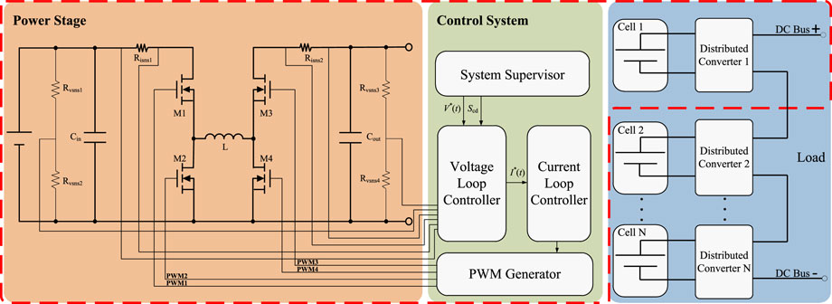
FIGURE 1. System architecture of the active balancing system with “cells decoupled and converters serial-connected.”
Bidirectional DC/DC conversion between the cell port and DC bus port of the smart cell is accomplished by the power stage of a synchronous 4-switch bidirectional buck–boost DC/DC converter; its main circuit structure is shown in the yellow background area of Figure 1, where four switching FETs, M1 to M4, and only one power inductor, L, is utilized. By utilizing the abovementioned structure, bidirectional power conversion between the cell port and DC bus port is achievable, both in the buck and boost modes.
As shown in the green background area of Figure 1, to ensure the stability, accuracy, and dynamic characteristics of the output voltage of the 4-switch bidirectional buck–boost DC/DC converter, a capacitor voltage and an inductor current dual closed loop feedback control system are designed, where proportional–integral–differential (PID) control in the outer loop is utilized to realize output voltage control, with kpv, kiv, and kdv as the corresponding proportional, integral, and differential coefficients, respectively, while in the inner loop, PID control is used to improve the transient response of the converter, with kpi, kii, and kdi as the corresponding proportional, integral, and differential coefficients, respectively. In Figure 1, the inner loop is responsible for sensing the actual current and then accordingly generating a PWM pulse to achieve current regulation, while the outer loop is responsible for sensing the battery cell port voltage, Vcell, and DC bus port voltage, Vout, and then sending current demand I∗ to the current loop to achieve voltage regulation (Xu and Xu, 2013). Moreover, the system supervisor of the smart cell controls the charging/discharging mode switch signal Scd. Communication between each smart cell is accomplished by the system supervisor through the CAN bus, and then, each smart cell shares the cell voltage, charge voltage, and SOC information. The parameter description utilized in this article is listed in 11 Acronyms and Abbreviations.
In the discharging mode, the output voltage of each smart cell is adjustable, while current flowing through the DC bus port is dependent on the load for a specific DC bus voltage. The discharging current of the nth cell Incell at t follows the following equation:
where
Equation 1 shows that Incell can be arbitrarily controlled by regulating Vnout(t), regardless of the load current. That is, the cell current is decoupled from the load current by utilizing the smart cell, and the discharge rate of each smart cell can be controlled by regulating the output voltage of the corresponding smart cell. The output voltage for a lower discharge rate is lower, the output voltage for a higher discharge rate is higher, and the discharge/charge rate of each smart cell is proportional to its output voltage.
In the charging mode, the bidirectional buck–boost converter works in the current control mode, where the current of each cell is controlled independently by the current loop controller of each smart cell.
According to the desired DC bus voltage and SOC of every cell, the smart cell is able to regulate the discharge/charge rate of the battery cell for SOC balancing and to simultaneously maintain the desired DC bus voltage in both the discharging and charging modes.
The combined OCV (open circuit voltage) and CC (Coulombic counting) method is utilized for SOC estimation. The real-time
where
In Equation 2, the real-time current
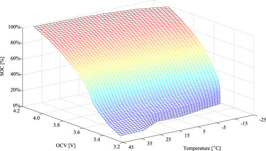
FIGURE 2. Curved surface of the SOC versus temperature and OCV.
As described above, the principle of the active balancing system with “cells decoupled and converters serial-connected” is to independently regulate the discharge/charge rate of each cell. Thus, the primary task is to calculate the discharge or charge rate in real time according the status of each cell.
In the charging mode, to characterize the SOC difference at t, γn(t) is defined as follows:
where SOCn(t) is the real-time SOC of the nth cell at t and
where
where
where Cimax is the acceptable maximum charging current of the battery cell, and Icmin and Icmax are the minimum and maximum charging currents of the smart cell, respectively.
In the discharging mode, Eq. 2 still holds, and now, the adaptive law of ρn(t) is shown in Eq. 7.
where
where
where
where I(t) is the DC bus load current at t and χn(t) is defined as follows:
where
To validate the effectiveness of the proposed dynamic balancing acceleration coefficient adaptive mechanism in charging and discharging modes, experiments were carried out with an experimental setup consisting of six serially connected smart cells, a DC power supply, a programmable DC electronic load, an oscilloscope, a power meter, a USB-CAN adapter, and a monitoring interface implemented on a computer. The photograph of the experimental facility is shown in Figure 3. Each smart cell consisted of four parallel 2,600 mAh LiCoMnNiO2 cells connected in parallel to achieve a higher overall capacity. Detailed information of the abovementioned facilities is listed in Table 1. The bidirectional buck–boost converter was built around Freescale’s 16-bit microcontroller MC9S12XET256, where each smart cell was implemented with an independent converter. The power stage, controller, CAN bus, and peripheral components were integrated in a high-density custom PCB board, as shown in the upper right corner of Figure 3.
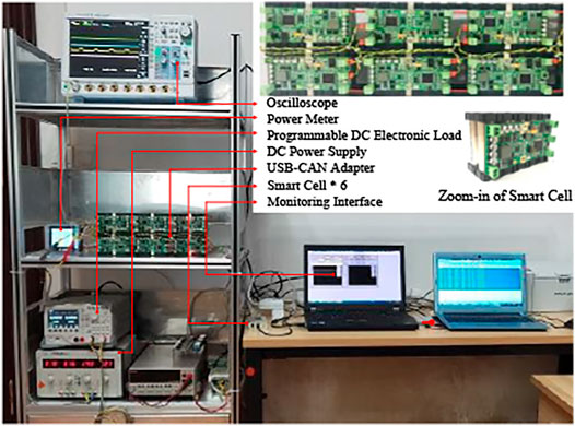
FIGURE 3. Photograph of the experimental facility.
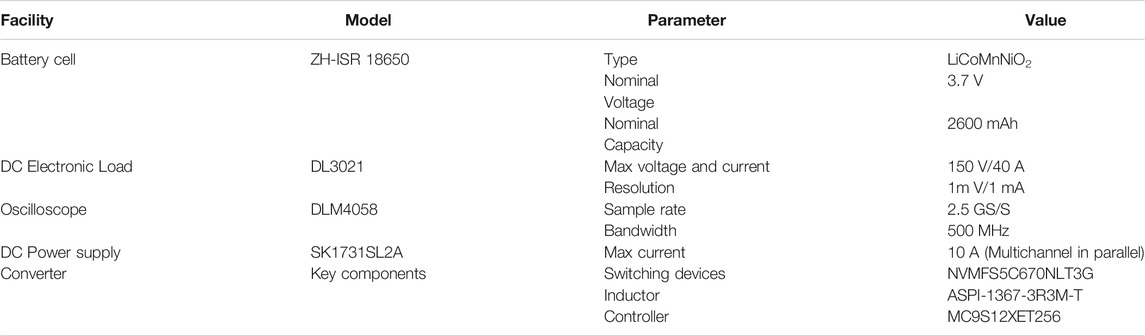
TABLE 1. Experimental facility information.
To demonstrate the effectiveness of the dynamic balancing acceleration coefficient adaptive mechanism in the charging mode, the experimental process in the charging mode is designed as follows.
1) At room temperature of 15°C, six smart cells are charged to the initial states with OCVs ranging from 3.75 to 3.90 V. That is, the SOC ranged from 62.7 to 80.0%.
2) The default charging current is set to
3) The charging cutoff voltage is set to 4.1 V.
4) Adaptive balancing control is enabled in the charging mode. As a comparison, the charge balancing that utilizes the static acceleration coefficient is performed under the same initial condition, where the coefficient is set to 13.3.
The terminal voltages of six cells during the charging process with a static acceleration coefficient and a dynamic acceleration coefficient adaptive mechanism are shown in Figures 4, 5, respectively. The charging process with a static acceleration coefficient lasts 11,717 s, the voltage discrepancy decreases from 150 to 50 mV, and the charging process is terminated when one of the cells reaches the cutoff voltage of 4.1 V. The charging process with a dynamic acceleration coefficient adaptive mechanism takes 7873s to bring cell voltages to the equilibrium state. Figure 6 shows that the acceleration coefficient ρn of six smart cell values is dynamically regulated according to the cell terminal voltages in the charging process.
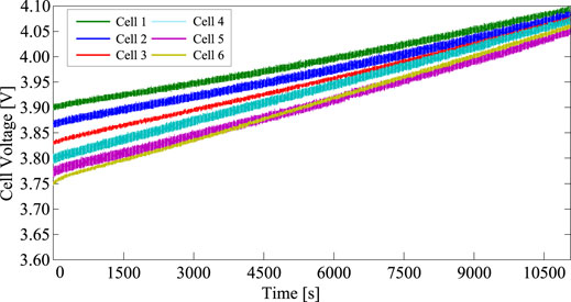
FIGURE 4. Terminal voltages of six cells during the charging process with a static acceleration coefficient.
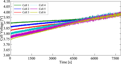
FIGURE 5. Terminal voltages of six cells during the charging process with a dynamic acceleration coefficient adaptive mechanism.
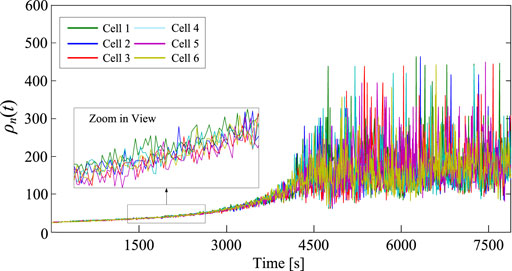
FIGURE 6. Dynamic acceleration coefficient in the charging process.
The maximum voltage deviation between cells is recorded in periods of 1 s during the charging process. The charging process with a static acceleration coefficient takes 10,405 s to decrease the voltage discrepancy from the initial value of 150–30 mV, while the charging process with a dynamic acceleration coefficient adaptive mechanism takes only 3,860 s, as shown in Figures 7, 8 respectively. Furthermore, Figure 8 shows that the charging process with a dynamic acceleration coefficient adaptive mechanism takes only 4,600 s to decrease the voltage discrepancy to 30 mV, and the final voltage discrepancy is approximately 20 mV.
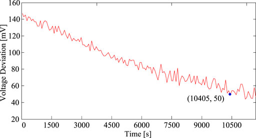
FIGURE 7. Voltage deviation of six cells during the charging process with a static acceleration coefficient.
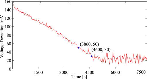
FIGURE 8. Voltage deviation of six cells during the charging process with a dynamic acceleration coefficient adaptive mechanism.
In the discharging mode, the following experimental processes are designed.
1) At room temperature of 15°C, six smart cells are charged to the initial states with OCVs ranging from 3.77 to 3.95 V, that is, the SOC ranged from 63.9 to 83.8%.
2) The discharging cutoff voltage is set to 3.5 V.
3) The DC electric load is set to 30-Ω constant resistant loading mode, and the DC bus voltage of the smart cell pack is set to Vbus = 30 V.
4) Adaptive balancing control is enabled in the discharging mode. Similarly, the discharge balancing operation that utilizes a static acceleration coefficient is performed under the same initial condition.
The terminal voltages of six cells during the discharging processes with a static acceleration coefficient and a dynamic acceleration coefficient adaptive mechanism are shown in Figures 9, 10, respectively. The discharging process with a static acceleration coefficient lasts 6,820 s, and the voltage discrepancy reduced from 180 to 30 mV. The discharging process with a dynamic acceleration coefficient adaptive mechanism lasts 5,800 s. The acceleration coefficient ρn values of six smart cells are shown in Figure 11.
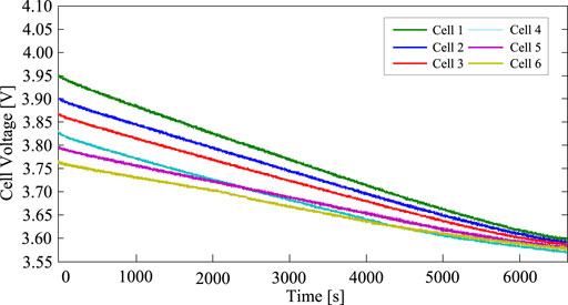
FIGURE 9. Terminal voltages of six cells during the discharging process with a static acceleration coefficient.
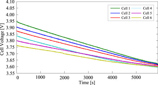
FIGURE 10. Terminal voltages of six cells during the discharging process with a dynamic acceleration coefficient adaptive mechanism.
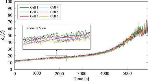
FIGURE 11. Dynamic acceleration coefficient in the discharging process.
In Figures 12, 13, the discharging process with a static acceleration coefficient takes 5,560 s to decrease the voltage discrepancy from the initial 180–50 mV, and the final balancing accuracy is 28 mV, while the discharging process with a dynamic acceleration coefficient adaptive mechanism takes only 4,880 s. Furthermore, Figure 13 shows that the discharging process with a dynamic acceleration coefficient adaptive mechanism takes 5,640 s to decrease the voltage discrepancy to 30 mV, and the final voltage discrepancy is approximately 29 mV. For the DC bus voltage fluctuation during the discharging process shown in Figures 12, 13, the maximum deviation between the set value and actual value is 0.25 V for the static acceleration coefficient and 0.5 V for the dynamic acceleration coefficient adaptive mechanism.
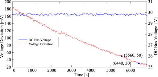
FIGURE 12. Voltage deviation of six cells and DC bus voltage during the discharging process with a static acceleration coefficient.
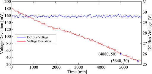
FIGURE 13. Voltage deviation of six cells and DC bus voltage during the discharging process with a dynamic acceleration coefficient adaptive mechanism.
By dynamically regulating the balancing acceleration coefficient of each cell according to the voltage deviation, the adaptive balancing control of cell voltage in charging and discharging modes is proposed for the active balancing system with “cells decoupled and converters serial connected.” The effectiveness of the proposed method for achieving the adaptive balancing control of cell voltage in the charging/discharging mode can be summarized as follows:
1) In both charging and discharging modes, the active balancing speed is effectively accelerated. The proposed dynamic acceleration coefficient adaptive mechanism decreases the balancing time from 10405 to 3,860 s in the charging mode and from 5,560 s to 4,880 s in the discharging mode.
2) The balancing accuracy is improved significantly in the charging mode. The proposed dynamic acceleration coefficient adaptive mechanism decreases the maximum cell voltage deviation from 50 to 20 mV in the charging mode. Nevertheless, the dynamic acceleration coefficient adaptive mechanism does not show significant improvements in balancing accuracy in the discharging mode.
The shortcoming of the proposed method for achieving the adaptive balancing control of cell voltage in the charging/discharging mode is that it slightly decreases the voltage stability of the DC bus.
The original contributions presented in the study are included in the article/Supplementary Material; further inquiries can be directed to the corresponding author.
YW contributed to resources and funding acquisition; DL contributed to writing, data analysis, and visualization; YS contributed to conceptualization, methodology, and writing—original draft; YT contributed to editing; YC and JZ contributed to resources and editing.
The authors gratefully acknowledge the support by the National Natural Science Foundation of China (Grant No. 61803345) and the Science and Technology Development Project of Henan Province (No. 202102210303).
Author YT is employed by Rundian Energy Science and Technology Co., Ltd. Authors YC and JZ are employed by Pinggao Group Intelligent Power Technology Co., Ltd.
The remaining authors declare that the research was conducted in the absence of any commercial or financial relationships that could be construed as a potential conflict of interest.
All claims expressed in this article are solely those of the authors and do not necessarily represent those of their affiliated organizations, or those of the publisher, the editors, and the reviewers. Any product that may be evaluated in this article, or claim that may be made by its manufacturer, is not guaranteed or endorsed by the publisher.
kpv, proportional coefficient of voltage loop; kiv, integral coefficient of voltage loop; kdv, differential coefficient of voltage loop; kpi, proportional coefficient of current loop; kii, integral coefficient of current loop; kdi, differential coefficient of current loop; I∗, current demand; Vcell, cell port voltage; Vout, DC bus port voltage; DC/DC, bidirectional buck–boost DC/DC converter; PID, proportional integral derivative control; PWM, pulse width modulation; CAN, controller area network bus; SOC, state of charge.
Babaie, M., Sharifzadeh, M., Kanaan, H. Y., and Al-Haddad, K. (2021). Switching-Based Optimized Sliding-Mode Control for Capacitor Self-Voltage Balancing Operation of Seven-Level PUC Inverter. IEEE Trans. Ind. Electron. 68 (4), 3044–3057. doi:10.1109/tie.2020.2978704
Baronti, F., Roncella, R., and Saletti, R. (2014). Performance Comparison of Active Balancing Techniques for Lithium-Ion Batteries. J. Power Sourc. 267, 603–609. doi:10.1016/j.jpowsour.2014.05.007
Baughman, A. C., and Ferdowsi, M. (2008). Double-tiered Switched-Capacitor Battery Charge Equalization Technique. IEEE Trans. Ind. Electron. 55 (6), 2277–2285. doi:10.1109/tie.2008.918401
Cao, J., Schofield, N., and Emadi, A. (2008). “Battery Balancing Methods: A Comprehensive Review,” in IEEE Vehicle Power & Propulsion Conference (Harbin, China: IEEE). doi:10.1109/vppc.2008.4677669
Daowd, M., Omar, N., Bossche, P. V. D., and Mierlo, J. V. (2011). “Passive and Active Battery Balancing Comparison Based on Matlab Simulation,” in IEEE Vehicle Power & Propulsion Conference (Chicago,USA: IEEE). doi:10.1109/vppc.2011.6043010
Evzelman, M., Ur Rehman, M. M., Hathaway, K., Zane, R., Costinett, D., Maksimovic, D., et al. (2016). Active Balancing System for Electric Vehicles with Incorporated Low-Voltage Bus. IEEE Trans. Power Electron. 31 (11), 7887–7895. doi:10.1109/tpel.2015.2513432
Gallardo-Lozano, J., Romero-Cadaval, E., Milanes-Montero, M. I., and Guerrero-Martinez, M. A. (2014). Battery Equalization Active Methods. J. Power Sourc. 246 (3), 934–949. doi:10.1016/j.jpowsour.2013.08.026
Gong, Z., van de Ven, B. A. C., Gupta, K. M., da Silva, C., Amon, C. H., Bergveld, H. J., et al. (2020). Distributed Control of Active Cell Balancing and Low-Voltage Bus Regulation in Electric Vehicles Using Hierarchical Model-Predictive Control. IEEE Trans. Ind. Electron. 67 (12), 10464–10473. doi:10.1109/tie.2019.2956396
Hsieh, Y. C., Moo, C. S., Tsai, I. S., and Cheng, J. C. (2002). “Dynamic Charge Equalization for Series-Connected Batteries,” in IEEE International Conference on Industrial Technology (Bankok, Thailand: IEEE).
Huang, W., and Abu Qahouq, J. A. (2015). Energy Sharing Control Scheme for State-Of-Charge Balancing of Distributed Battery Energy Storage System. IEEE Trans. Ind. Electron. 62 (5), 2764–2776. doi:10.1109/tie.2014.2363817
Lambert, F. (2017). Tesla Model 3: Exclusive First Look at Tesla’s New Battery Pack Architecture. Available at: https://electrek.co/2017/08/24/tesla model 3 exclusive battery pack architecture/.
Ma, Y., Duan, P., Sun, Y., and Chen, H. (2018). Equalization of Lithium-Ion Battery Pack Based on Fuzzy Logic Control in Electric Vehicle. IEEE Trans. Ind. Electron. 65 (8), 6762–6771. doi:10.1109/tie.2018.2795578
Ma, Y., Xiao, J., Lin, H., and Wang, Z. (2021). A Novel Battery Integration Method of Modular Multilevel Converter with Battery Energy Storage System for Capacitor Voltage Ripple Reduction. IEEE Trans. Ind. Electron. 68 (12), 12250–12261. doi:10.1109/tie.2020.3044780
Omariba, Z. B., Zhang, L., and Sun, D. (2019). Review of Battery Cell Balancing Methodologies for Optimizing Battery Pack Performance in Electric Vehicles. IEEE Access 7, 129335–129352. doi:10.1109/access.2019.2940090
Ouyang, Q., Chen, J., Zheng, J., and Fang, H. (2018). Optimal Cell-To-Cell Balancing Topology Design for Serially Connected Lithium-Ion Battery Packs. IEEE Trans. Sustain. Energ. 9 (1), 350–360. doi:10.1109/tste.2017.2733342
Pinto, C., Barreras, J. V., Schaltz, E., and Rui, E. A. (2016). Evaluation of Advanced Control for Li-Ion Battery Balancing Systems Using Convex Optimization. IEEE Trans. Sust. Energ. 7 (4), 1. doi:10.1109/tste.2016.2600501
Shan, Y., Hu, J., Chan, K. W., Fu, Q., and Guerrero, J. M. (2019). Model Predictive Control of Bidirectional DC-DC Converters and AC/DC Interlinking Converters-A New Control Method for PV-Wind-Battery Microgrids. IEEE Trans. Sustain. Energ. 10 (4), 1823–1833. doi:10.1109/tste.2018.2873390
Shibata, H., Taniguchi, S., Adachi, K., Yamasaki, K., Ariyoshi, G., Kawata, K., et al. (2001). “Management of Serially- Connected Battery System Using Multiple Switches” in IEEE International Conference on Power Electronics & Drive Systems. (Indonesia: DenpasarIEEE).
Shousha, M., Mcrae, T., Prodic, A., Marten, V., and Milios, J. (2017). Design and Implementation of High Power Density Assisting Step-Up Converter with Integrated Battery Balancing Feature. IEEE J. Emerg. Sel. Top. Power Electron. 5 (3), 1068–1077. doi:10.1109/jestpe.2017.2665340
Tang, X., Zou, C., Wik, T., Yao, K., Xia, Y., Wang, Y., et al. (2019). Run-to-run Control for Active Balancing of Lithium Iron Phosphate Battery Packs. IEEE Trans. Power Elect. 35 (2), 1499–1512.
Tavakoli, A., Khajehoddin, S. A., and Salmon, J. (2019). A Modular Battery Voltage Balancing System Using a Series Connected Topology. IEEE Trans. Power Elect.
Trimboli, M. S., de Souza, A. K., and Xavier, M. A. (2022). Stability and Control Analysis for Series-Input/Parallel-Output Cell Balancing System for Electric Vehicle Battery Packs. IEEE Control. Syst. Lett. 6, 1388–1393. doi:10.1109/lcsys.2021.3097875
Xu, S., Wang, J., and Xu, J. (2013). A Current Decoupling Parallel Control Strategy of Single-phase Inverter with Voltage and Current Dual Closed-Loop Feedback. IEEE Trans. Ind. Electron. 60 (4), 1306–1313. doi:10.1109/tie.2011.2161660
Ye, Y., and Cheng, K. W. E. (2017). Analysis and Design of Zero-Current Switching Switched-Capacitor Cell Balancing Circuit for Series-Connected Battery/supercapacitor. IEEE Trans. Vehicular Tech. 67 (2), 948–955.
Ye, Y., and Cheng, K. W. E. (2015). Modeling and Analysis of Series-Parallel Switched-Capacitor Voltage Equalizer for Battery/Supercapacitor Strings. IEEE J. Emerg. Sel. Top. Power Electron. 3 (4), 977–983. doi:10.1109/jestpe.2015.2418339
Yu, Y., Saasaa, R., Khan, A. A., and Eberle, W. (2019). A Series Resonant Energy Storage Cell Voltage Balancing Circuit. IEEE J. Emerging Selected Top. Power Elect.
Zhang, C., Shang, Y., Li, Z., and Cui, N. (2017). An Interleaved Equalization Architecture with Self-Learning Fuzzy Logic Control for Series-Connected Battery Strings. IEEE Trans. Veh. Technol. 66 (12), 10923–10934. doi:10.1109/tvt.2017.2737401
Zhang, H., Wang, Y., Qi, H., and Zhang, J. (2019). Active Battery Equalization Method Based on Redundant Battery for Electric Vehicles. IEEE Trans. Veh. Technol. 68 (8), 7531–7543. doi:10.1109/tvt.2019.2925742
Keywords: energy storage system, adaptive balancing control, acceleration coefficient, cell voltage discrepancy, charging/discharging
Citation: Wang Y, Liu D, Shen Y, Tang Y, Chen Y and Zhang J (2022) Adaptive Balancing Control of Cell Voltage in the Charging/Discharging Mode for Battery Energy Storage Systems. Front. Energy Res. 10:794191. doi: 10.3389/fenrg.2022.794191
Received: 13 October 2021; Accepted: 03 January 2022;
Published: 07 February 2022.
Edited by:
Yan Xu, Nanyang Technological University, SingaporeReviewed by:
Jichao Hong, University of Science and Technology Beijing, ChinaCopyright © 2022 Wang, Liu, Shen, Tang, Chen and Zhang. This is an open-access article distributed under the terms of the Creative Commons Attribution License (CC BY). The use, distribution or reproduction in other forums is permitted, provided the original author(s) and the copyright owner(s) are credited and that the original publication in this journal is cited, in accordance with accepted academic practice. No use, distribution or reproduction is permitted which does not comply with these terms.
*Correspondence: Yongpeng Shen, c2hlbnlvbmdwZW5nQHp6dWxpLmVkdS5jbg==
Disclaimer: All claims expressed in this article are solely those of the authors and do not necessarily represent those of their affiliated organizations, or those of the publisher, the editors and the reviewers. Any product that may be evaluated in this article or claim that may be made by its manufacturer is not guaranteed or endorsed by the publisher.
Research integrity at Frontiers
Learn more about the work of our research integrity team to safeguard the quality of each article we publish.