 Yan Li
 Guoqiang Tong
 Bin Zhao2
 Kotaro Tagawa
94% of researchers rate our articles as excellent or good
Learn more about the work of our research integrity team to safeguard the quality of each article we publish.
Find out more
ORIGINAL RESEARCH article
Front. Energy Res., 12 April 2022
Sec. Wind Energy
Volume 10 - 2022 | https://doi.org/10.3389/fenrg.2022.790777
This article is part of the Research TopicAerodynamic Upgrades of Wind Turbines and Wind FarmsView all 5 articles
The self-starting performance and aerodynamic characteristics at low wind speeds are the two main problems for the straight-bladed vertical Axis wind turbine (SB-VAWT). In this study, a new kind of wind-gathering device (WGD), which can be installed up and down the rotor, with a polyline hexagonal pyramid shape, was proposed. Both the numerical simulation and the wind tunnel test were performed on this WGD. Based on the method of quadratic rotary orthogonal combination design, the effect of the main structural parameters of the WGD on the self-starting performance of the SB-VAWT was researched by 3D numerical simulation. The optimal combination of the main structural parameters for the WGD under the condition of this study was obtained. Furthermore, wind tunnel tests were carried out on the SB-VAWT with and without the WGD having the optimal structural parameters, including the starting performance, power performance, and rotational revolution performance. The results showed that both the static performance and dynamic performance of the SB-VAWT were increased to some degree by installing this kind of WGD. The improvement is more obvious under the condition of low wind speed. This research can be a useful reference for the in-depth study on the optimal WGDs for the SB-VAWTs.
Vertical axis wind turbines (VAWTs) have recently gained significant interest in the wind energy community (Bangga et al., 2020; Hand and Cashman, 2020). Researchers found that VAWTs are more appropriate for urban applications where unsteady winds are prevalent than horizontal axis wind turbines (HAWTs) (Danao et al., 2014). The straight-bladed vertical axis wind turbine (SB-VAWT), a typical deformation of the Darrieus-type VAWTs, is widely researched and used in the small-scale wind power market (Alexander and Santhanakrishnan, 2020; Bundi et al., 2020; Su H et al., 2020). However, besides some advantages of the unique shape, low noise, and wind direction independence, compared with HAWTs, there are also two main problems for the SB-VAWTs. One is the self-starting performance, and the other is the dynamic characteristics, especially at low wind speeds and low rotational revolutions, because the effective windward area of VAWTs is smaller (Paraschivoiu, 2002).
The numerical simulation and wind tunnel test are the two main methods for the study on the aerodynamic performance of the SB-VAWTs (Abu-Hamdeh and Almitani, 2017; Elkhoury et al., 2018; Rezaeiha et al., 2018a; Song et al., 2018). Researchers have tried two main ways to solve the two problems, i.e., developing the suitable blade airfoil and improving the rotor structure (Rezaeiha et al., 2018b; Nguyen et al., 2019; Rezaeiha et al., 2019a). Jie Su et al. (2020) proposed a kind of VAWT with a V-shaped blade, which could improve the power performance and alleviate the lateral load. Zhu et al. (2020) proposed the VAWT with the flow-deflecting-gap blade, which improved the dynamic stall and increased the torque coefficient to improve the self-starting performance. Researchers also proposed the VAWT with the spiral blade, serrated blade, and dynamic shape through blade deformation technology, which could improve the self-starting performance and the dynamic characteristics (Wang and Zhuang, 2017; Wang et al., 2018; Baghdadi et al., 2020). Li et al. (2018) also proposed a kind of method of installing blade by eccentric that could improve the self-starting performance. All these methods have made great progress in improving the performance of the SB-VAWTs. However, they either raise the difficulty of blade machining or put higher requirements on the structural strength of SB-VAWT.
The effect of auxiliary devices added on the rotor structure of the SB-VAWTs is also used for aerodynamic performance improvement. Researchers have pointed out the effect of the drag wind-cup on the self-starting performance of the SB-VAWTs is effective (Altan and Atı lgan, 2008). However, the drag wind-cup affects the output power characteristics of the SB-VAWT. Other researchers (Wong et al., 2018; Manganhar et al., 2019; Tian et al., 2019; Jiang et al., 2020; Xu et al., 2020) set up guide vanes around the rotor of the SB-VAWTs that could improve the starting performance at different azimuth angles. However, the increased thrust against wind and the large occupied area of the rotor are the main problems. In 2018, Li et al. (2018) proposed a kind of wind-gathering device (WGD) with a truncated cone shape, which can be installed up and down the rotor. Both the WGD and guide vanes could control flow around the rotor. However, the WGD will not need to make space along the wind direction so that the whole rotor structure will not suffer huge thrust and drag force, which is the biggest difference from the guide vanes researched in the past. Also, both the static performance and dynamic performance have been improved to some degree. Based on this idea, we further investigated improving the structure of this kind of WGD.
In this study, the polyline hexagonal pyramid-shaped WGD is proposed, as shown in Figure 1. The function of the hexagonal pyramid shape of WGD is to gather more wind and increase wind speed into the rotor. The polyline shape is designed to improve the flow separation at the upper edge of WGD. The studied parameters of the WGD included the upper edge radius (R) and the distance from the rotor to WGD (ΔL). Based on the quadratic rotary orthogonal combination design method, the effect of the two parameters of WGD on the average starting torque of SB-VAWT was studied by 3D numerical simulation. An optimal combination of structural parameters for the WGD was obtained, and the structural parameters of polyline shape were obtained by analyzing the flow fields. Furthermore, wind tunnel tests were carried out on the SB-VAWT with and without the WGD having the optimal structural parameters, including the starting performance, power performance, and rotational revolution performance. The performance effects of the WGD on SB-VAWT were analyzed and discussed. This research can be a useful reference for the in-depth study on the optimal WGDs for the SB-VAWTs.
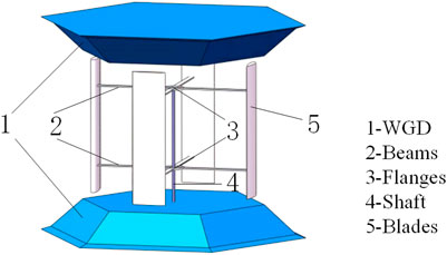
FIGURE 1. Concept of the polyline hexagonal pyramid-shaped WGD.
The wind gathering theory of WGD is simple. Based on the continuity equation of incompressible tube flow shown in Eq. 1, the average wind velocity at the entrance of the rotor tip (U2) can be increased based on the area change of the flow tube. Since the torque and power of the wind turbine are proportional to the square and cube of the wind speed, respectively, both the torque performance and power performance of the SB-VAWT with WGD will be improved to some degree.
In this study, two kinds of WGD were considered, the truncated-cone-shaped WGD and the hexagonal pyramid-shaped WGD. However, the phenomenon of wind flowing around the surface of the truncated cone is a problem that can be thought of as energy loss. Therefore, the hexagonal pyramid-shaped WGD is determined. The function of hexagonal pyramid shape is to gather more wind into the rotor. However, the flow separation at the upper edge of the hexagonal pyramid-shaped WGD was observed based on the CFD, which can also be thought of as flow loss. Based on the acknowledgment of fluid mechanics, flow separation can be improved by reducing the slope of the upper edge of the WGD based on the numerical simulation results. Finally, the WGD with the shape of polyline hexagonal pyramid, as shown in Figure 1, was proposed and researched in this study.
Considering the test section size (1 m*1 m) of the wind tunnel in the laboratory, the SB-VAWT model was selected and designed. The four-bladed SB-VAWT with NACA0018 airfoil with rotor diameter, height, and blade chord length of 0.6, 0.5, and 0.125 m, respectively, was designed. A schematic diagram of the parameters of SB-VAWT is shown in Figure 2. The basic parameters are shown in Supplementary Table S1.
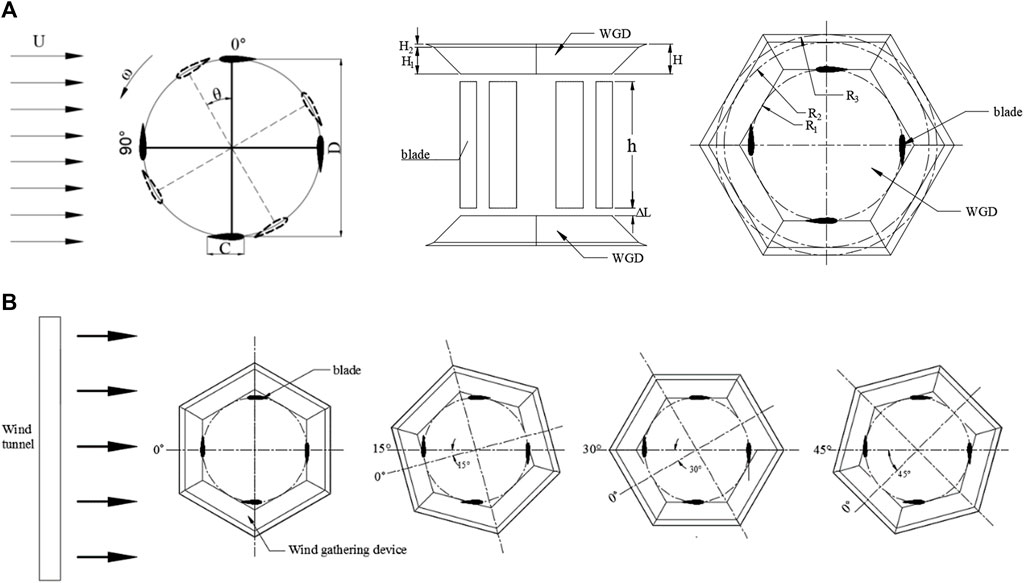
FIGURE 2. Schematic of the WGD and rotor.
A schematic diagram of the parameters of WGD is shown in Figure 2. Based on the previous research results, the height (H) of the WGD is set to 0.12 m, and the radius (R1) of the inscribed circle below the WGD is set to 0.3 m. The inlet angle is determined by the upper edge radius (R) of the WGD. The distance from the rotor to WGD (ΔL) is also a key parameter that affects the effectiveness of the WGD. So, the upper edge radius (R) of the WGD and the distance from the rotor to the WGD (ΔL) are studied as the variables. The optimal combination of structural parameters for the WGD with hexagonal pyramid shape was obtained based on the quadratic rotary orthogonal combination design method. Based on the flow fields of the upper edge of WGD and single-factor experiments, the optimal parameter for polyline shape was obtained. The plane upwind of WGD is identified as the φ = 0° of azimuth angle, taking the counterclockwise rotation as the positive direction of the WGD. Considering the effects of the wind direction on the WGD, four kinds of initial mounting angles are set up, including 0°, 15°, 30°, and 45°, as shown in Figure 2.
The three-dimensional meshing was performed during the numerical simulation, and the mesh data was imported into ANSYS FLUENT. The pressure–velocity coupled SIMPLE method was used. The Reynolds number for the numerical simulation is 1.6×10⁵. The SST k-ω turbulent kinetic energy ratio dissipation rate model was used, which has been widely used in the study of VAWTs, so that computational results and flow separation in the flow field can be obtained (Lam and Peng, 2016; Ghasemian et al., 2017; Rezaeiha et al., 2019b; Wang et al., 2021). The turbulent energy and turbulent dissipation rate adopted the second-order upwind style, and the calculated convergence error was set to 10–6. The time step was set to T/360 for 45 iterations in each time step (Song et al., 2015).
The rotor is placed at the center of the wind tunnel. The direction of inflow is X-axis, and the rotation axis of the rotor is Z-axis. Taking the diameter (D) of the rotor as the standard, the distance of the rotor with inlet and outlet is set as 10D and 15D. The area of the wind tunnel was 20D*20D (Dessoky et al., 2019a). The influence of rotation axis, beams bolts and other structures were ignored during the calculation. The boundary condition of the inlet and outlet were set at velocity inlet and pressure outlet. The velocity of the inlet was set as a constant value of 4 m/s, while the pressure value of the outlet was atmospheric. The surrounding wind tunnel was set as a pressure outlet to avoid affecting the simulation results. The blades and the WGD are set to a no-slip wall. In order to ensure the stability of the grid of the rotation process, the computational domain was divided into static domain and rotation domain. The sliding grid method was adopted of the interface of the computational domain, which could ensure that the grid does not cause deformation during the rotation process. The same grid setup was used for the interface boundary of the static domain and rotation domain to ensure gradient continuity. The grid growth rate is 1.1, and the maximum grid size is set to C with a grid quality of 0.28. As shown in Figure 3, on the blade and WGD surfaces, 30 layers of boundary layer grids were formed, with the first layer cell having a thickness of 3.93 × 10⁻⁵ m to guarantee that Y+ is nearly equal to 1 (Bangga et al., 2020).
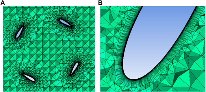
FIGURE 3. Grids around airfoil.
The grid independence was studied because the grids have a greater impact on the results in numerical simulation. The optimal grid parameters were selected considering the accuracy and time spent. The torque coefficients of SB-VAWTs with WGD at 30° azimuth in this study are used to compare the results in steady simulation with different grid numbers. The size of the grid near the blade plays a decisive role in the calculation process, and the external grid has less influence on the calculation results, so the focus is on the grid near the blade. In the grid study, the number of blade section nodes of 100, 170, 240, 310, and 380 and the total number of grids of 5,253,067, 16345876, 27563886, 38645036, and 49034287, are used for comparison, respectively, under all other conditions being the same (Dessoky et al., 2019b). The values simulation result increased with the increase of the grid number when it was less than 38.6 million. When the number of grids exceeded 38.6 million, the values simulation result kept almost the same. The grid number was decided as 38.6 million, considering the accuracy and time spent. A small adjustment was made according to the changes in the shape of WGD, i.e., to increase the number of nodes at the upper edge and the polyline.
In order to verify the validity of the numerical simulation, a wind tunnel test was carried out on the static torque performance of the SB-VAWT without WGD at the wind speed of 4 m/s. The results are shown in Table 1. Both the numerical simulation and the tests are basically the same. Therefore, the simulation results can be used to evaluate the aerodynamic performance of the SB-VAWT to a certain degree. However, the data of simulation is higher than the tests. The two main reasons can be considered. First, the simulation model was simplified so that the shaft, beams, flanges, and bolts were ignored. However, during the wind tunnel tests, these components inevitably affected the overall aerodynamic performance. Second, compared with the stable conditions in the simulation process, the environment was more complicated during the tests, which led to differences in results.
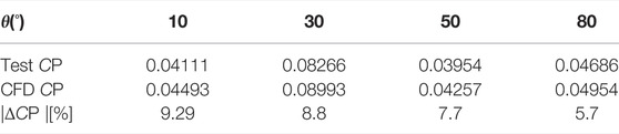
TABLE 1. Validation of numerical simulation.
After obtaining the optimal structural parameters of the WGD by numerical simulation, a real rotor with the optimal WGD was designed and made. Wind tunnel tests were carried out on the starting performance, power performance, and rotational revolutions performance of the SB-VAWT with and without WGD. The wind tunnel tests were conducted by using a low-speed open type one with a test section of 1 m × 1 m, and the turbulence intensity is 5% in Northeast Agricultural University in this study. The test model and parameters of the SB-VAWT and WGD are shown in Supplementary Figure S1 and Supplementary Table 2.
The range of wind speed supplied by the wind tunnel is from 1 m/s to 20 m/s with the ±3% precision. Four kinds of wind speeds, 4 m/s, 5 m/s, 8 m/s, and 10 m/s, were used for the test. An ultrasonic wind rotation sensor (GILL Wind Sonic, England) with ±0.1% precision was used to measure the wind speed of the wind tunnel. The rotor was set up at the center of the wind tunnel outlet and 0.6 m distance from the outlet. A three-phase asynchronous induction motor with brakes (Mitsubishi, Japan) was used to control rotational revolutions by a variable frequency drive, and the rotational revolutions were measured by intelligent digital. A torque meter (ONO SOKKI, Japan) with the ±0.2% precision was used to measure the torque and rotational revolutions of the rotor, which was placed between the rotor and three-phase asynchronous motor.
For the static torque measurements, the rotor axis was fixed by the brake of the induction motor. The static torque was measured at the interval of about 10° of azimuth angle and was averaged for the 60s to obtain the average starting torque Mas. Because there are four blades of the rotor, the rotation period is 90°. Therefore, only the static torque during the azimuth angles from 0° to 90° was measured.
For the measurement of dynamic characteristics, the rotor was operated with a constant rotational revolution under steady wind speeds. The dynamic torque was measured for the 60 s to obtain the average dynamic torque M. The whole dynamic torque characteristics were obtained by changing the conditions of rotational revolutions. The output power coefficient was calculated by using torque coefficients and tip speed ratios. The revolutions were tested under the condition of no loads on the rotor. The variation in rotational revolutions of the rotor from standstill to steady is measured (time not exceeding 600s).
In this study, some performance parameters were used, including starting torque coefficient Cms, power coefficient Cp, and the tip speed ratio λ. The computational formulas are shown as follows:
where Ms is the static torque, (N• m); ρ is the air density, (kg/m3); A is the rotor swept area, (m2); U is the wind speed, (m/s); R is the radius of rotation of the rotor, (m); P is the power, (W); M is the dynamic torque, (N• m); n is the rotational revolutions, (r/min).
Glauert’s method (Glauert, 1933) has been used to correct the data for wind tunnel blockage effects. As shown in Eqs 5-7, uT is the stream-wise velocity through the rotor, and Cm is the torque coefficient. Once U′ is known, the starting torque coefficient (Cm’) and the power coefficient (CP’) can be calculated.
In this study, the rotational revolutions, torque, and wind speed were measured, so the error transmission formula of Cm and Cp could be obtained as shown in Eqs 8, 9:
Among them, Wm, WP, Wn, WM, and WU represent the errors of torque coefficient, power coefficient, rotational revolutions, torque, and wind speed, respectively. According to the above equation, uncertainty values can be obtained. The errors of the ultrasonic wind speed sensor, rotation sensor, torque sensor, power coefficient, and torque coefficient are 3, 0.1, 0.2, 0.632, and 0.422%, respectively, as shown in Supplementary Table S3.
The studied parameters of WGD included the upper edge radius (R) and the distance from the rotor to WGD (ΔL). Based on the quadratic rotary orthogonal combination design method, the nine sets of structural parameter combinations were obtained. The average starting torque (as shown in Eq. 10) of the rotor with different structural parameters WGD was obtained by 3D numerical simulation. Through the analysis of variance on the computational results, the average starting torque as the target, the optimal structural parameters of WGD under the condition of this study were finally obtained.
where Msi is the starting torque at different azimuth angles, and N is the number of Msi.
A total of two factors and five levels were coded for design. Based on the previous research results (Yan et al., 2018), the range of the upper edge radius R (m) was 0.36–0.48m, and the range of the distance ΔL (m) was 0.01–0.04 m. The coding table is shown in Supplementary Table S4.
The average starting torques (Mas) of the rotor with different structural parameters WGD were obtained by simulation, as shown in Table 2. The improvement effect of the parameters combination of the R (m) = 0.42 m and the △L (m) = 0.025 m was optimal, and the Mas is 0.058124 (N•m). The R (m) = 0.3776 m and the △L (m) = 0.0144 m was the slightest effect, and the Mas is 0.0470106 (N• m).

TABLE 2. Tests design table.
According to the tests design results, the response surface was obtained, as shown in Figure 4. Along with the increase of R (m) and △L (m), the torque shows a trend of first rising and then falling, which the optimal R (m) was in the range of 0.415–0.424m, the optimal range of △L (m) was from 0.025 to 0.0303 m. This is because when the upper edge radius was too small, the slope of the WGD section was too large, the stability of the airflow into the rotor and the WGD would be affected. When the radius of the upper edge was too large, i.e., the length of the upper edge was longer, a lot of process loss would be cured of the airflow through into the rotor. When the distance between WGD and rotor was small, the rotor was close to the low-speed area at the bottom edge of the WGD. However, the distance was too large, so the effect of WGD was weakened.

FIGURE 4. Response surface.
The equation was obtained as shown in Eq. 11. The optimal structural parameters of the hexagonal pyramid-shaped WGD were obtained. The R is 0.418m, the R1 is 0.3m, the H is 0.12m, and the ΔL is 0.03 m.
where x1 is the radius of the upper edge-inscribed circle, and x2 is the distance between WGD and rotor.
Figure 5 shows the velocity contours of the WGD. It can be seen from the figure that the flow separation occurs close to the upper edge of the WGD so that the upper edge does not play a role in gathering wind. The distance between the flow separation position and the upper edge is 0.02m, and the cross-sectional-inscribed circle radius is 0.398 m. So, the line shape was optimized to a polyline shape at the separation position, which will improve the phenomenon of flow separation. The separation position had moved to the upper edge of WGD to increase the wind gathering.
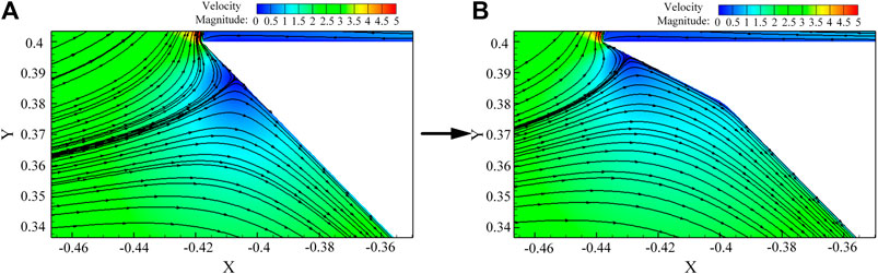
FIGURE 5. Flow at the upper edge of the WGD.
Under the condition of the other WGD parameters keeping unchanged, the upper edge radius of WGD at the distance of 0.02 m was changed. The value range of the change of the upper edge was set from 0.418 to 0.458 m. The interval of the upper edge on numerical simulation was set as 0.01m, which equaled that the angle change was 2°. The Mas of SB-VAWT with WGD with hexagonal pyramid shape was 0.0586. The Mas of SB-VAWT with WGD with polyline shape was 0.059429 when the upper edge radius was 0.438 m. Finally, the optimal upper edge radius was decided as 0.438 m.
Based on the simulation, a WGD with the optimal structural parameters under the condition of this study was obtained. Wind tunnel tests carried out the static torque of the SB-VAWT with and without WGD. Figure 6 shows the results at wind speeds of 4 m/s, 5 m/s, 8 m/s, and 10 m/s.
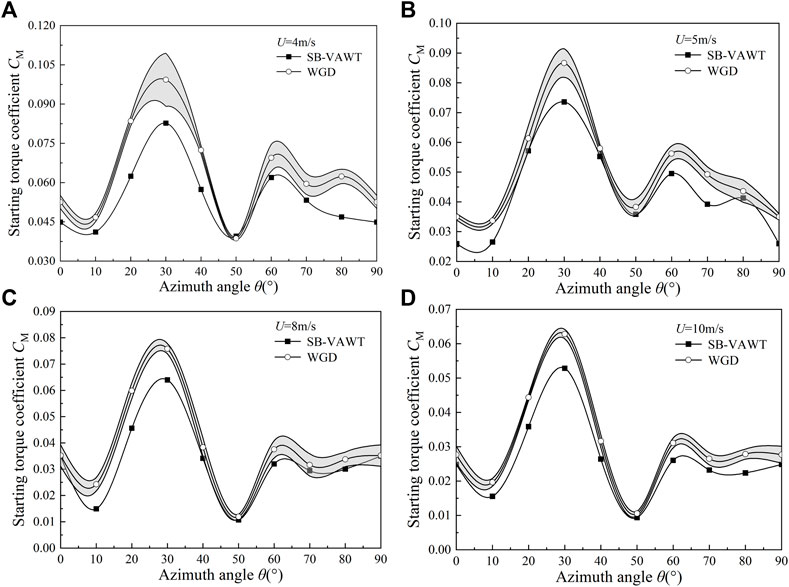
FIGURE 6. Static torque coefficients of the rotor with and without the WGD by wind tunnel tests.
As mentioned in Figure 2 of Section 3.1, there are four kinds of the mounting angle of WGD against wind direction, including 0°, 15°, 30°, and 45°. Wind tunnel tests were carried out under all four conditions. In order to facilitate the result comparison of the rotor without WGD, the test data of the rotor with the WGD at different mounting angles are shown in the shaded region. As shown in Figure 6, the starting torque coefficients of the rotor with WGD have been greatly improved at almost the azimuth angles for all wind speeds. This indicates the effectiveness of the WGD on the starting performance improvement for the SB-VAWT. The best improvement of starting torque coefficient at the azimuth angles of 30°, which the increasing percentage was 34.18, 25.39, 21.95, and 21.67% at the four wind speeds. This indicates that the WGD has a better function on the starting performance of the SB-VAWT at lower wind speeds.
Figure 7 shows the streamline around the rotor with and without WGD at the azimuth angle θ = 30°. According to Figure 7, the disorderly flow field improved when the WGD was installed. More wind flowed into the rotor through WGD. The vortex on the tip of the blade had been weakened, which means that the loss of energy on the tip of the blade had been reduced, and the performance of the upstream blade also will be improved. The vortex near the blades had moved away from the downstream blades, which concentrated on the WGD slope and reduced the downstream drag blades to improve the aerodynamic characteristics of the SB-VAWT.
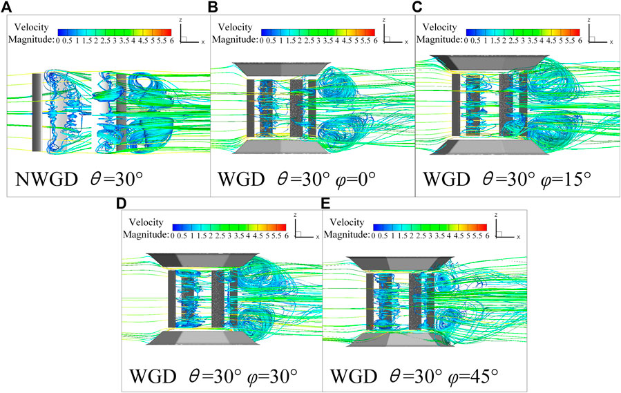
FIGURE 7. Static streamline comparison at θ = 30°.
The schematic diagram of the different cross-sections is shown in Supplementary Figure S2. The center and the top position of the rotor were selected as z = 0 and z1 = 0.25. The mounting angle φ = 15° of the WGD was taken as an example to compare the pressure contours of the rotor with and without WGD at the plane of z and z1, as shown in Figure 8.
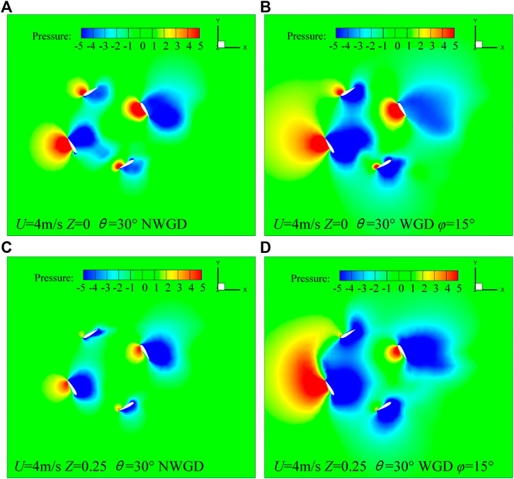
FIGURE 8. Static pressure distribution at θ = 30°.
It can be seen from Figure 8 that the pressure distribution in the z and z1 planes was significantly different for SB-VAWT. The pressure difference on the blades at the z plane was higher than the z1 plane. The aerodynamic force was provided from the middle part of the blade. The loss of energy occurred on the tip of the blades. After WGD was installed, the negative pressure near the blade at the z plane was expanded. At the same time, both of the range of positive and negative pressure in the z1 plane were enlarged. It means that the pressure difference was increased on the blade, and the loss of energy on the tip of the blade was reduced. More energy will be applied by the rotor, which will improve the starting performance of the SB-VAWT significantly.
The velocity distribution diagrams of the rotor with and without WGD in z and z1 planes at azimuth angles of 30° are shown in Figure 9. It can be seen from the figure that the airflow speed through WGD into the SB-VAWT was increased and obvious at the z1 plane. In the wake area, the velocity of the rotor with WGD was lower, which showed that more energy was absorbed by the rotor, causing larger velocity attenuation in the wake. In summary, the installation of WGD has improved the internal flow field. The velocity increase of the airflow into the SB-VAWT and the velocity attenuation of the wake part increased significantly.
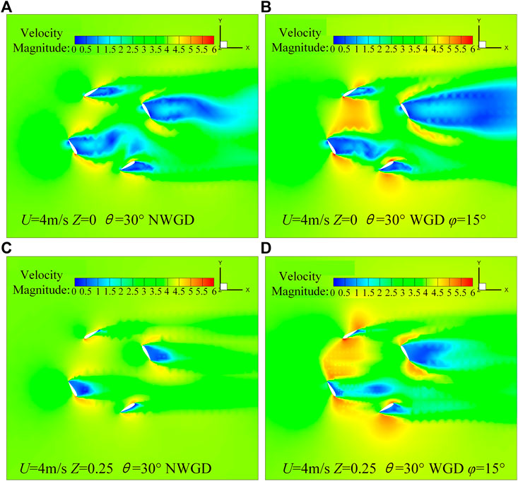
FIGURE 9. Static velocity distribution at θ = 30°.
The power coefficient of the SB-VAWT with and without WGD was obtained by wind tunnel test, as shown in Figure 10. It is the same as the previous data processing method of the static torque coefficient in Section 5.2.1, the test data of the rotor with the WGD at different mounting angles are shown in the shaded region in Figure 10. It can be seen from the figure that the power coefficients of the rotor with the WGD have been improved at almost all wind speeds. For the lower wind speeds condition such as 4 m/s and 5 m/s, the improvement of the power coefficient is significant. Compared with the rotor without WGD, the maximum power coefficient increased by 151.03 and 94.56%, respectively. Furthermore, a different degree of improvement of power coefficient can be found for almost all tip speed ratios. Therefore, it can be said that the WGD can increase the power performance of the SB-VAWT at lower wind speeds. For the higher wind speeds such as 8 m/s and 10 m/s, the improvement of the power coefficients by the WGD can also be found. The maximum power coefficient just increased by 28.02 and 16.07%. This indicates that the WGD can positively affect the power performance improvement at lower wind speeds.
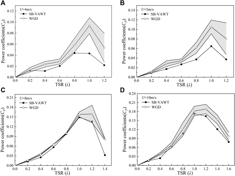
FIGURE 10. Power coefficients of the rotor with and without the WGD by wind tunnel tests.
Figure 11 shows the pressure distribution of the rotor with and without WGD at different cross-sections at a tip speed ratio of 1.0 and azimuth of 0°. According to the figure, both in the z and z1 planes, the pressure difference near the blades was effectively increased when the WGD was installed. This results in increased torque and promotes SB-VAWT rotation, which improves aerodynamic performance.
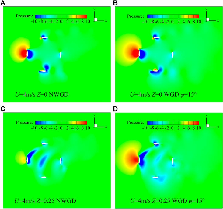
FIGURE 11. Dynamic pressure distribution.
Figure 12 shows the speed distribution at different cross-sections of the rotor with and without WGD at the tip speed ratio of 1.0 and azimuth of 20°. The difference in the high-velocity area of the rotor with and without WGD at the z plane seems inconspicuous. However, at the z1 plane, the overall airflows velocity of the rotor with WGD was increased. The low-velocity area of the wake with WGD was expanded, which means that the rotor absorbed more energy in the airflow. Based on the flow characteristics, the power performance of the rotor with WGD was improved significantly.
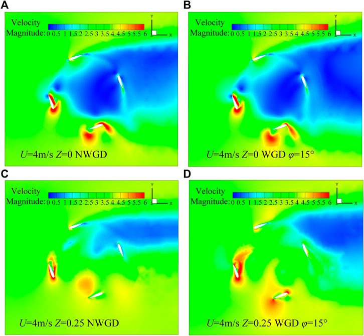
FIGURE 12. Dynamic velocity distribution.
The rotational revolution performance is another important factor to evaluate the dynamic characteristics of the SB-VAWT. Figure 13 shows the rotational revolutions of the rotor with and without WGD at the wind speeds of 4 m/s, 5 m/s, 8 m/s, and 10 m/s. The revolutions were tested under the condition of no loads on the rotor.

FIGURE 13. Rotational revolutions of the rotor with and without the WGD by wind tunnel tests.
According to Figure 13, at the lower wind speed of 4 m/s, the rotor with WGD could self-start while the rotor without WGD could not. This indicates that the WGD can reduce the minimum starting wind speed. In other words, the SB-VAWT can self-start at lower wind speed by using WGD. For the condition of 5 m/s, the rotor with and without WGD could both start rotation. The revolution of the rotor with WGD reached 70 rpm, which was 10 rpm higher than the rotor without WGD. At the higher wind speeds of 8 m/s, the revolution of the rotor with WGD reached 380 rpm, which is 20rpm higher than the rotor without WGD. However, for the wind speed of 10 m/s, the maximum revolutions for the two kinds of rotors were almost the same. These results indicate that with the increase of wind speed, the wind-gathering ability of the WGD becomes weak. In other words, this kind of WGD can have a good function on the rotational revolution performance of the SB-VAWT at lower wind speeds.
In this study, the optimal combination of structural parameters for the WGD with hexagonal pyramid shape was obtained based on the quadratic rotary orthogonal combination design method. The wind tunnel tests on torque characteristics, power characteristics, and rotational revolution characteristics of SB-VAWTs with and without WGD were carried out at wind speeds of 4 m/s, 5 m/s, 6 m/s, and 8 m/s. Finally, the main conclusions are obtained as follows:
(1) A new kind of wind-gathering device for the SB-VAWT with the polyline hexagonal pyramid-shape installed up and down the rotor was proposed. The function of the hexagonal pyramid-shaped WGD is to gather more wind and increase wind speed into the rotor, and the polyline shape is designed to improve the flow separation at the upper edge of the WGD. The effectiveness of the improvement on the aerodynamic characteristics of the SB-VAWT was researched and confirmed by numerical simulations and wind tunnel tests.
(2) Based on the quadratic rotary orthogonal combination design method, two main structural parameters of the WGD, including the upper edge radius and distance to the rotor, were studied by 3D numerical simulation on the static starting torque. The upper edge flow separation position of the WGD was also studied. Considering the maximum average starting toque in one revolution and the static flow field characteristics, the effects of the WGD on the static performance of the SB-VAWT were analyzed. One combination of the optimal structural parameters of the WGD was obtained.
(3) Wind tunnel tests were carried out on the SB-VAWT with and without the WGD having the optimal structural parameters. For the static performance, the static torque coefficients of the SB-VAWT with the WGD were increased at almost the azimuth angles for all test wind speeds. The best improvement of the starting torque coefficient occurred near the azimuth angle of 30°, in which the increasing percentages were 34.18, 25.39, 21.95 and 21.67% at the test wind speeds of 4 m/s, 5 m/s, 8 m/s, and 10 m/s, respectively. The WGD has good effects on the improvement of static torque performance at lower wind speeds and reduces the self-starting wind speed to 4 m/s.
(4) For the dynamic aerodynamic characteristics, by using the WGD, the maximum power coefficient of the SB-VAWT is increased by 151.03, 94.56, 28.02, and 16.07%, respectively, at the test wind speeds of 4 m/s, 5 m/s, 8 m/s, and 10m/. The rotational revolution performance has also improved greatly, especially at lower wind speeds. The effectiveness of the aerodynamic performance improvement of the WGD has been confirmed.
Furthermore, in-depth study research will be carried out for the optimal structure of WGD suitable for more kinds of SB-VAWTs.
The original contributions presented in the study are included in the article/Supplementary Material, further inquiries can be directed to the corresponding author.
YL: conceptualization, methodology, resources, writing—original draft, writing—review and editing, project administration, and funding acquisition. GT: methodology, validation, formal analysis, investigation, data curation, and writing—original draft. BZ: validation, formal analysis, investigation, data curation, and writing—original draft. FF: validation and investigation. KT: validation and investigation.
The authors declare that the research was conducted in the absence of any commercial or financial relationships that could be construed as a potential conflict of interest.
All claims expressed in this article are solely those of the authors and do not necessarily represent those of their affiliated organizations, or those of the publisher, the editors, and the reviewers. Any product that may be evaluated in this article, or claim that may be made by its manufacturer, is not guaranteed or endorsed by the publisher.
The Supplementary Material for this article can be found online at: https://www.frontiersin.org/articles/10.3389/fenrg.2022.790777/full#supplementary-material
Abu-Hamdeh, N. H., and Almitani, K. H. (2017). Construction and Numerical Analysis of a Collapsible Vertical axis Wind Turbine. Energ. Convers. Manage. 151, 400–413. doi:10.1016/j.enconman.2017.09.015
Alexander, A. S., and Santhanakrishnan, A. (2020). Mechanisms of Power Augmentation in Two Side-By-Side Vertical axis Wind Turbines. Renew. Energ. 148, 600–610. doi:10.1016/j.renene.2019.10.149
Altan, B. D., and Atılgan, M. (2008). An Experimental and Numerical Study on the Improvement of the Performance of Savonius Wind Rotor. Energ. Convers. Manage. 49 (12), 3425–3432. doi:10.1016/j.enconman.2008.08.021
Baghdadi, M., Elkoush, S., Akle, B., and Elkhoury, M. (2020). Dynamic Shape Optimization of a Vertical-axis Wind Turbine via Blade Morphing Technique. Renew. Energ. 154, 239–251. doi:10.1016/j.renene.2020.03.015
Bangga, G., Dessoky, A., Wu, Z., Rogowski, K., and Hansen, M. O. L. (2020). Accuracy and Consistency of CFD and Engineering Models for Simulating Vertical axis Wind Turbine Loads. Energy 206, 118087. doi:10.1016/j.energy.2020.118087
Bundi, J. M., Ban, X., Wekesa, D. W., and Ding, S. (2020). Pitch Control of Small H-type Darrieus Vertical axis Wind Turbines Using Advanced Gain Scheduling Techniques. Renew. Energ. 161, 756–765. doi:10.1016/j.renene.2020.05.184
Danao, L. A., Edwards, J., Eboibi, O., and Howell, R. (2014). A Numerical Investigation into the Influence of Unsteady Wind on the Performance and Aerodynamics of a Vertical axis Wind Turbine. Appl. Energ. 116, 111–124. doi:10.1016/j.apenergy.2013.11.045
Dessoky, A., Bangga, G., Lutz, T., and Krämer, E. (2019b). Aerodynamic and Aeroacoustic Performance Assessment of H-Rotor Darrieus VAWT Equipped with Wind-Lens Technology. Energy 175, 76–97. doi:10.1016/j.energy.2019.03.066
Dessoky, A., Lutz, T., Bangga, G., and Krämer, E. (2019a). Computational Studies on Darrieus VAWT Noise Mechanisms Employing a High Order DDES Model. Renew. Energ. 143, 404–425. doi:10.1016/j.renene.2019.04.133
Elkhoury, M., Kiwata, T., Nagao, K., Kono, T., and ElHajj, F. (2018). Wind Tunnel Experiments and Delayed Detached Eddy Simulation of a Three-Bladed Micro Vertical axis Wind Turbine. Renew. Energ. 129, 63–74. doi:10.1016/j.renene.2018.05.096
Ghasemian, M., Ashrafi, Z. N., and Sedaghat, A. (2017). A Review on Computational Fluid Dynamic Simulation Techniques for Darrieus Vertical axis Wind Turbines. Energ. Convers. Manage. 149, 87–100. doi:10.1016/j.enconman.2017.07.016
Glauert, H. (1933). Wind Tunnel Interference on Wings, Bodies and Airscrews. London: H.M. Stationery Office.
Hand, B., and Cashman, A. (2020). A Review on the Historical Development of the Lift-type Vertical axis Wind Turbine: From Onshore to Offshore Floating Application. Sustainable Energ. Tech. Assessments 38, 100646. doi:10.1016/j.seta.2020.100646
Jiang, Y., Zhao, P., Stoesser, T., Wang, K., and Zou, L. (2020). Experimental and Numerical Investigation of Twin Vertical axis Wind Turbines with a Deflector. Energ. Convers. Manage. 209, 112588. doi:10.1016/j.enconman.2020.112588
Lam, H. F., and Peng, H. Y. (2016). Study of Wake Characteristics of a Vertical axis Wind Turbine by Two- and Three-Dimensional Computational Fluid Dynamics Simulations. Renew. Energ. 90, 386–398. doi:10.1016/j.renene.2016.01.011
Li, Y., Zhao, S., Tagawa, K., and Feng, F. (2018). Starting Performance Effect of a Truncated-Cone-Shaped Wind Gathering Device on Small-Scale Straight-Bladed Vertical axis Wind Turbine. Energ. Convers. Manage. 167, 70–80. doi:10.1016/j.enconman.2018.04.062
Manganhar, A. L., Rajpar, A. H., Luhur, M. R., Samo, S. R., and Manganhar, M. (2019). Performance Analysis of a Savonius Vertical axis Wind Turbine Integrated with Wind Accelerating and Guiding Rotor House. Renew. Energ. 136, 512–520. doi:10.1016/j.renene.2018.12.124
Nguyen, V.-D., Jansson, J., Goude, A., and Hoffman, J. (2019). Direct Finite Element Simulation of the Turbulent Flow Past a Vertical axis Wind Turbine. Renew. Energ. 135, 238–247. doi:10.1016/j.renene.2018.11.098
Paraschivoiu, I. (2002). Wind Turbine Design: With Emphasis on Darrieus Concept. Montréal, QC: Presses Internationales Polytechnique.
Rezaeiha, A., Montazeri, H., and Blocken, B. (2019a). CFD Analysis of Dynamic Stall on Vertical axis Wind Turbines Using Scale-Adaptive Simulation (SAS): Comparison against URANS and Hybrid RANS/LES. Energ. Convers. Manage. 196, 1282–1298. doi:10.1016/j.enconman.2019.06.081
Rezaeiha, A., Montazeri, H., and Blocken, B. (2018a). Characterization of Aerodynamic Performance of Vertical axis Wind Turbines: Impact of Operational Parameters. Energ. Convers. Manage. 169, 45–77. doi:10.1016/j.enconman.2018.05.042
Rezaeiha, A., Montazeri, H., and Blocken, B. (2019b). On the Accuracy of Turbulence Models for CFD Simulations of Vertical axis Wind Turbines. Energy 180, 838–857. doi:10.1016/j.energy.2019.05.053
Rezaeiha, A., Montazeri, H., and Blocken, B. (2018b). Towards Accurate CFD Simulations of Vertical axis Wind Turbines at Different Tip Speed Ratios and Solidities: Guidelines for Azimuthal Increment, Domain Size and Convergence. Energ. Convers. Manage. 156, 301–316. doi:10.1016/j.enconman.2017.11.026
Song, C., Zhao, Z., and Wu, G. (2018). Effect of Wind Speed and Airfoil Camber on Aerodynamic Performance of Vertical axis Wind Turbines[J]. J. Drainage Irrigation Machinery Eng. 36 (03), 243–249. (In Chinese). doi:10.3969/j.issn.1674-8530.17.3006
Song, C., Zheng, Y., Zhao, Z., Zhang, Y., Li, C., and Jiang, H. (2015). Investigation of Meshing Strategies and Turbulence Models of Computational Fluid Dynamics Simulations of Vertical axis Wind Turbines. J. Renew. Sustain. Energ. 7 (3), 033111. doi:10.1063/1.4921578
Su, H., Dou, B., Qu, T., Zeng, P., and Lei, L. (2020). Experimental Investigation of a Novel Vertical axis Wind Turbine with Pitching and Self-Starting Function. Energ. Convers. Manage. 217, 113012. doi:10.1016/j.enconman.2020.113012
Su, J., Chen, Y., Han, Z., Zhou, D., Bao, Y., and Zhao, Y. (2020). Investigation of V-Shaped Blade for the Performance Improvement of Vertical axis Wind Turbines. Appl. Energ. 260, 114326. doi:10.1016/j.apenergy.2019.114326
Tian, W., Mao, Z., and Ding, H. (2019). Numerical Study of a Passive-Pitch Shield for the Efficiency Improvement of Vertical axis Wind Turbines. Energ. Convers. Manage. 183, 732–745. doi:10.1016/j.enconman.2019.01.006
Wang, P., Liu, Q., Li, C., Miao, W., Luo, S., Sun, K., et al. (2021). Effect of Trailing Edge Dual Synthesis Jets Actuator on Aerodynamic Characteristics of a Straight-Bladed Vertical Axis Wind Turbine. Energy 238, 121792. doi:10.1016/j.energy.2021.121792
Wang, Z., Wang, Y., and Zhuang, M. (2018). Improvement of the Aerodynamic Performance of Vertical axis Wind Turbines with Leading-Edge Serrations and Helical Blades Using CFD and Taguchi Method. Energ. Convers. Manage. 177, 107–121. doi:10.1016/j.enconman.2018.09.028
Wang, Z., and Zhuang, M. (2017). Leading-edge Serrations for Performance Improvement on a Vertical-axis Wind Turbine at Low Tip-Speed-Ratios. Appl. Energ. 208, 1184–1197. doi:10.1016/j.apenergy.2017.09.034
Wong, K. H., Chong, W. T., Sukiman, N. L., Shiah, Y.-C., Poh, S. C., Sopian, K., et al. (2018). Experimental and Simulation Investigation into the Effects of a Flat Plate Deflector on Vertical axis Wind Turbine. Energ. Convers. Manage. 160, 109–125. doi:10.1016/j.enconman.2018.01.029
Xu, W., Li, G., Wang, F., and Li, Y. (2020). High-resolution Numerical Investigation into the Effects of Winglet on the Aerodynamic Performance for a Three-Dimensional Vertical axis Wind Turbine. Energ. Convers. Manage. 205, 112333. doi:10.1016/j.enconman.2019.112333
Yan, L. I., Zhicheng, W. U., and Kotaro, T. (2018). Numerical Simulation on Aerodynamic Characteristics of Vertical axis Wind Turbine with Eccentric Rotor Structure[J]. J. Drainage Irrigation Machinery Eng. 36 (05), 413–419. (In Chinese). doi:10.3969/j.issn.1674-8530.17.0023
Zhu, H., Hao, W., Li, C., and Ding, Q. (2020). Effect of Flow-Deflecting-gap Blade on Aerodynamic Characteristic of Vertical axis Wind Turbines. Renew. Energ. 158, 370–387. doi:10.1016/j.renene.2020.05.092
Acronyms
HAWT Horizontal axis wind turbine
VAWT Vertical axis wind turbine
Symbols
Cp Power coefficient
Cms Starting torque coefficient
Mas Average static torque coefficient
Ms Starting torque
λ Tip speed ratio
N Number of blades
D Rotor diameter
h Height of blade
C Blade chord
φ Mounting angle of WGD
ρ Air density
U′ Corrected wind speed
CP’ Corrected power coefficient
WP Error of power coefficient
WM Error of torque
SB-VAWT Straight-bladed vertical axis wind turbine
WGD Wind-gathering device
ΔL Distance to wind turbine
R1 Bottom-inscribed circle radius of WGD
R2 Polyline-inscribed circle radius of WGD
R3 Upper-inscribed circle radius of WGD
H Height of WGD
H1 Height between polyline and bottom edge
H2 Height between polyline and upper edge
U Wind speed
θ Azimuth angle of the rotor against wind
P Power
uT The stream-wise velocity through the rotor
Cm’ Corrected torque coefficient
Wm Error of torque coefficient
Wn Error of rotational revolutions
WU Error of wind speed
Keywords: straight-bladed vertical axis wind turbine, wind-gathering device, polyline hexagonal pyramid shape, aerodynamic performance, numerical simulation, wind tunnel test
Citation: Li Y, Tong G, Zhao B, Feng F and Tagawa K (2022) Study on Aerodynamic Performance of a Straight-Bladed VAWT Using a Wind-Gathering Device With Polyline Hexagonal Pyramid Shape. Front. Energy Res. 10:790777. doi: 10.3389/fenrg.2022.790777
Received: 07 October 2021; Accepted: 15 March 2022;
Published: 12 April 2022.
Edited by:
Francesco Castellani, University of Perugia, ItalyReviewed by:
Galih Bangga, University of Stuttgart, GermanyCopyright © 2022 Li, Tong, Zhao, Feng and Tagawa. This is an open-access article distributed under the terms of the Creative Commons Attribution License (CC BY). The use, distribution or reproduction in other forums is permitted, provided the original author(s) and the copyright owner(s) are credited and that the original publication in this journal is cited, in accordance with accepted academic practice. No use, distribution or reproduction is permitted which does not comply with these terms.
*Correspondence: Yan Li, bGl5YW5uZWF1QDE2My5jb20=
Disclaimer: All claims expressed in this article are solely those of the authors and do not necessarily represent those of their affiliated organizations, or those of the publisher, the editors and the reviewers. Any product that may be evaluated in this article or claim that may be made by its manufacturer is not guaranteed or endorsed by the publisher.
Research integrity at Frontiers
Learn more about the work of our research integrity team to safeguard the quality of each article we publish.