
94% of researchers rate our articles as excellent or good
Learn more about the work of our research integrity team to safeguard the quality of each article we publish.
Find out more
ORIGINAL RESEARCH article
Front. Energy Res. , 31 January 2022
Sec. Solar Energy
Volume 10 - 2022 | https://doi.org/10.3389/fenrg.2022.778024
This article is part of the Research Topic System Level Optimization Techniques for Solar Energy Technologies View all 6 articles
In order to decrease the performance effect of a single string in part of a photovoltaic (PV) array and increase the adaptive PV power generation, independent multiple series-connected PV strings are usually adopted in PV system projects to implement the input configuration. Besides, the conversion circuits with multipath inputs are required to be designed for the corresponding inverters to carry out the control algorithms. Since independent and parallel-connected modes exist for the PV string input in actual engineering projects, it is of great significance to effectively identify different PV inputs automatically for inverter inputs. In order to solve the problems of high hardware circuit requirements and complicated control algorithms in most of the existing control methods, a multiple PV string input type recognition method is proposed. Through the proposed software control algorithm, to realize automatically, accurately and quickly identify the external input connection type of the different photovoltaic strings under the external condition changes. The proposed method is free from increasing the inverter hardware cost, and it enhances the capability of identification and judgment. Moreover, experiments and engineering applications are implemented to verify the proposed control method.
As a kind of renewable energy, photovoltaic (PV) power generation is widely used. In the medium- and small-scale distributed PV application engineering projects, parallel-connected multiple PV arrays or independent inputs are usually adopted for the purpose of reducing the effects on the power generation of the whole system caused by faults of a single component/PV array or shading. Therefore, the systems with multiple PV array inputs become the hot points of research and applications (Wen et al., 2019); the grid integration technologies of photovoltaic power plants were introduced and discussed (Panigrahi et al., 2020), and the power conversion and control technologies of the distributed power generation system were summarized and analyzed (Blaabjerg et al., 2017). It can be concluded that from common photovoltaic power generation systems and related technologies, by adopting the systems of multipath PV inputs, the input-side component configuration of a PV array can be optimized. Meanwhile, requirements are raised for the DC input side of the connected PV inverter as the corresponding connecting circuits and terminals are required to match it.
The main input connecting modes for multipath PV arrays include the parallel-connected and independent modes. In different distributed PV power generation engineering projects, the connections that are not in use exist. In addition, different connection modes need to be identified for the control and operation of the input-side conversion circuit for connecting the inverter. However, the existing application research mainly focuses on the conversion circuit control and maximum power point tracking (MPPT) control. For example, the study by Jiang et al., (2013) investigated a type of multi-input PV Solar System and designed the corresponding conversion circuit and control algorithms. In the study by Tian et al. (2019), a kind of multi-input converter (MIC) was proposed for an independent PV system to satisfy the application of multiple PV array inputs. A type of multi-input single-output PV system was proposed in the study by ELhagry et al., (2016), which is made of multiple PV modules, and each module supplies power to the DC-DC converter. It can be seen that the existing research activities mostly carry out the investigations on conversion circuit topologies and the corresponding control methods with the premise of knowing that the PV array is with the multi-input connection mode.
In actual PV engineering projects, the input connection modes of multiple PV arrays can be either parallel-connected or independent, in which case the corresponding connected inverter needs to have the automatic mode identification function. Therefore, according to the technical requirements of mode identification for the input modes of multiple PV arrays, an automatic identification algorithm is proposed, and it is verified by experiments to effectively satisfy the application requirements of different PV engineering applications.
As an important format of the PV system, distributed PV power generation systems are being widely used in industrial and commercial roofs, which becomes the main solution to the future PV system applications.
The system consists of PV components, inverters, and loads (power grid), as shown in Figure 1. Usually multiple PV components are parallel-connected to be PV arrays (Mirhosseini et al., 2015; Zakzouk et al., 2017; Zhang and Ruan, 2019; Pardhi et al., 2020).
Different component array composition modes are adopted according to the scales of PV stations at the power generation terminals of distributed PV systems. The main composition types are shown in Figure 2.
It can be seen that the component connection modes at the PV power generation terminal can be divided into central, parallel, and independent connection modes, as shown in Figure 3. The central connection mode is displayed in Figure 3A, which is usually used to realize single-input system integration. For a parallel-connected PV array, the common terminals of input sides can be connected together, which is shown in Figure 3B, and the PV array is derived by connecting the single PV strings. Figure 3C displays the independent connection mode, where the PV strings connect to each other individually, and the common terminals are separated.
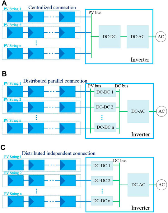
FIGURE 3. PV string connection types: (A) central connection, (B) parallel connection, and (C) independent connection.
In the regular PV component array configuration process (Gonzalez et al., 2007; Abdalla et al., 2013; Mirhosseini et al., 2015; Sochor and Akagi, 2016; Zakzouk et al., 2017; Zhang and Ruan, 2019; Abe et al., 2020; Pardhi et al., 2020), when the connection mode in Figure 3A is adopted, if one panel is faulty or shaded, the power is affected, then reducing the benefits of power generation and reliability.
By using the multi-string input mode, the deficiency of the independent connection mode can be avoided. Each string is connected to the DC-DC converter for the control purpose, therefore ensuring the high-efficiency power generation and reducing the effects brought by shadings, and it becomes the new trend of research and application of distributed PV power generation (Chen et al., 2007; Gonzalez et al., 2007; Fortunato et al., 2008; Veerachary, 2008; Soleimani et al., 2012; Abdalla et al., 2013; Rosli et al., 2014a; Rosli et al., 2014b; Haghighian and Hosseini, 2015; Moon et al., 2015; Tampubolon et al., 2015; Sochor and Akagi, 2016; Chander and Kumar, 2017; Abe et al., 2020; Bodele and Kulkarni, 2020; Mao et al., 2020; Zhang and Jiang, 2020; Ahmed et al., 2021). However, the existing research and applications mainly focus on circuit topologies and maximum power point tracking (MPPT) control algorithms, which are based on the fact that the connection mode is known in advance. While in real PV system engineering projects, there are various connection modes, in which case the control algorithms for identifying the input connection mode of PV strings need to be investigated and designed.
For a distributed PV system application, the PV strings can be parallel-connected or connected to the corresponding DC-DC converter circuits independently, as shown in Figure 4.
The DC-DC converter connected to each group of PV strings is usually a boost converter, which realizes the MPPT control for increasing the array input voltage. For the strings in the array that are connected to the converters in actual engineering projects, the converters are required to be equipped with the capability of automatically identifying the connection mode (parallel/independent-connected input) of the PV array terminal.
For the regular control method, when the PV inverter has multipath PV inputs, the judgment of the PV string input mode is realized when the machine starts. One of the DC-DC conversion circuits is selected to increase the PV voltage, with the other paths remaining standstill. By identifying the voltage difference between the path with the increased PV voltage and the other paths and comparing it with the threshold value, the input mode of the PV array can be determined.
However, in actual applications, when the machine starts, the input PV power in each path is relatively high, especially for the parallel-connected input mode. Improving the PV voltage will result in the fact that the PV power works in the path with the increased PV voltage, in which case a higher bearing capacity is needed for the corresponding hardware in this path, increasing the hardware cost. Besides, erroneous judgment may be induced because of the low power caused by the low illumination intensity.
Therefore, a novel and high-efficiency multipath PV string input mode identification control method is proposed in this study. The proposed method has low hardware requirements for the circuit hardware, and only the software modification is required to realize the mode identification.
The proposed type recognition method can implement the identification actions in the following three stages: before the inverter starts, after the inverter starts, and during the working process.
The details of the proposed method are shown in Figure 5, including the following:
a) The initialization stage, before the PV inverter is powered on and loaded.
b) The start-up stage, pre-set the input mode, then recognize.
c) The operation stage, during the normal working process of the PV inverter, through the closed-loop PI adjusting PWM control signals of the converters by setting the same reference currents
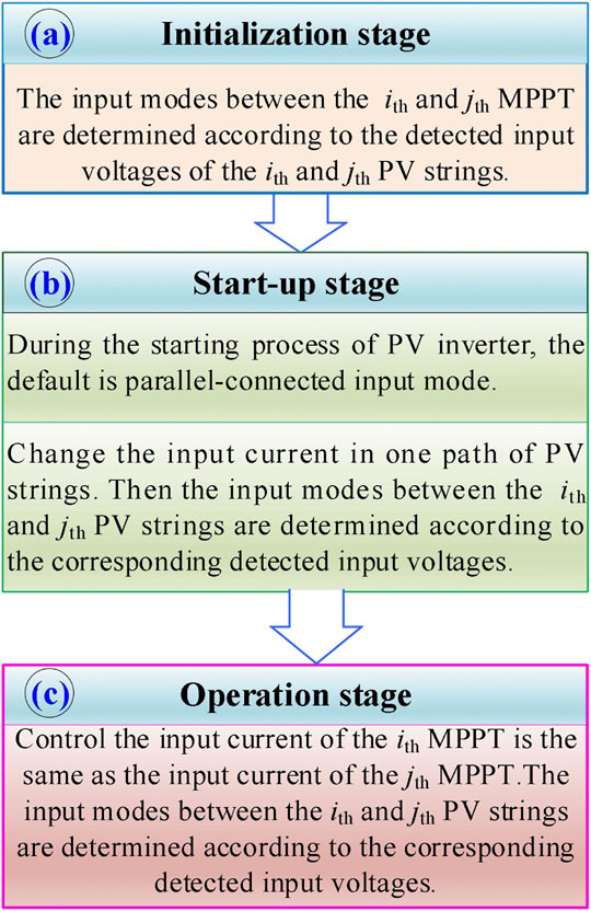
FIGURE 5. Proposed type recognition control method. (A) Initialization stage, (B) Start-up stage, and (C) Operation stage.
Since the default is the parallel-connected input mode at the starting stage of the PV inverter, the input current in one path is not changed until the power becomes stable. Therefore, the issue of requiring a higher power bearing capacity for the hardware of the PV string path with the increased voltage in the high-voltage high-load condition at the starting stage. The effect of not requiring the hardware cost increment with the default of the parallel-connected input mode starting in the high-voltage condition can be realized.
Moreover, when the solar illumination intensity is low, since the input mode judgment is still based on the real-time input voltages of the ith and jth strings after the PV inverter starts, the erroneous recognition caused by the low illumination intensity can be avoided.
The flowchart of the proposed recognition control method is displayed in Figure 6, and the detailed steps are as follows:
i) Collect the real-time input voltages and currents in n strings, where n > 1 and n is a positive integer.
ii) Calculate the input voltage
iii) Before the PV inverter is powered on, the input modes between the ith and jth PV strings are determined according to the corresponding detected input voltages at present. Calculate the first difference
iv) Determine the relationship between the absolute value of the first difference and set threshold
As shown in Figure 7, when the absolute value of the first difference is larger than the set threshold, the two PV strings are regarded as independent, which means that two different PV strings input independently, and the judgment is over.
v) When the absolute value of the first difference is smaller than the set threshold, the input mode judgment is implemented after the PV inverter is powered on and loaded.
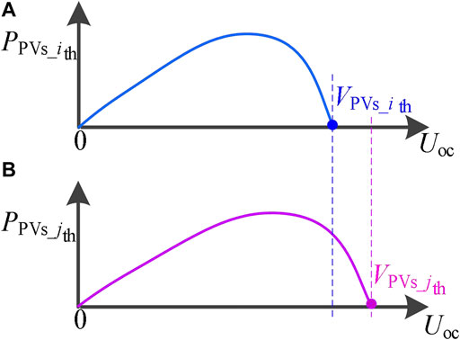
FIGURE 7. PV power generation curves in the independent connection type: (A). The power generation curve of the ith PV string; (B) The power generation curve of the jth PV string.
The corresponding power–voltage curves are shown in Figure 8, the curves of independent PV strings with the same voltage are shown in Figures 8A,B, or the parallel-connected input mode is shown in Figure 8C.
vi) If the absolute value of the first difference is smaller than the set threshold, then the two PV strings are determined to be in the parallel-connected input mode. After the PV inverter is powered on, the input mode will be further judged.
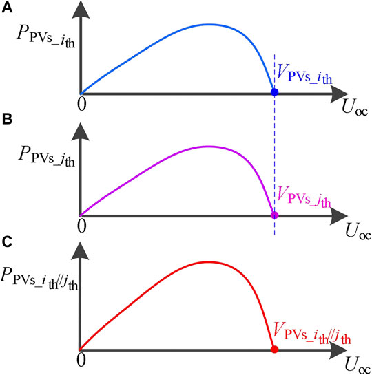
FIGURE 8. PV power generation curves in the independent or parallel-connected types: (A) The power generation curve of the ith PV string; (B) The power generation curve of the jth PV string; (C) The power generation curve of ith and jth PV parallel strings.
When the variation of power
vii) When the variation of power is smaller than the predetermined power threshold value, it means the power is stable. In real engineering applications, the input current change can be controlled by adjusting the reference set current. If the inputs more than two PV strings are judged, the reference currents should be set to be different from each other when controlling the currents to adjust.
viii) Calculate the second difference value between the input voltages of the ith and jth PV strings in real time.
ix) When the absolute value of second difference
In actual application engineering projects, the system starts in the parallel-connected input mode. After the power is stable, the bus voltage is kept higher than the largest predetermined value among all input voltages. By changing the reference current in one PV string, it is attempted to expand the difference between the input voltages in the two PV strings. The power–voltage curves before and after changing the input current are shown in Figure 9.
x) When the absolute value of the second difference is smaller than the second set threshold, it can be determined that the input modes of the ith and jth PV strings are the parallel-connected ones.
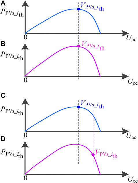
FIGURE 9. Changes of input current PV power generation variation curves: (A) The power generation curve of the ith PV string; (B) The power generation curve of the jth PV string; (C) The power generation curve of the ith PV string with current
In the normal operation stage, the input currents of the ith and jth PV strings are controlled to be the same. The reference currents are used to control the actual input currents. When the reference currents are set to be the same, the actual input currents will output according to the reference currents.
xi) Calculate the third difference value between the input voltages of the ith and jth PV strings in real time.
xii)When the absolute value of the third difference is less than the set threshold value, the input modes of the ith and jth PV strings are kept in the parallel-connected ones.
When the absolute value of the third difference
If the absolute value of the third difference is larger than the third set threshold, it indicates that a relatively large voltage difference is presented between the two PV strings. Since the input voltage between the two PV strings is monitored in real time, once a relatively large voltage difference occurs, the input mode is switched to the independent ones. Then, the program executes the corresponding control algorithm according to the determined input type recognition.
The experimental verification is implemented for the proposed control algorithm. The dual-input string inverter is adopted to carry out the identification control experiment. The schematic diagram of the inverter experiment platform is shown in Figure 10.
The widely used two-level circuit topology structure is applied (Du et al., 2015). A boost converter is adopted for the preceding stage to realize the improvement of the input PV voltage and MPPT control, and an H6 inverter circuit is adopted to output the AC power (Zhang et al., 2014; Hendawi, 2019).
The experiment platform is displayed in Figure 11. The PV input is simulated by the two PV programmable power supplies at the PV string side. The experimental waveforms are derived for different working conditions.
According to the actual photovoltaic power station installation data and engineering experience values, to select and preset the difference of voltage and power parameters. The preset threshold voltage and power values are shown in Table 1.
Test 1. Simulated Independent PV Input I
Through the control software of the PV programmable DC power supply, the test 1 parameters of the two PV input strings are shown in Figure 12. Figure 12A is the PV parameters of the first PV string, and Figure 12B is the PV parameters of the second PV string.
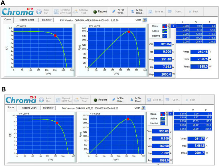
FIGURE 12. Simulating the independent input mode experimental condition I: (A) Input working parameters for PV string 1 and (B) Input working parameters for PV string 2.
The input voltages of different PV strings are simulated as shown in Figure 12. It can be seen the measured input voltages of PV strings VPVs_1 and VPVs_2 are 250.15 and 261.17 V, respectively, and the voltage difference between them is 11.02 V, which is larger than the first voltage difference threshold 8 V. Therefore, the input mode is determined to be independent.
The waveforms of the measured working voltages and currents in the two PV strings are displayed in Figure 13. After the input mode is determined to be independent, their corresponding DC-DC converters operate independently after t1. At t2, the independent MPPT tracking control is realized.
Test 2. Simulated Independent PV Input II
Through the control software of the PV programmable DC power supply, the test 2 parameters of the two PV string outputs are set, as shown in Figure 14. The parameters of the first PV string are displayed in Figure 14A, and the parameters of the second PV string are displayed in Figure 14B.
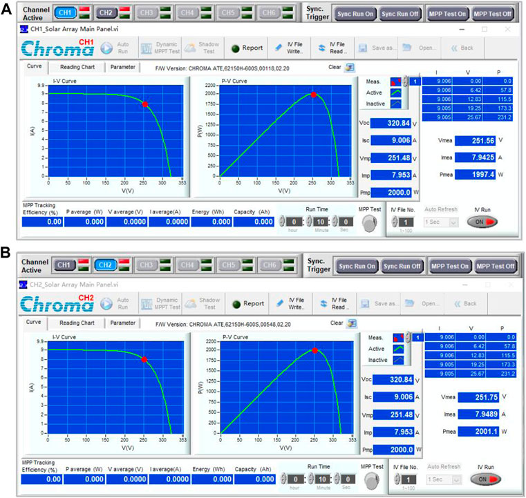
FIGURE 14. Simulating the independent input mode experimental condition II: (A) Input working parameters of PV string 1 and (B) Input working parameters of PV string 2.
The input voltages of different PV strings are simulated as shown in Figure 14. It can be seen the measured input voltages of PV strings VPVs_1 and VPVs_2 are 251.56 and 251.75 V, respectively, and the voltage difference between them is 0.19 V, which is smaller than the first voltage difference threshold 8 V. Therefore, the input mode is determined to be parallel-connected.
The measured experimental waveforms are shown in Figure 15. The working current IPVs_2 is changed at t1. Then, the measured voltage difference between VPVs_1 and VPVs_2 is 27.5 V, which is larger than the second voltage difference threshold 8 V. The input mode is determined to be independent.
Test 3. Simulated PV Parallel-Connected Input
Through the control software of the PV programmable DC power supply, the test 3 parameters of the two PV strings are shown in Figure 16.
The experimental waveforms at different stages are shown in Figure 17, and the test waveforms at the power-on stage are shown in Figure 17A. Since a single simulated PV power supply is adopted for the parallel-connected input, the difference between the measured voltage values at the input sides is smaller than the second set threshold VPVset_2. Then, move on to the identification control at the normal working stage, and the experimental waveforms are shown in Figure 17B. Two current reference values of the two paths are set to be the same, and the difference between the measured voltage values of the two paths is smaller than the third set threshold VPVset_3; then, the input mode is determined to be parallel-connected.
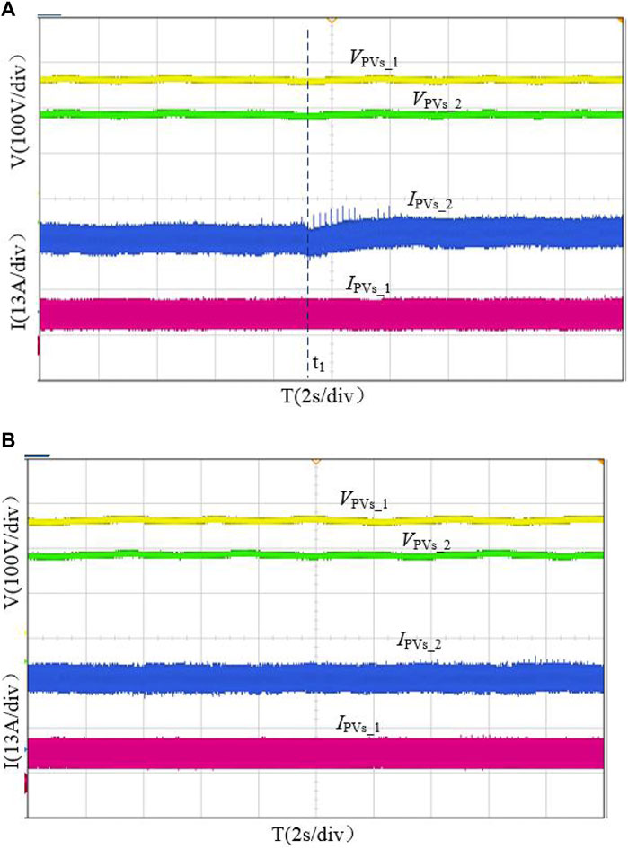
FIGURE 17. Experimental waveforms of the parallel-connected input mode: (A) at the starting stage and (B) at the normal working stage.
It can be seen from the experimental results that the proposed hierarchical identification control method completes different determination algorithms at the initial power-on, starting, and working stages. The proposed algorithm has low hardware requirements, and the dynamic identification can be achieved through software programming. Therefore, the improper working issue of inverters due to erroneous judgment for different connection modes can be avoided, which enhances inverters’ adaptability and reliability.
For the purpose of reducing the effects caused by using a single input PV string, the multipath PV string input mode is usually adopted. In practice, the input mode of the PV string connecting to the inverter at the DC input terminal needs to be judged. In address to the need of identifying the independent and parallel-connected modes of PV strings, a novel and advanced identification control method is proposed. Through the hierarchical identification control algorithms at the initial power-on, starting, and operation stages, the accurate multiple photovoltaic string input type recognition can be effectively realized:
• Compared with the conventional control algorithm, the proposed method solves the problem of the high hardware cost by the default parallel-connected input startup at high-voltage output scenarios.
• In the case of weak illumination intensity, the input mode is recognized according to the input voltage of different PV strings in real time, to improve the accuracy of type recognition.
• By adopting the proposed control method software, without upgrading the inverter hardware configuration, it can meet the diversity requirements of various photovoltaic string engineering applications.
The original contributions presented in the study are included in the article/Supplementary Material, further inquiries can be directed to the corresponding author.
All authors listed have made a substantial, direct, and intellectual contribution to the work and approved it for publication.
This work was supported in part by the project of the Jiangsu Overseas Research and Training Program for the University, the Qinlan Project of Jiangsu Province, the Specialty Leading Person Advanced Study and Training Project of Jiangsu Higher Vocational Colleges, the Science and Technology Project of Jiangsu Province Construction System, the Science and Technology Planning Project of Suzhou City, and the Collaborative Innovation Center and Industry-University-Research Base Construction Project of Suzhou Vocational University.
Author YZ was employed by Jiangsu Renac Power Technology Co., Ltd. Author XC was employed by Wuxi Solartale PV Technology Co., Ltd. Author YW was employed through technical Industry-University-Research Cooperation with CQC Intime Testing Technology Co., Ltd.
The remaining authors declare that the research was conducted in the absence of any commercial or financial relationships that could be construed as a potential conflict of interest.
All claims expressed in this article are solely those of the authors and do not necessarily represent those of their affiliated organizations, or those of the publisher, the editors, and the reviewers. Any product that may be evaluated in this article, or claim that may be made by its manufacturer, is not guaranteed or endorsed by the publisher.
Abdalla, I., Corda, J., and Zhang, L. (2013). Multilevel DC-Link Inverter and Control Algorithm to Overcome the PV Partial Shading. IEEE Trans. Power Electron. 28 (1), 14–18. doi:10.1109/tpel.2012.2209460
Abe, C. F., Dias, J. B., Notton, G., and Poggi, P. (2020). Computing Solar Irradiance and Average Temperature of Photovoltaic Modules from the Maximum Power Point Coordinates. IEEE J. Photovoltaics 10 (2), 655–663. doi:10.1109/jphotov.2020.2966362
Ahmed, R. M., Zakzouk, N. E., Abdelkader, M. I., and Abdelsalam, A. K. (2021). Modified Partial-Shading-Tolerant Multi-Input-Single-Output Photovoltaic String Converter. IEEE Access 9, 30663–30676. doi:10.1109/access.2021.3058695
Blaabjerg, F., Yang, Y., Yang, D., and Wang, X. (2017). Distributed Power-Generation Systems and Protection. Proc. IEEE 105 (7), 311–1331. doi:10.1109/jproc.2017.2696878
Bodele, N., and Kulkarni, P. S. (2020). “A Multi-Input Hybrid Converter for Small Off-Grid Solar Photo-Voltaic System,” in IEEE First International Conference on Smart Technologies for Power, Energy and Control (STPEC), Nagpur, India, 25-26 Sept. 2020, 1–6. doi:10.1109/stpec49749.2020.9297747
Chander, H., and Kumar, L. (2017). “Multiple Input Converter for Standalone Photovoltaic Applications,” in 14th IEEE India Council International Conference (INDICON), Roorkee, India, 15-17 Dec. 2017, 1–6. doi:10.1109/INDICON.2017.8488110
Chen, Y.-M., Liu, Y.-C., Hung, S.-C., and Cheng, C.-S. (2007). Multi-Input Inverter for Grid-Connected Hybrid PV/Wind Power System. IEEE Trans. Power Electron. 22 (3), 1070–1077. doi:10.1109/tpel.2007.897117
Du, Y., Lu, D. D.-C., Chu, G. M. L., and Xiao, W. (2015). Closed-Form Solution of Time-Varying Model and its Applications for Output Current Harmonics in Two-Stage PV Inverter. IEEE Trans. Sustain. Energ. 6 (1), 142–150. doi:10.1109/tste.2014.2360616
ELhagry, M. M., Elkady, Z., Abdel-Rahim, N., and Bendary, F. (2016). New Topology of Multiple-Input Single-Output PV System for DC Load Applications. J. Electr. Syst. Inf. Technol. 3 (3), 471–484. doi:10.1016/j.jesit.2015.10.005
Fortunato, M., Giustiniani, A., Petrone, G., Spagnuolo, G., and Vitelli, M. (2008). Maximum Power Point Tracking in a One-Cycle-Controlled Single-Stage Photovoltaic Inverter. IEEE Trans. Ind. Electron. 55 (7), 2684–2693. doi:10.1109/tie.2008.918463
Gonzalez, R., Lopez, J., Sanchis, P., and Marroyo, L. (2007). Transformerless Inverter for Single-phase Photovoltaic Systems. IEEE Trans. Power Electron. 22 (2), 693–697. doi:10.1109/tpel.2007.892120
Haghighian, S. K., and Hosseini, S. H. (2015). “A Novel Multi-Input DC/DC Converter with a General Power Management Strategy for Grid Connected Hybrid PV/FC/battery System,” in The 6th Power Electronics, Drive Systems & Technologies Conference (PEDSTC2015), Tehran, Iran, 3-4 Feb. 2015, 1–6. doi:10.1109/pedstc.2015.7093240
Hendawi, E. (2019). “Analysis, Simulation and Comparison between H6 Transformer-Less Inverter Topologies,” in 21st International Middle East Power Systems Conference (MEPCON), Cairo, Egypt, 17-19 Dec. 2019, 220–225. doi:10.1109/mepcon47431.2019.9007922
Jiang, Y., Qahouq, J. A. A., Orabi, M., and Youssef, M. (2013). “PV Solar System with Multiple Input Power Converter Operating in Discontinous Conduction Mode and MPPT Control,” in Intelec.35th International Telecommunications Energy Conference, SMART POWER AND EFFICIENCY, Hamburg, Germany, 13-17 Oct. 2013, 1–5.
Mao, M., Cui, L., Zhang, Q., Guo, K., Zhou, L., and Huang, H. (2020). Classification and Summarization of Solar Photovoltaic MPPT Techniques: A Review Based on Traditional and Intelligent Control Strategies. Energ. Rep. 6, 1312–1327. doi:10.1016/j.egyr.2020.05.013
Mirhosseini, M., Pou, J., and Agelidis, V. G. (2015). Single- and Two-Stage Inverter-Based Grid-Connected Photovoltaic Power Plants with Ride-Through Capability under Grid Faults. IEEE Trans. Sustain. Energ. 6 (3), 1150–1159. doi:10.1109/tste.2014.2347044
Moon, S., Yoon, S.-G., and Park, J.-H. (2015). A New Low-Cost Centralized MPPT Controller System for Multiply Distributed Photovoltaic Power Conditioning Modules. IEEE Trans. Smart Grid 6 (6), 2649–2658. doi:10.1109/tsg.2015.2439037
Panigrahi, R., Mishra, S. K., Srivastava, S. C., Srivastava, A. K., and Schulz, N. N. (2020). Grid Integration of Small-Scale Photovoltaic Systems in Secondary Distribution Network-A Review. IEEE Trans. Ind. Applicat. 56 (3), 3178–3195. doi:10.1109/tia.2020.2979789
Pardhi, P. K., Sharma, S. K., and Chandra, A. (2020). Control of Single-phase Solar Photovoltaic Supply System. IEEE Trans. Ind. Applicat. 56 (6), 7132–7144. doi:10.1109/tia.2020.3024171
Rosli, M. A., Yahaya, N. Z., and Baharudin, Z. (2014). “A Multi-Input Converter for Hybrid Photovoltaic Array/wind Turbine/fuel Cell and Battery Storage System Connected AC Grid Network,” in IEEE Innovative Smart Grid Technologies - Asia (ISGT ASIA), Kuala Lumpur, Malaysia, 20-23 May 2014, 25–30. doi:10.1109/isgt-asia.2014.6873758
Rosli, M. A., Yahaya, N. Z., and Baharudin, Z. (2014). “Multi-input DC-DC Converter for Hybrid Renewable Energy Generation System,” in IEEE Conference on Energy Conversion (CENCON), Johor Bahru, Malaysia, 13-14 Oct. 2014, 283–286. doi:10.1109/cencon.2014.6967516
Sochor, P., and Akagi, H. (2016). Theoretical Comparison in Energy-Balancing Capability between Star- and Delta-Configured Modular Multilevel Cascade Inverters for Utility-Scale Photovoltaic Systems. IEEE Trans. Power Electron. 31 (3), 1980–1992. doi:10.1109/tpel.2015.2442261
Soleimani, H., Dastfan, A., and Hajizade, A. (2012). “DC Bus Voltage Control by Using a Multi Input/output System of Photovoltaic/battery,” in 2012 IEEE International Conference on Power Electronics, Drives and Energy Systems (PEDES), Bengaluru, India, 16-19 Dec. 2012, 1–5. doi:10.1109/pedes.2012.6484291
Tampubolon, M., Purnama, I., Chi, P., Lin, J., Hsieh, Y., and Chiu, H. (2015). “A DSP-Based Differential Boost Inverter with Maximum Power point Tracking,” in 9th International Conference on Power Electronics and ECCE Asia (ICPE-ECCE Asia), Seoul, Korea (South), 1-5 June 2015, 309–314. doi:10.1109/icpe.2015.7167802
Tian, Q., Zhou, G., Leng, M., Fan, X., and Yan, T. (2019). “A Novel Dual-Input Dual-Output Converter and Dynamic Energy Management for PV/Battery Systems,” in IEEE Energy Conversion Congress and Exposition (ECCE), Baltimore, MD, USA, 29 Sept.-3 Oct. 2019, 6468–6472. doi:10.1109/ECCE.2019.8912649
Veerachary, M. (2008). “Multi-input Integrated Buck-Boost Converter for Photovoltaic Applications,” in IEEE International Conference on Sustainable Energy Technologies, Singapore, 24-27 Nov. 2008, 546–551. doi:10.1109/ICSET.2008.4747068
Wen, H., Lin, C., and Chu, G. (2019). “Differential Power Processing Based Photovoltaic Power Systems: A Review,” in 18th International Conference on Optical Communications and Networks (ICOCN), Huangshan, China, 5-8 Aug. 2019, 1–3. doi:10.1109/ICOCN.2019.8934880
Zakzouk, N. E., Abdelsalam, A. K., Helal, A. A., and Williams, B. W. (2017). PV Single-phase Grid-Connected Converter: DC-Link Voltage Sensorless Prospective. IEEE J. Emerg. Sel. Top. Power Electron. 5 (1), 526–546. doi:10.1109/jestpe.2016.2637000
Zhang, L., and Ruan, X. (2019). Control Schemes for Reducing Second Harmonic Current in Two-Stage Single-phase Converter: An Overview from DC-Bus Port-Impedance Characteristics. IEEE Trans. Power Electron. 34 (10), 10341–10358. doi:10.1109/tpel.2019.2894647
Zhang, T., and Jiang, J. (2020). “A Review on Differential Power Processing for PV Submodule DMPPT,” in IEEE 3rd Student Conference on Electrical Machines and Systems (SCEMS), Jinan, China, 4-6 Dec. 2020, 1012–1017. doi:10.1109/SCEMS48876.2020.9352300
Keywords: type recognition, photovoltaic strings, control method, inverter, power generation
Citation: Wang Y, Zhang B, Zhang Y and Chen X (2022) Research on Advanced Control Method of Multiple Photovoltaic Strings Input Type Recognition. Front. Energy Res. 10:778024. doi: 10.3389/fenrg.2022.778024
Received: 16 September 2021; Accepted: 05 January 2022;
Published: 31 January 2022.
Edited by:
Irfan Khan, Texas A&M University, United StatesReviewed by:
Daniel Tudor Cotfas, Transilvania University of Brașov, RomaniaCopyright © 2022 Wang, Zhang, Zhang and Chen. This is an open-access article distributed under the terms of the Creative Commons Attribution License (CC BY). The use, distribution or reproduction in other forums is permitted, provided the original author(s) and the copyright owner(s) are credited and that the original publication in this journal is cited, in accordance with accepted academic practice. No use, distribution or reproduction is permitted which does not comply with these terms.
*Correspondence: Yiwang Wang, d3lpd2FuZ0AxNjMuY29t
†These authors have contributed equally to this work
Disclaimer: All claims expressed in this article are solely those of the authors and do not necessarily represent those of their affiliated organizations, or those of the publisher, the editors and the reviewers. Any product that may be evaluated in this article or claim that may be made by its manufacturer is not guaranteed or endorsed by the publisher.
Research integrity at Frontiers

Learn more about the work of our research integrity team to safeguard the quality of each article we publish.