 Keerthi Deepika Kollipara1*
 J. Vijay Kumar2Prasanthi R3Srinivasa Rao Sura3M. S. Pradeep Kumar Patnaik3
 R. S. Ravi Sankar1
- 1Vignan’s Institute of Information Technology (VIIT), Visakhapatnam, India
- 2Anil Neerukonda Institute of Technology and Sciences (ANITS), Visakhapatnam, India
- 3Department of Electronics and Communication Engineering, Gandhi Institute of Technology and Management (GITAM), Visakhapatnam, India
Photovoltaic-electric spring (PV-ES) is a promising topology to utilize widespread residential roof-top photovoltaic systems in demand-side management. Power control for an integrated configuration of photovoltaic-electric spring system to achieve dynamic supply-demand balance in power distribution networks is presented. Extraction of maximum power from PV panel using Perturb and Observe algorithm along with boost converter are designed. This power is given as input to the DC link of the Electric Spring. The modeling and design of the integrated system are detailed. Extensive simulations are carried out in MATLAB/Simulink to observe the performance of the PV-ES system. The effectiveness of the proposed topology was verified for changes in line voltage, PV irradiation, and reference power. It was confirmed that the proposed PV-ES precisely controls the active power consumption of the critical load, rigidly regulates the voltage at the point of common coupling (PCC), and follows the variations in reference power available for the smart load. Finally, the expansive performance of ES fed with a PV source was confirmed to be superior over an ES system fed with a DC source.
1 Introduction
With the unpredictable renewables inhabiting a major stake in the energy market, there is a shift from “power generation following the load demand” to “load demand to follow the generation,” termed demand-side management (DSM) (Westermann and John, 2007). In smart grids, DSM plays an effective operational role in optimizing cost, power system reliability, and stability, profiting both consumers and utility operators (Nolan and O’Malley, 2015). Therefore, to handle the irregularity at both the supply and demand ends, DSM provides feasible solutions by making necessary changes in load consumption. The power consumption of some loads is adaptively varied to match the fluctuating renewable power (Palensky and Dietrich, 2011). These loads that can withstand large variations of voltage/frequency for a short duration without interruption to consumer load operation are called non-critical loads, mainly heating and cooling loads (Lee et al., 2011). On the contrary, some loads require to be operated at almost constant voltage and power supply. These are referred to as critical loads, mainly the military, computer, and hospital loads.
In this regard, it is crucial to modulate the power of the non-critical load. At the same time, there must be an effective method to regulate mains voltage and provide grid support. Both these objectives are met with an Electric Spring (ES), a demand response technology embedded in non-critical load implemented by Hui et al. (2012), Shuo et al. (2014), Tan et al. (2013), and Shuo et al. (2014). For practical applications of ES in a distribution system, ES must be capable of controlling active and reactive power independently and effectively, as demonstrated by Wang et al. (2018).
Widespread domestic roof-top photovoltaic (PV) systems in smart grids emphasize that the future power generation systems adopt power electronic-based converters to accomplish the grid integration function. Khamis et al. (2019) presented a control technique for regulating point of common coupling (PCC) voltage by ES and injecting locally available PV power into the grid via the same power electronic converter. The system analysis and mathematical modeling of the proposed control scheme were demonstrated in detail. Yang et al. (2019) proposed a new configuration of the PV-ES system in which the PV power was maximally collected and the active power consumption of the system was precisely controlled by an electric spring operated with the Radial-Chordal Decomposition control technique proposed by Mok et al. (2016). In this work, a decoupled dual functionality of the ES as a bus voltage mitigation device and a renewable energy interactive converter for locally generated renewable power is accomplished through a Photovoltaic-Electric Spring (PV-ES). The modeling and design of the integrated system are detailed in Section 2. Extensive simulations are carried out in MATLAB/Simulink to observe the performance of the PV-ES system. The effectiveness of the proposed topology was verified for various operating conditions. Comparative analysis is reported between PVES and ES fed with a DC source.
2 Overview of the Proposed Methodological Approach
Total real power absorbed by the Electric Spring system is the sum of powers absorbed by the critical and non-critical load. Net power absorbed by the smart load will be regulated by controlling voltage across ES to follow the varying profile of the input power. This is the control strategy in Demand-Side Management.
The proposed PV-ES consists of an ES system and a photovoltaic system. The power extracted from the PV system is supplied as input to the DC link of ES. The ES system comprises a PV source, critical load, and non-critical load, and an electric spring is controlled with the PQ power control technique. The photovoltaic system constitutes the PV array and DC-DC converter with Maximum Power Point Tracking (MPPT) control circuit. Its main function is to regulate the DC link voltage and convert maximum power from the PV array to DC power, as shown in Figure 1.
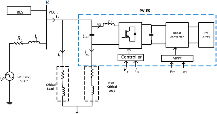
FIGURE 1. Schematic diagram of the PV-ES system.
2.1 Modeling of the PQ Controller
This section explores a novel active and reactive power control for ES by a local signal manipulation. A control loop is designed to achieve two objectives. One is to maintain constant real power to the critical load, regardless of the fluctuations in available power from renewable energy sources. Another is to regulate critical load voltage during voltage fluctuations. These objectives are accomplished by designing two control loops for real power control and voltage control to inject the ES voltage at the required phase angle.
The combined operation of the PI controllers is used to estimate the voltage
PCC voltage has two components. PCC voltage and currents with peak values
where ϕ and
If the d-axis of the rotating frame is aligned along the PCC voltage vector, then it can be rewritten as
where
Since the proposed ES is applied to a single-phase system, the reference voltage is the calculated
• Eliminates the need to identify the data of grid voltage.
• Decouples the control input active power and PCC voltage.
• Is simple to implement and has less computational burden compared to other techniques.
RMS value and the instantaneous phase of the critical load voltage are detected by the RMS and EPLL blocks, respectively. The powers
With reference to Eqs. 1, 2, the total apparent power consumed by the ES system is
For implementation in modeling, actual powers consumed are calculated as detailed in Figure 2:
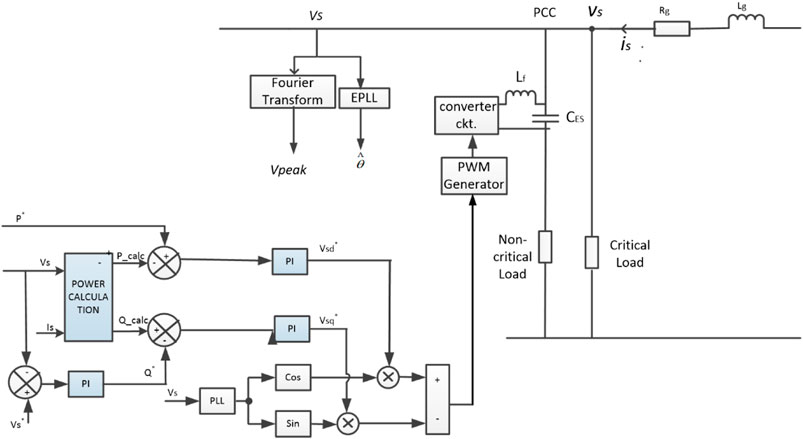
FIGURE 2. Block diagram representation of PQ control to ES.
If
Real power of critical load:
Reactive power of critical load:
2.2 Modeling of Photo-Voltaic System
The PV array is the combination of the PV modules. The primary element is the PV cell, which converts solar power to electrical power. Alrahim Shannan et al. (2013) detailed the different modeling of the PV cell as single diode model, two diode models, and multiple diode model. In this work single diode model of a PV cell is considered. Ipv is the photocurrent. D1 is an anti-parallel diode, Rp is leakage resistance, and Rs is contact resistance. V is the output voltage of the single cell, and the output current of cell I is given in Eq. 20:
Here, λ is the irradiation of solar, Iscr is cell shorted current, and Tk and Trefk are the actual and standard temperature. K is the temperature coefficient of short-circuit current (A/K), A1 is the ideality factors of the diodes. q is the charge of the electron, and Io1 are the reverse saturation currents of diodes. Eq. 21is modified for the PV module as given in Eq. 22.
Here, Ns and Np are the numbers of cells cascaded and shunted in the module. The PV module current is given in Eq. 24. These modules are connected in cascaded and shunted to meet the voltage and power rating. They form a PV array. The PV array current is given as follows:
where Nss and Npp are the numbers of series-connected and parallel-connected modules. The standard KC200GT data sheet parameters used to do the PV array simulation are given in Table 1.
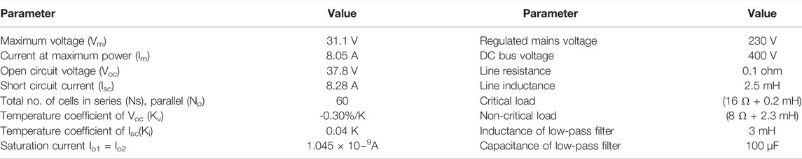
TABLE 1. System specifications.
Generally, a DC–DC boost converter is employed to increase the output voltage. It is shown in Figure 3. The inductor stores energy when the switch is ON, the stored energy is released to the load when it is OFF. MPPT controller generates reference voltage. The error voltage is given as input to the PI controller to generate a reference voltage signal for PWM control. It generates pulses to the boost converter and enables the boost converter to obtain the maximum power from the PV panel and maintain fixed DC link voltage. The ripple in DC link voltage is reduced by a capacitor filter given by Sano and Fujita (2008).
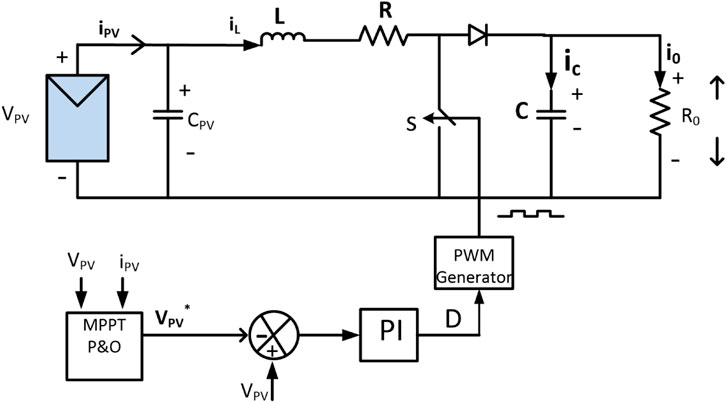
FIGURE 3. PV array with DC-DC boost converter and MPPT.
3 Performance of PV-ES System
The ES system with the parameters given in Table 1 is considered. The design of the parameters of the boost converter is given as follows (Veerachary and Sekhar, 2011):
Vs = source voltage, Vo = output voltage, D = duty cycle,
The PV array is designed for 480 V, 25 kW. The control circuit of the boost converter is designed for two purposes: maximum power extraction and maintaining DC link voltage constant. The solar panel is considered to operate at a temperature of 25° and insolation of 1,000 W/m2. In order to demonstrate the operation of PV-ES under the collective effect of changes in solar irradiation levels and PCC voltage, the irradiation level is maintained at 900 W/m2 from 0 to 2.5 s and then reduced to 600 W/m2 for the remaining period. The total simulation time is 4 s. PCC voltage change is studied for voltage sag of 184 V and swell of 276 V.
PV current and voltage before and after MPPT are given in Figures 4A,B, 5, respectively. These values are subjected to changes in solar irradiation at t = 3 s. These simulations indicate that PV voltage and current values are controlled to maintain an almost constant DC power of 700 W supplied to ES. Sag in PCC voltage occurs at t = 2 s. Instant radiation changes result in a discontinuity in the PV current from 2.5 to 2.75 s. A transient operation occurs for 0.25 s. For the first 2 s, the line voltage is maintained at the rated value of 230 V. At t = 3 s, its value is decreased to 184 V. However, due to the absorption of reactive power by ES, the PCC voltage is regulated to a rated value within 0.42 s as presented in Figure 6A.
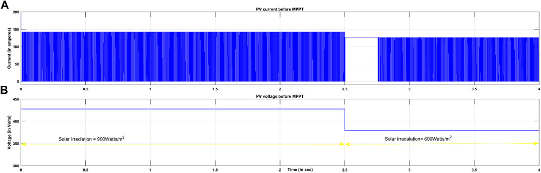
FIGURE 4. PV current and voltage before MPPT.
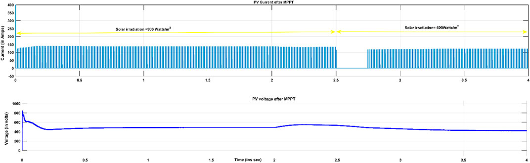
FIGURE 5. PV current and voltage after MPPT.

FIGURE 6. PV-ES for voltage sag.
Reference power of 6 kW is given, and it is observed from Figure 6B that the net real power absorbed by the smart load is maintained at the reference value of 6 kW very accurately with the transient operation of 0.25 s. It is observed from Figure 6C that the power flow from PV to ES is also maintained almost at a constant value of 700 W. Effective operation was achieved due to the control action of the DC value of PV-ES irrespective of change in solar irradiation. Voltage regulation for variation in PCC voltage is achieved due to the novel PQ control of the ES system.
Investigation of PV-ES for voltage swell and irradiation change is carried out in this section. Swell of 276 V in PCC voltage is simulated at 2 s. It is inferred that the PCC voltage is regulated to 230 V. Smart load is maintained at a reference of 6 kW. Though voltage swell occurs, active power consumption of the critical load is maintained constant at 3,300 W. These phenomena are detailed through the simulation results from Figures 7A–C. PV-ES regulates the build-up of the voltage potential across ES from 10 to 60 V. Subsequently, ES absorbs 75 VAr from the system. Controller action of PV-ES thus regulates PCC voltage to 230 V.
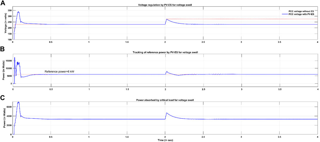
FIGURE 7. PV-ES for voltage swell.
3.1 Change in Reference Power at Fixed PCC Voltage and Varying Solar Irradiation
The performance of PV-ES is examined for changes in solar irradiation levels and reference power. Throughout the simulation time, the PCC voltage is maintained at a rated value of 230 V, whereas the reference power is decreased from 8 to 4 kW at t = 2 s. It is correlated with the change in solar irradiation from 900 to 600 W/m2. The output of the boost converter is also reduced from 600 to 380 V. Subsequently, power flow between ES and PV is affected by the value of reference power. When reference power is 8 kW, the power flow from PV to ES is 1.1 kW. When reference power is reduced to 4 kW, power flow from PV to ES is also reduced to 600 W. This is illustrated in Figure 8A.
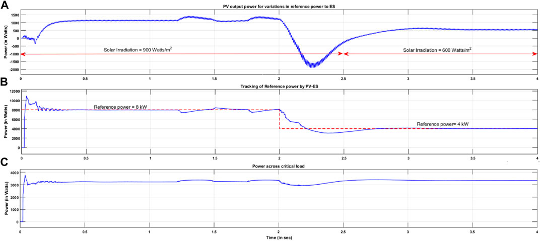
FIGURE 8. Performance of PV-ES under varying solar irradiations.
It is observed that, with the controller action, net real power absorbed by the smart load seamlessly tracks the reference power very accurately, as shown in Figure 8B. There is a steady-state error in tracking the reference power between the time intervals of 1.25–1.5 s due to the dynamics in the PV system. When the reference power changes, there is a transient time of 1 s. A peak overshoot of 1 kW from the steady-state value (4 kW) occurs at t = 2 s due to the large change in the reference power. The power absorbed by the critical load is maintained constant at 3.3 kW with a small transient operation at 2 s, as shown in Figure 8C. Steady-state errors during 1.25–1.5 s and from 1.75 to 2 s are cause by the transients in the PV power.
3.2 Comparison of ES Fed by DC Source and ES Fed by PV Source
This section investigates a comparison of the performance of the electric springs when fed by DC and PV sources. Tracking of reference power and voltage regulation is investigated under sag and swell conditions in the PCC voltage. The key points are transient time and peak overshoot.
Comparative analysis between the operations of ES when fed from the PV source and a DC source is numerically tabulated in Table 2. From Figure 9, it is observed that during voltage regulation, the time taken to track reference power is the same as that for both configurations. However, their performances for tracking reference power differ slightly under changes in voltage, as illustrated in Figure 10. In contrast, their performance is noticeably different to track variations in reference power as illustrated in Figure 11. Tracking reference power by PV- ES is better than DC-ES by 0.14 s.
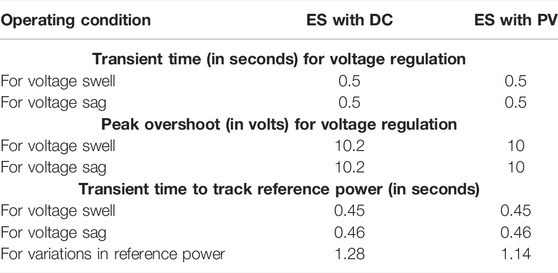
TABLE 2. Comparison of ES performance when fed with different sources.
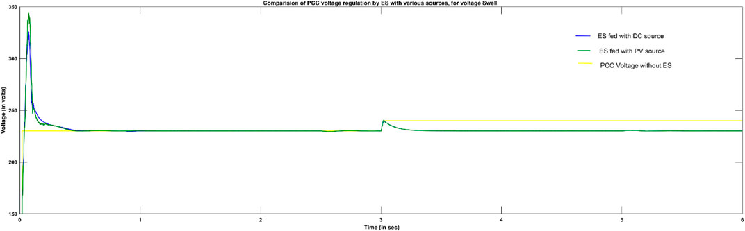
FIGURE 9. Comparison of voltage regulation for voltage swell.
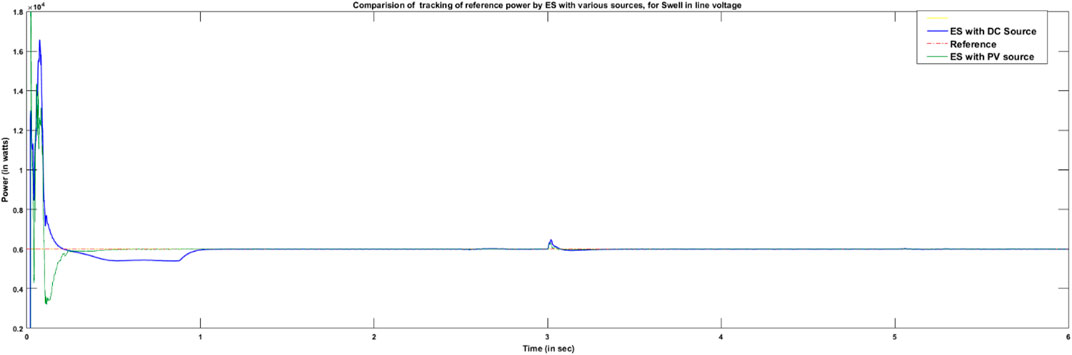
FIGURE 10. Comparison to track reference power for voltage swell.
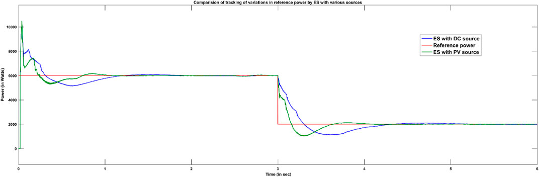
FIGURE 11. Comparison of tracking variations in reference power.
Table 2 also compares these two configurations in terms of peak overshoot and settling time during the voltage regulation. Transient time is controlled alike with both sources, whereas peak overshoot differs by 0.2 V during voltage sag.
4 Conclusion
The extensive analysis concludes that the overall performance of PV-ES is better when compared to DC-ES. Moreover, with the widespread roof-top PV sources in the distribution network, it is economical to employ PV as a source to the ES compared to a battery source (DC) to follow demand-side management (DSM). The voltage across the critical load is regulated to the pre-set value of 230 V by PV-ES, irrespective of variations in power available. With the PV-ES control, critical load power is maintained constant at 3.3 kW regardless of any change in the PCC voltage. For voltage variations of 20%, voltage regulation was restored at the same time of 0.5 s by both PV-ES and DC-ES. Peak overshoots are almost limited to 4% rated voltage with both configurations. Peak overshoot was 10.2 V with DC-ES that is 0.2 V more than PV-ES. Variations in reference power are quickly tracked by PV-ES in 0.14 s faster than DC-ES.
It is concluded that PV-ES demonstrates similar phenomena as ES fed with a DC source. Thus, it is more economical to operate smart loads by integrating with a renewable energy source of PV rather than a fixed DC source such as a battery. The capability of the proposed system is demonstrated to effectively mitigate changes in any practical operating factors such as PCC voltage, available power, and solar irradiation without violating voltage regulation and critical load requirements.
Data Availability Statement
The original contributions presented in the study are included in the article/Supplementary Material. Further inquiries can be directed to the corresponding author.
Author Contributions
RR proposed the concept of the project, and PR acted as the project administrator. KK, JV designed the system model and established the details of the power configuration scheme. PR carried out the simulation and SS prepared the Sections 1, 2 in manuscript. KK and RR analysed the data. All authors have read and agreed to the submitted version of the manuscript.
Conflict of Interest
The authors declare that the research was conducted in the absence of any commercial or financial relationships that could be construed as a potential conflict of interest.
Publisher’s Note
All claims expressed in this article are solely those of the authors and do not necessarily represent those of their affiliated organizations or those of the publisher, the editors, and the reviewers. Any product that may be evaluated in this article, or claim that may be made by its manufacturer, is not guaranteed or endorsed by the publisher.
References
Alrahim Shannan, N. M. A., Yahaya, N. Z., and Singh, B. (2013). “Single-diode Model and Two-Diode Model of PV Modules: A Comparison,” in 2013 IEEE International Conference on Control System, Computing and Engineering, Penang, Malaysia, 29 November 2013 - 01 December 2013, 210–214. doi:10.1109/ICCSCE.2013.6719960
Golestan, S., and Guerrero, J. M. (2015). Conventional Synchronous Reference Frame Phase-Locked Loop Is an Adaptive Complex Filter. IEEE Trans. Ind. Electron. 62 (3), 1679–1682. doi:10.1109/TIE.2014.2341594
Hui, S. Y., Lee, C. K., and Wu, F. F. (2012). Electric Springs-A New Smart Grid Technology. IEEE Trans. Smart Grid 3 (3), 1552–1561. doi:10.1109/TSG.2012.2200701
Khamis, A. K., Zakzouk, N. E., Abdelsalam, A. K., and Lotfy, A. A. (2019). Decoupled Control Strategy for Electric Springs: Dual Functionality Feature. IEEE Access 7, 57725–57740. doi:10.1109/ACCESS.2019.2914141
Lee, C. K., Li, S., and Hui, S. Y. (2011). A Design Methodology for Smart LED Lighting Systems Powered by Weakly Regulated Renewable Power Grids. IEEE Trans. Smart Grid 2 (3), 548–554. doi:10.1109/TSG.2011.2159631
Mok, K.-T., Tan, S.-C., and Hui, S. Y. R. (2016). Decoupled Power Angle and Voltage Control of Electric Springs. IEEE Trans. Power Electron. 31 (2), 1216–1229. doi:10.1109/TPEL.2015.2424153
Munoz, J. A., Espinoza, J. R., Baier, C. R., Moran, L. A., Espinosa, E. E., Melin, P. E., et al. (2012). Design of a Discrete-Time Linear Control Strategy for a Multicell UPQC. IEEE Trans. Ind. Electron. 59 (10), 3797–3807. doi:10.1109/TIE.2011.2160511
Nolan, S., and O’Malley, M. (2015). Challenges and Barriers to Demand Response Deployment and Evaluation. Appl. Energy 152, 1–10. doi:10.1016/j.apenergy.2015.04.083
Palensky, P., and Dietrich, D. (2011). Demand Side Management: Demand Response, Intelligent Energy Systems, and Smart Loads. IEEE Trans. Ind. Inf. 7 (3), 381–388. doi:10.1109/TII.2011.2158841
Sano, K., and Fujita, H. (2008). Voltage-Balancing Circuit Based on a Resonant Switched-Capacitor Converter for Multilevel Inverters. IEEE Trans. Ind. Appl. 44 (6), 1768–1776. doi:10.1109/TIA.2008.2006291
Shuo, Y., Tan, S.-C., Lee, C. K., and Hui, S. Y. R. (2014). “Electric Spring for Power Quality Improvement,” in 2014 IEEE Applied Power Electronics Conference and Exposition - APEC 2014, Fort Worth, TX, 16-20 March 2014, 2140–2147. doi:10.1109/APEC.2014.6803602
Tan, S.-C., Lee, C. K., and Hui, S. Y. (2013). General Steady-State Analysis and Control Principle of Electric Springs with Active and Reactive Power Compensations. IEEE Trans. Power Electron. 28 (8), 3958–3969. doi:10.1109/TPEL.2012.2227823
Veerachary, M., and Sekhar, R. (2011). “Voltage-mode Controller Design for Soft-Switching High Gain Boost Converter,” in India International Conference on Power Electronics 2010 (IICPE2010), New Delhi, India, 28-30 January 2011 (, 1–5. doi:10.1109/IICPE.2011.5728086
Wang, Q., Cheng, M., Jiang, Y., Zuo, W., and Buja, G. (2018). A Simple Active and Reactive Power Control for Applications of Single-phase Electric Springs. IEEE Trans. Ind. Electron. 65 (8), 6291–6300. doi:10.1109/TIE.2018.2793201
Westermann, D., and John, A. (2007). Demand Matching Wind Power Generation with Wide-Area Measurement and Demand-Side Management. IEEE Trans. Energy Convers. 22 (1), 145–149. doi:10.1109/TEC.2006.889551
Wu, T.-F., Kuo, C.-L., Sun, K.-H., and Hsieh, H.-C. (2014). Combined Unipolar and Bipolar PWM for Current Distortion Improvement during Power Compensation. IEEE Trans. Power Electron. 29 (4), 1702–1709. doi:10.1109/TPEL.2013.2265399
Keywords: electric spring, photovoltaic system, point of common coupling, critical load, MATLAB/Simulink
Citation: Kollipara KD, Vijay Kumar J, R P, Sura SR, Kumar Patnaik MSP and Ravi Sankar RS (2022) Energy Efficient Photovoltaic-Electric Spring for Real and Reactive Power Control in Demand-Side Management. Front. Energy Res. 10:762931. doi: 10.3389/fenrg.2022.762931
Received: 23 August 2021; Accepted: 07 June 2022;
Published: 13 July 2022.
Edited by:
Chandrasekhar Perumalla, Indian Institute of Technology Bhubaneswar, IndiaReviewed by:
Narottam Das, Central Queensland University, AustraliaRui Wang, Northeastern University, China
Copyright © 2022 Kollipara, Vijay Kumar, R, Sura, Kumar Patnaik and Ravi Sankar. This is an open-access article distributed under the terms of the Creative Commons Attribution License (CC BY). The use, distribution or reproduction in other forums is permitted, provided the original author(s) and the copyright owner(s) are credited and that the original publication in this journal is cited, in accordance with accepted academic practice. No use, distribution or reproduction is permitted which does not comply with these terms.
*Correspondence: Keerthi Deepika Kollipara, a2tkZWVwaWthMThAZ21haWwuY29t