- 1Digital Grid Research Institute of China Southern Power Grid, Guangzhou, China
- 2Guangdong Key Laboratory of Clean Energy Technology, School of Electric Power, South China University of Technology, Guangzhou, China
- 3Department of Electrical Engineering, School of Automation, Guangdong University of Technology, Guangzhou, China
- 4Brunel Interdisciplinary Power Systems Research Centre, Department of Electronic and Electrical Engineering, Brunel University London, London, United Kingdom
To fully reveal the interplay of the cyber system and physical system in the microgrid, this paper proposes a generic hierarchical modeling framework for cyber-physical integration modeling of microgrid, including two layers: physical device layer and controller layer. Each layer includes two parts: the continuous part (characterizing the physical system in the microgrid) and the discrete part (characterizing the cyber system in the microgrid). In this paper, firstly, detailed mathematical expressions describing the dynamic characteristics of each layer (including continuous characteristics and discrete characteristics) and describing the interplay of the continuous part and discrete part in each layer are given, which contributes to a better understanding of the interplay of the information flow and energy flow in the microgrid. Secondly, the cyber-physical integration modeling of each unit in the proposed framework is established using hybrid automaton, which can clearly present the operation state of each unit of the microgrid and its state transfer process, which is beneficial to design the optimal operation state trajectory of the system. The proposed modeling framework is generic and can be extended to any dynamic system with cyber-physical integration. Finally, a typical microgrid system is taken as an example to verify the feasibility of the proposed modeling approach.
1 Introduction
Cyber physical system (CPS) is a multidimensional heterogeneous complex system that integrates computing, network and physical environment (Zonouz et al., 2014; Gao et al., 2021). Compared with the traditional single physical system, CPS improves the operating efficiency of the system by integrating network, computing and physical resources (Poovendran, 2010). In recent years, the coupling of cyber space and energy system has become increasingly close with the rapid development of communication technology, sensor technology, computer technology and automatic control theory. The microgrid proposed to solve the problem of renewable energy grid-connection has increasingly possessed the key features of CPS (Cheng and Chow, 2020) and has developed into a typical microgrid CPS (MCPS). The cyber-physical coupling characteristic of MCPS has the function of energy management but it also brings the shortage that faults on any side will affect the safe and stable operation of the entire MCPS. Therefore, it is important to promote the development of MCPS that studies the coupling relationship from the perspective of CPS. The model is the basis for studying its coupling relationship (Ilic et al., 2010), so this paper mainly studies from the perspective of MCPS model.
There is a body of research that has focused extensively on the cyber-physical integration modeling of the power grid CPS. For example, Ref (Wei et al., 2014). established a power grid CPS (PGCPS) model that conforms to the characteristics of the actual PGCPS structure based on the analysis of the component configuration and coupling rules of the cyber network. Refs (Xin et al., 2015; Xin et al., 2017). proposes a two-layer multi-agent PGCPS framework that divides CPS clusters through cluster theory to achieve distributed control of PGCPS using less information. Refs (Yu et al., 2016; Li et al., 2020). built a PGCPS model based on the node-branch correlation matrix, which described the coupling of information and energy flows more comprehensively in the PGCPS, but it was difficult to quantitatively describe and analyze the stochastic events and complex response processes in the cyber system. Refs (Xue and Yu, 2017; Xu et al., 2019). used the matrix formed by multi-element tuple to quantitatively describe the association relationship of information processing layer, communication layer, secondary equipment layer, and physical space, which can effectively describe the coupling relationship within the PGCPS. Ref (Wang et al., 2017). established an integrated PGCPS model considering the correlation and coupling characteristics of the power network, communication network, and cyber network, which reveals the multilayer coupling association mechanism of PGCPS more clearly.
In summary, the above studies have proposed modeling methods for PGCPS from different perspectives, which can reveal the interaction between information flow and energy flow to a certain extent, but the objects of their studies are mainly PGCPS, and there are few studies involving the modeling of MCPS in the literature. Meanwhile, there are still some limitations that need to be solved in the above models:
a) The above modeling approaches are mainly performed from a task-specific perspective, not a generic modeling approach for the system, so their application fields are limited.
b) The existing modeling methods mostly focus on the static relationships in the system, lacking the modeling of dynamic process and evolution. Meanwhile, the above models cannot clearly present the operating status of each unit of the microgrid and its state transfer process.
The research in this paper attempts to address above issues. Therefore, in this paper, taking microgrid as the research object, a generic hierarchical modeling framework for integration modeling of MCPS, including two layers: physical device layer and controller layer, is proposed. To the best of the authors’ knowledge, the original contributions of this paper are summarized as follows:
1) Detailed mathematical expressions describing the dynamic characteristics of each layer (including continuous dynamic characteristics and discrete characteristics) and describing the interactions between the continuous part and discrete part within each layer are given, which contributes to a better understanding of the interplay of the information flow and energy flow in the MCPS;
2) In the established modeling framework, the cyber-physical integration modeling of each unit is established by using hybrid automaton (HA), which can clearly present the operating state, state transfer process, and transfer conditions of each unit in the microgrid. This is beneficial to design the optimal operation state trajectory of the microgrid and explore the optimal control strategy;
3) The proposed modeling framework divides the microgrid system modeling into different layers, which makes modeling more intuitive. Moreover, the proposed modeling framework is generic and can be extended to any dynamic system with cyber-physical integration.
2 Microgrid CPS architecture
2.1 The architecture of microgrid CPS
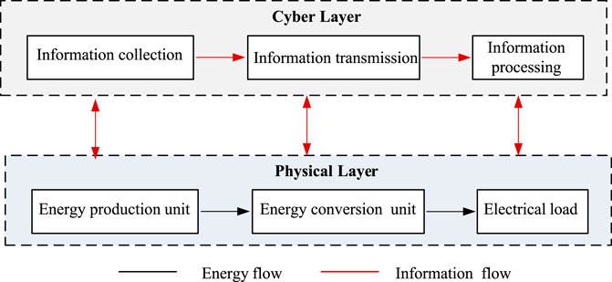
Figure 1 shows a typical MCPS architecture, which consists of two parts: the physical layer and the cyber layer. The physical layer is composed of energy production units (photovoltaic, wind power, energy storage, etc.), energy conversion units, various types of loads and other physical equipment, and the power network connecting these physical devices. The cyber layer is composed of cyber equipment such as sensing equipment, distributed computing equipment, control decision equipment and a communication network connecting these cyber devices.
In MCPS, the cyber layer and the physical layer have the function of the energy management of the microgrid through the tight coupling of information flow and energy flow. Cyber-physical coupling is manifested in that the cyber layer perceives the operating status of the equipment in the physical layer through sensors, converts the energy flow into an information flow, transmits it to the cyber layer through the communication network and the information flow is processed by the cyber processing unit as the input of the decision-making control unit. The decision-making control unit converts the input information into control instructions and sends them to the physical equipment in the physical layer to control the operation of the physical equipment. It can be seen that the information input of the cyber layer to make decisions comes from the operating status of the equipment in the physical layer. The operating status of the physical layer equipment depends on the control commands issued by the cyber layer, indicating that the cyber layer and the physical layer in the MCPS are tightly coupled.
2.2 The description of the hybrid system
The hybrid system (HS) can be formally described by the following multi-element tuple (Petreczky and Schuppen, 2297).
Where: M denotes the set of discrete states of the system (also called the mode of operation of the system), and for any one discrete state, there are
P denotes the parameter variable of the system;
R denotes the reset function, which determines the initial value of the continuous variable after the discrete state transition of the system occurs;
The dynamics of the HS can be described by the following equations.
Where the subscripts "+" denotes the state after the event e occurs and subscripts "−" denotes the state before the event e occurs,
Let t be the initial moment and the initial state of the system is
3 Hierarchical modeling framework for microgrid CPS
3.1 The hybrid characteristics of microgrid CPS
The MCPS presents a hybrid system characteristic during operation. For example, the energy flow in the physical system varies continuously with time according to a certain rule, which has the characteristics of a continuous variable dynamic system (CVDS). The cyber system controls the physical system through the information flow, including information collection, communication, processing, and control processes, all of which work digitally and consist of various types of events and their responses, which has the characteristics of a discrete event dynamic system (DEDS). Moreover, there is an interaction between the above two characteristics.
From the above analysis, it is clear that the physical system in the MCPS can be regarded as a CVDS, while the cyber system in the MCPS can be regarded as a DEDS. Therefore, the analysis of the interplay of information flow and energy flow in the MCPS can be converted into the analysis of the interplay of the CVDS and the DEDS in the MCPS.
3.2 The CPS-based modeling framework for microgrid
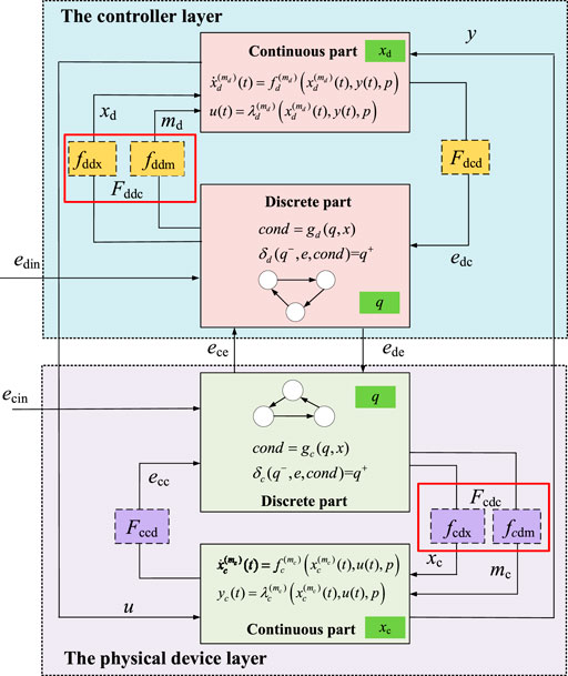
To accurately characterize the interplay of the information flow and energy flow in the MCPS, a generic hierarchical modeling framework for cyber-physical integration modeling of MCPS is proposed, as shown in Figure 2.
In Figure 2, the modeling framework of MCPS includes two layers: the physical device layer and the controller layer.
1) Physical device layer: This layer mainly includes some PV unit, WT unit, BSS unit, etc., which can be considered as a unit-level CPS. The unit-level CPS can optimize the allocation of resources within the working capacity of the device through the physical device, its control system, and communication modules. At this layer, each device in the physical device layer transmits information related to its state and sensed environmental information to the controller layer and executes control commands issued by the controller layer.
2) Controller layer: As the upper layer of the microgrid CPS, this layer, on the one hand, mainly issues control commands to the physical device layer to drive the actions of the units in the physical device layer. On the other hand, it mainly uses data fusion, distributed computing, big data analysis, and other technologies to monitor, analyze and control the whole working status of the system in real-time, to achieve the optimal configuration, decision, and operation of the system.
In Figure 2, both the physical device layer and the controller layer consist of two parts: the continuous part and the discrete part. The continuous part is used to describe the characteristics of the continuous change of the device state over time. While the discrete part is used to describe the transfer process of the device between different operating states. The continuous part and the discrete part interact with each other through interface functions.
4 Microgrid CPS modeling based on hybrid automaton
4.1 The mathematical description of each layer
4.1.1 The physical device layer.
i) The continuous part
In the continuous part, the continuous dynamic behavior of the device is characterized by the following equation.
Where,
ii) The discrete part
The discrete part is used to describe the transfer process of the device between different discrete states q, which can be described by the state transfer condition function gc and the state transfer function
The function gc
The (7) indicates whether the system satisfies the condition of operating state transfer by function gc under the condition of discrete state q and continuous state x.
The function
The event e can be a state event ecc generated by the continuous part, or an internal control input event ede of the system, or an event ecin generated by the environment. The (8) indicates that the system will transfer from state q− to state q+ and generate a series of discrete events ecdi when event e occurs and the transfer condition cond of the state is true.
iii) The interface layers
The interface layers include the discrete-continuous system interface and the continuous-discrete system interface. Define Fccd to denote the continuous-discrete interface layer function that represents the action of the continuous part on the discrete part. Similarly, define Fcdc to denote the discrete-continuous interface layer function that represents the action of the discrete part on the continuous part.
① The Fccd represents the action of the continuous part on the discrete part, which manifests in triggering an event ecc generated when the state trajectory of the x traverses the hypersurface hm, which acts on the discrete part through the event ecc, thus changing the value of q. For each mode
Then the expression that generates the event ecc is shown in Eq. 10.
② The Fcdc represents the action of the discrete part on the continuous part and consists of two parts, as follows.
In Eq. 11, the function fcdm manifests in affecting the dynamic evolution relationship of continuous variables x through the discrete state q, and its expression is as follows:
The (12) shows that the state mode m of the system is affected by q, while the device operates in different state modes m, there are corresponding differential equations to describe the dynamic behavior of the continuous part, i.e., the function fcdm influences the differential equations of the dynamic behavior of the continuous part through m.
When the system undergoes a state transfer, the value of the continuous state variable x may undergo a jump. The process is described by the function fcdx, and its expression is as follows
Where "+" indicates the state after the event and "−" indicates the state before the event. As can be seen from Eq. 13. The discrete part acts on the continuous part by generating the discrete event ecdi, which changes the value of the x.
In summary, the mathematical description of the dynamic characteristics of the continuous part, the discrete part, and the interface layers in the physical device layer are summarized as follows:
4.1.2 The controller layer
Similar to the physical device layer, the dynamic characteristics of each part in the controller layer can be described in Eq. 5:
4.2 CPS modeling of microgrid based on hybrid automaton
In this section, to clearly present the operation status, state transfer conditions, and state transfer process of each unit in the microgrid under the conditions of external control commands or various events, the cyber-physical integration modeling of MCPS is established using hybrid automaton (HA) (Lin et al., 2021). The HA is an extension of the original Finite State Machine (FSM) (Li et al., 2014), that is, continuous variables are added to the variables of the system and the influence of continuous variables is added to the state transfer process of the system.
The HA can describe the continuous dynamic behavior of the system as well as the discrete dynamic behavior of the system. An HA usually includes the following elements: 1) present state (the current state of the system), 2) conditions (also called events, when a condition is met, it will trigger the state transition of the system), 3) action (referring to the action executed after the system state transition condition is met) 4) second state (referring to the next state to be transitioned after the system state transition condition is met).
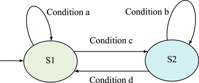
An HA is often represented by a directed graph and the state of the HA is represented by a circle. In each state, there is a function that describes how the continuous state changes. A directed curve is used to represent the state transition process of the system. The starting point of the directed curve represents the current state of the system and the end point represents the next state after the transition. At the same time, mark the transition conditions of the system state transition on the edge of the directed curve. Take an HA with two states as an example to illustrate the working principle of HA, as shown in Figure. 3.
The HA in Figure. 3 includes two states S1 and S2. The arrow pointing to S1 on the left indicates that the initial state of the system is S1. Above S1, draw a directed curve with the start and end points on S1. The condition a of state transition is marked on the curve, which means that when the system state is S1 and condition a is met, the state of HA remains unchanged; the directed curve marked with condition c from S1 to S2 shows that when the system state is S1 and condition c is satisfied, the system state is converted to S2. Similarly, according to the directed graph, when the system is in the S2 state, and the condition b is satisfied, the state of HA remains unchanged; when the condition b is satisfied, the system state changes to S1.
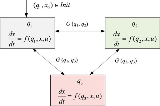
Taking the three states of a device in the MCPS as an example, the CPS model of the device is established using HA as shown in Figure. 4.
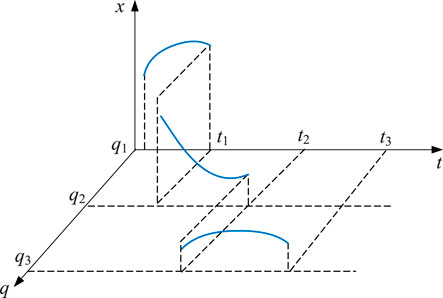
As seen from Figure 4, the transfer process between different states of the device can be described as follows: the trajectory of the device starts from the initial state, and the transfer process includes continuous state evolution and discrete state transfer. The initial discrete state of the device is q1, then the continuous variable x evolves according to the following differential equation.
As long as the state transfer condition function g () is not satisfied, the device keeps evolving in the current operating state, i.e., the discrete state q remains unchanged with q(t) = q1. And when the state transfer condition function G (q1, q2) is satisfied for some reason, the discrete state transfer of the system is triggered and the system changes from the discrete state q1 to the discrete state q2 according to the state transfer function
The evolution of the above device can be described by the evolutionary trajectory shown in Figure 5.
The transfer conditions between the different modes can be divided into two categories: internal state events due to the evolution of internal state variables across a specific threshold or state plane, and external state events due to the influence of external inputs (e.g., command issuance) on the system. These two types of events can act on the MCPS either individually or simultaneously.
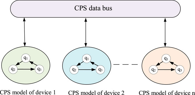
By connecting CPS models of the multiple devices established using HA in the MCPS through the CPS data bus, the CPS model of the entire microgrid system (i.e., the system-level CPS model) can be obtained, as shown in Figure 6.
As can be seen from Figure 6 that the operating process of the microgrid system can be characterized and analyzed by multiple state transfer models, and the transfer between different states is achieved using HA. In each operating state, the device’s continuous variation characteristics are described using differential or algebraic equations.
In summary, the microgrid model established in this paper is completely different from the conventional microgrid state space model in terms of the modeling approach and thinking and has more advantages in terms of observability. On the one hand, no matter what operating state the microgrid is in, the operating state of each unit in the microgrid can be known. On the other hand, during the transfer of the microgrid operating state, the operation state transfer process of each unit in the microgrid and the conditions of transfer can be clearly presented and observed, which is not available in the conventional state space model.
5 Model validation
5.1 Case description
This paper takes the operating mode of Interlinking Converter (ILC) in hybrid AC/DC microgrids (HMs) as an example to verify the modeling method proposed in this paper. Figure 7 corresponds to the topological structure diagram of the HMs in this example, which consists of an AC subgrid, a DC subgrid, and ILC connecting the AC subgrid and the DC subgrid.
Among them, an unbalanced load is connected to the AC bus. The unbalanced load will make the AC bus voltage uac and the ILC current iILC unbalanced. The DC bus voltage udc will produce ripple through the coupling effect of ILC. Since ILC does not run at rated power most of the time, we can make full use of the remaining available capacity of ILC to realize HMs power quality control, including balancing uac, iILC and suppressing ripple in udc. The specific principles are beyond the scope of this paper and are referred to the references (Nejabatkhah et al., 2018; Wang et al., 2018). Among them, ILC can be divided into different operating modes according to different control objectives.
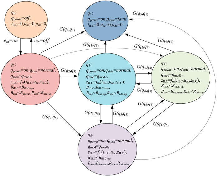
The different operating modes of ILC are realized by adjusting the equivalent impedance zILC of ILC. Different zILC corresponds to different operating modes. The switching between the different operating modes of ILC is determined by the imbalance degree of uac, iILC and the ripple ratio of udc. BiILC represents the unbalance degree of iILC. Buac represents the unbalance degree of uac. Rudc represents the ripple ratio of udc. BiILC-up represents the upper limit of BiILC. Buac-up represents the upper limit of Buac. Rudc-up represents the upper limit of Rudc. When BiILC is greater than BiILC-up, which means that the current imbalance of ILC exceeds the upper limit, ILC needs to switch to current imbalance compensation mode. Other situations are similar. The situation that two or three of iILC, uac, and udc exceed the upper limit is defined as an ILC fault state, and it is necessary to switch to the ILC fault state.
BiILC-stan represents the standard value of BiILC. Buac-stan represents the standard value of Buac. Rudc-stan represents the standard value of Rudc When ILC works in the current unbalance compensation mode, the ILC current balances. The condition that BiILC equals to BiILC-stan is satisfied. Other situations are similar and not mentioned here.
5.2 HA-based ILC model
According to the modeling method of part of the MCPS model in Section 4.2, the modeling process of ILC can be obtained as follows.
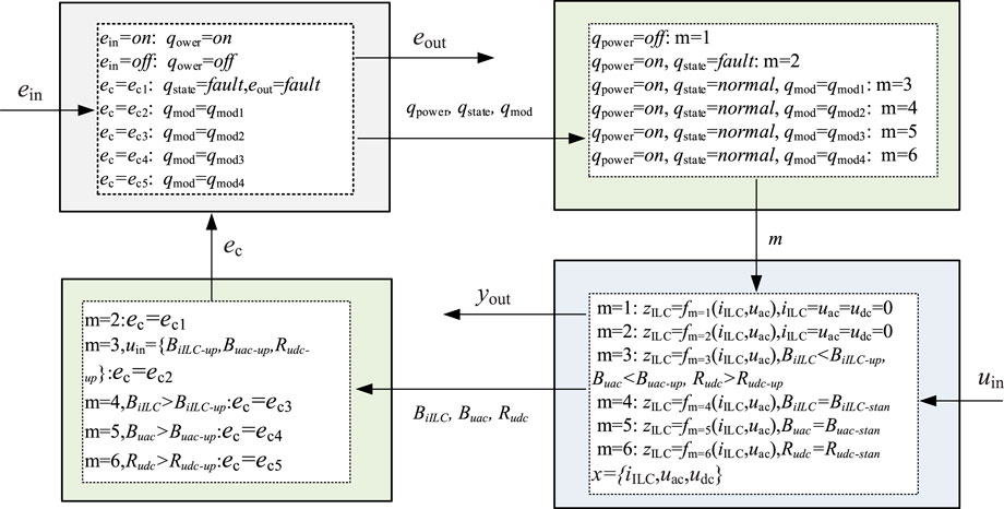
① Determine the input and output variables of ILC:
Input variables include external input control command ein and continuous input variable uin. Among them,
The output variables include yout and the output event signal eout which indicates ILC failure, among them
② Determine the state variables of the ILC:
Discrete variable
Continuous variables
③ Determine the transition function of continuous system and discrete system and the function of interaction between the two: define the value of parameter m as 5, and continuous system has different update functions under different values. The realization of the multi-mode operation of ILC is essentially achieved by adjusting the equivalent impedance zILC of ILC, so the update function of the continuous system is the function of adjusting the ILC equivalent impedance zILC, that is fm (zILC, iILC, uac). The discrete system acts on the continuous part by the value of m.
Define five hypersurfaces hi, which are used to generate five continuous events ec, and influence the discrete system through ec. Among them,
The model of ILC can be obtained as shown in Figure 8 according to the definition of the above elements. The above model can describe the effect of external input on ILC, and the relationship between internal state and input-output. The transition process and conditions of ILC between different states can be described by the model in Figure 9.
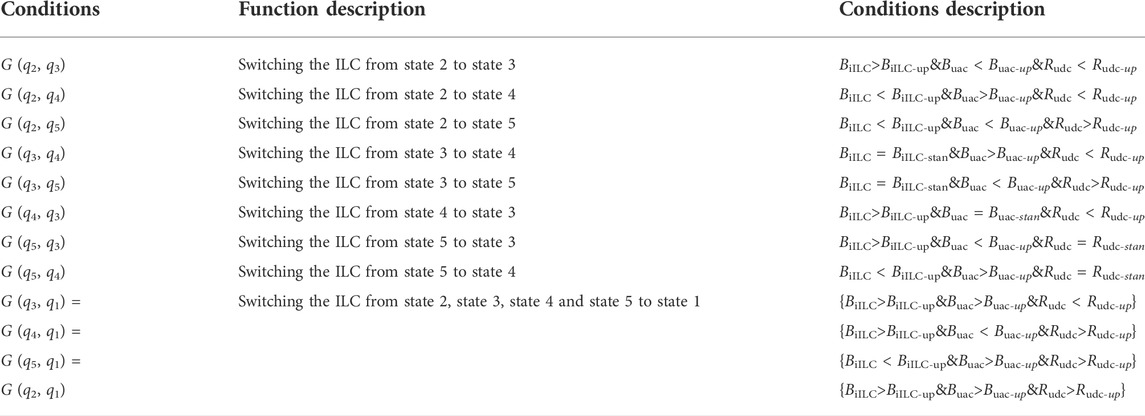
The conversion conditions between the different modes in Figure 9 are shown in Table 1
5.3 Simulation analysis
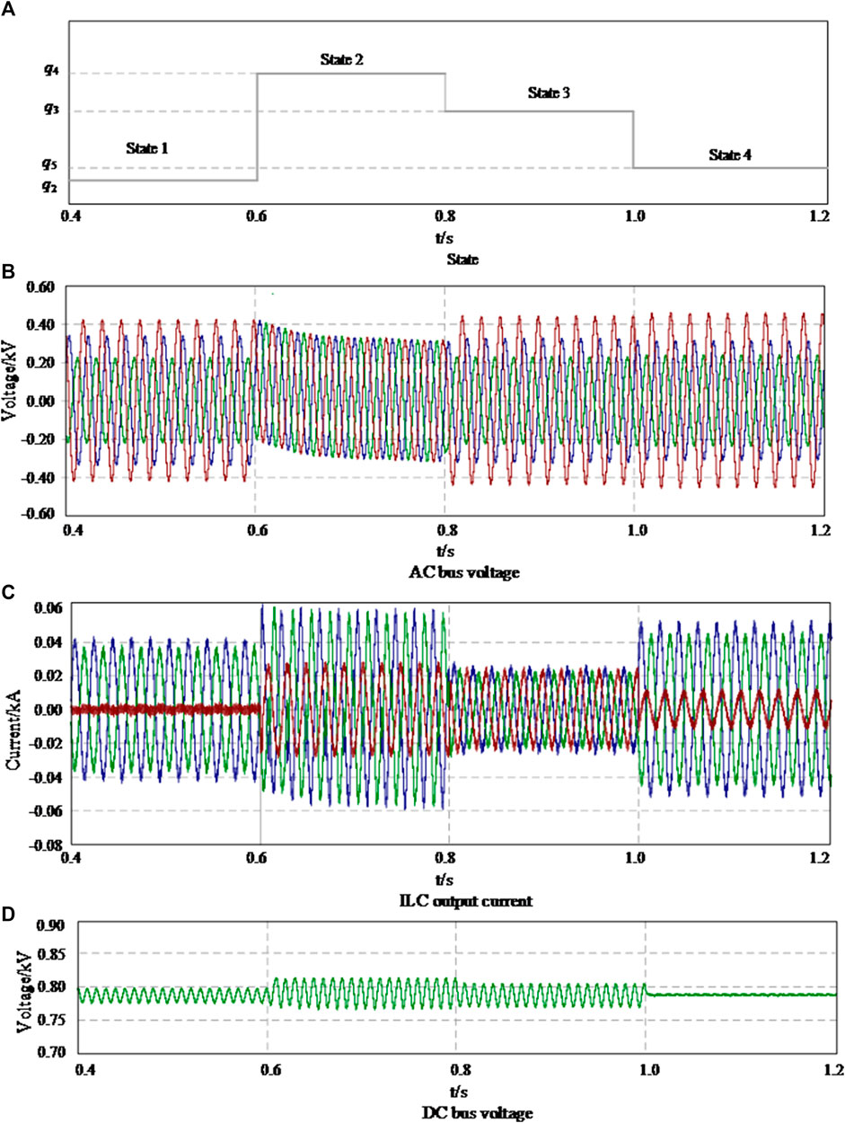
Take the transition from state 3 to state 4 as an example to illustrate the transition process of ILC between different modes. When ILC is in state 3, ILC works in the current imbalance compensation mode. The output current of ILC is basically balanced, as shown in Figure 8C, but the AC bus voltage uac is unbalanced, as shown in Figure 8B. The DC bus voltage udc produces ripple, as shown in Figure 8D. When Buac is greater than Buac-up for some reason, adjust the impedance zILC of the ILC to make ILC run from state three to state four. At this time, ILC works in AC bus voltage negative sequence compensation mode, AC bus voltage uac is basically balanced, but ILC output current iILC becomes unbalanced, and DC bus voltage udc produces ripple. The transition process between the other modes is similar. The waveform of the conversion process of ILC in different working states in Figure 7 above is obtained as shown in Figure 10, based on the simulation model shown in Figure 9 built by the PSCAD simulation software. Among them, state 1, state 2, state 3 and State 4 respectively correspond to the uncontrolled mode, ILC output current imbalance compensation mode, AC bus voltage imbalance compensation mode and DC bus voltage ripple suppression mode.
Take the transition from state 3 to state 4 as an example to illustrate the transition process of ILC between different modes. When ILC is in state 3, ILC works in the current imbalance compensation mode. The output current of ILC is basically balanced, as shown in Figure 10C, but the AC bus voltage uac is unbalanced, as shown in Figure 10B. The DC bus voltage udc produces ripple, as shown in Figure 10D. When Buac is greater than Buac-up for some reason, adjust the impedance zILC of the ILC to make ILC run from state three to state four. At this time, ILC works in AC bus voltage negative sequence compensation mode, AC bus voltage uac is basically balanced, but ILC output current iILC becomes unbalanced, and DC bus voltage udc produces ripple. The transition process between the other modes is similar.
6 Conclusion
To fully reveal the interplay of the cyber system and physical system in the microgrid and present the operation state of each unit in the microgrid and its state transfer process, this paper takes the continuous operation characteristics and discrete process of the microgrid into consideration and establishes the cyber-physical integration modeling of MCPS. The main conclusions are as follows:
1) A generic hierarchical modeling framework applicable to the modeling of the MCPS is proposed, which is divided into the physical device layer and controller layer. And detailed mathematical expressions describing the dynamic characteristics of each layer and the interactions between layers are given, which contributes to a better understanding of the interplay of the information flow and energy flow in the MCPS;
2) The cyber-physical integration modeling of the MCPS is established using HA, which can clearly present the operation state of each unit in the microgrid and its state transfer process. This is beneficial to design the optimal operation state trajectory of the system and explore the optimal control strategy; The model established from the perspective of generality can be extended to any dynamic system of cyber-physical integration, and the model established is more intuitive and easy to extend.
The CPS model of the MCPS established in this paper will be applied in detail in the future work, including the use of the established model to guide the planning of the microgrid system, the design of the optimal system strategy, etc.
Data availability statement
The original contributions presented in the study are included in the article/Supplementary Material, further inquiries can be directed to the corresponding author.
Author contributions
PL: methodology, conceptualization and funding acquisition. FZ: software and writing—original draft preparation. XM: formal analysis. SY: investigation and resources. PY: writing—review and editing. YY: reference searching and visualization. ZZ: validation. CL: supervision. LL: data curation. All authors have read and agreed to the published version of the manuscript.
Funding
This research was funded by The Research Project of Digital Grid Research Institute, China Southern Power Grid under Grant YTYZW20010, and in part by the National High Technology Research and Development Program of China (863 Program) under Grant 2014AA052001.
Conflict of interest
The authors declare that the research was conducted in the absence of any commercial or financial relationships that could be construed as a potential conflict of interest.
Publisher’s note
All claims expressed in this article are solely those of the authors and do not necessarily represent those of their affiliated organizations, or those of the publisher, the editors and the reviewers. Any product that may be evaluated in this article, or claim that may be made by its manufacturer, is not guaranteed or endorsed by the publisher.
References
Cheng, Z., and Chow, M. Y. (2020). Resilient collaborative distributed energy management system framework for cyber-physical DC microgrids. IEEE Trans. Smart Grid 11 (6), 4637–4649. doi:10.1109/TSG.2020.3001059
Gao, C., Wang, T., Cao, H., Wang, Z., Yu, T., Cheng, R., et al. (2021). Concepts, structure and developments of high-reliability cyber-physical fusion based coordinated planning for distribution system. Front. Energy Res. 9, 697959. doi:10.3389/fenrg.2021.697959
Ilic, M. D., Xie, L., Khan, U. A., and Moura, J. M. F. (2010). Modeling of future cyber–physical energy systems for distributed sensing and control. IEEE Trans. Syst. Man. Cybern. A 40 (4), 825–838. doi:10.1109/TSMCA.2010.2048026
Li, H., Dimitrovski, A., Song, J. B., Han, Z., and Qian, L. (2014). Communication infrastructure design in cyber physical systems with applications in smart grids: A hybrid system framework. IEEE Commun. Surv. Tutorials 16 (3), 1689–1708. doi:10.1109/surv.2014.052914.00130
Li, M., Xue, Y., Ni, M., and Li, X. (2020). Modeling and hybrid calculation architecture for cyber physical power systems. IEEE Access 8 (99), 138251–138263. doi:10.1109/ACCESS.2020.3011213
Lin, T., Chen, Z., Zheng, C., Huang, D., and Zhou, S. (2021). Fault diagnosis of lithium-ion battery pack based on hybrid system and dual extended Kalman filter algorithm. IEEE Trans. Transp. Electrific. 7 (1), 26–36. doi:10.1109/tte.2020.3006064
Nejabatkhah, F., Li, Y., and Sun, K. (2018). Parallel three-phase interfacing converters operation under unbalanced voltage in hybrid AC/DC microgrid. IEEE Trans. Smart Grid 9 (2), 1310–1322. doi:10.1109/TSG.2016.2585522
Petreczky, Mihály, and Schuppen, J. H. V. (22972010). Realization theory for linear hybrid systems. IEEE Trans. Autom. Contr. 55 (10), 2282–2297. doi:10.1109/tac.2010.2044258
Poovendran, R. (2010). Cyber–physical systems: Close encounters between two parallel worlds [point of view]. Proc. IEEE 98 (8), 1363–1366. doi:10.1109/JPROC.2010.2050377
Wang, T., Nian, H., Zhu, Z. Q., Ding, L., and Zhou, B. (2018). Flexible compensation strategy for voltage source converter under unbalanced and harmonic condition based on a hybrid virtual impedance method. IEEE Trans. Power Electron. 33 (9), 7656–7673. doi:10.1109/TPEL.2017.2768381
Wang, Y., Liu, D., and Sun, C. (2017). A cyber physical model based on a hybrid system for flexible load control in an active distribution network. Energies 10 (3), 267. doi:10.3390/en10030267
Wei, J., Kundur, D., Zourntos, T., and Butler-Purry, K. L. (2014). A flocking-based paradigm for hierarchical cyber-physical smart grid modeling and control. IEEE Trans. Smart Grid 5 (6), 2687–2700. doi:10.1109/TSG.2014.2341211
Xin, S., Guo, Q., Sun, H., Zhang, B., Wang, J., and Chen, C. (2015). Cyber-physical modeling and cyber-contingency assessment of hierarchical control systems. IEEE Trans. Smart Grid 6 (5), 2375–2385. doi:10.1109/tsg.2014.2387381
Xin, S., Guo, Q., Sun, H., Zhang, B., Wang, J., and Chen, C. (2017). Cyber-physical modeling and cyber-contingency assessment of hierarchical control systems. IEEE Trans. Smart Grid 6 (5), 2375–2385. doi:10.1109/TSG.2014.2387381
Xu, L., Guo, Q., Yang, T., and Sun, H. (2019). Robust routing optimization for smart grids considering cyber-physical interdependence. IEEE Trans. Smart Grid 10 (5), 5620–5629. doi:10.1109/TSG.2018.2888629
Xue, Y., and Yu, X. (2017). Beyond smart grid—Cyber–physical–social system in energy future [point of view]. Proc. IEEE 105 (12), 2290–2292. doi:10.1109/JPROC.2017.2768698
Yu, W., Xue, Y., Luo, J., Ni, M., Tong, H., and Huang, T. (2016). An UHV grid security and stability defense system: Considering the risk of power system communication. IEEE Trans. Smart Grid 7 (1), 491–500. doi:10.1109/TSG.2015.2392100
Keywords: microgrid, hybrid automaton, cyber-physical system, modeling framework, physical device layer
Citation: Li P, Zhang F, Yang Y, Ma X, Yao S, Yang P, Zhao Z, Lai CS and Lai LL (2022) The integrated modeling of microgrid cyber physical system based on hybrid automaton. Front. Energy Res. 10:748828. doi: 10.3389/fenrg.2022.748828
Received: 28 July 2021; Accepted: 08 July 2022;
Published: 05 August 2022.
Edited by:
Muhammad Wakil Shahzad, Northumbria University, United KingdomReviewed by:
Muhammad Ahmad Jamil, Northumbria University, United KingdomFubin Yang, Beijing University of Technology, China
Copyright © 2022 Li, Zhang, Yang, Ma, Yao, Yang, Zhao, Lai and Lai. This is an open-access article distributed under the terms of the Creative Commons Attribution License (CC BY). The use, distribution or reproduction in other forums is permitted, provided the original author(s) and the copyright owner(s) are credited and that the original publication in this journal is cited, in accordance with accepted academic practice. No use, distribution or reproduction is permitted which does not comply with these terms.
*Correspondence: Yi Yang, ZXB5YW5neWkxOTkyQG1haWwuc2N1dC5lZHUuY24=
 Peng Li1
 Yi Yang
 Zhuoli Zhao
 Chun Sing Lai
 Loi Lei Lai