 Zhi Xu
 Shakenbieke Alimasibieke1,2
- 1Xinjiang Electric Power Research Institute of State Grid Xinjiang Electric Power, Co., Ltd., Urumqi, China
- 2Xinjiang Key Laboratory of Whole Process Simulation for Power System, Urumqi, China
The power system is migrating to 100% penetration of the converter-interfaced generation (CIG). The grid-forming converter-based CIG has been proposed to be a solution to replace the synchronous generation (SG) in order to form the grid and achieve the 100% penetration target. However, besides the generation, whether the protection system can coordinate this transition is still an open question. Although the grid-forming converter operates as the same manner as the SG, unlike SG, it physically has constraints on its current output which in transient leads to different operation to the SG. This paper aims to investigate whether these different transients have effects on the protection system, specifically, investigate if the protection system remains reliable when the system migrates to 100% penetration. The investigation is based on the hardware in-the-loop experiment, considering different converter control, different type of the fault, different length of the line and different fault location. The result shows that the grid-forming converter has a reliable coordination with the protection system in response to the fault.
1 Introduction
Due to the global drive towards a 100% penetration of renewable in the power system, converter-interfaced generation (CIG), such as photovoltaic (PV) systems and wind turbines, are being widely integrated into the present power system (Xie et al., 2014). Most of the existing CIG are grid-feeding/following (Rocabert, 2012), using a phase locked loop to follow the grid frequency and purely feeding the power to the grid, so that essentially they behave like a current source. However, in the transition to the replacement of the synchronous generation (SG) by CIG, some of the CIG must assume the responsibility of the SG to form the grid and consequently behave as voltage sources (Chen and O'Donnell, 2019a; Chen et al., 2020a). According to Hennig, 2019 and ENTSO-E (2017), in a fully non-synchronous system at least 30% of the generation should be the grid-forming for the sake of the power system stability. ENTSO-E (2017) presents some considerations for the implementation of grid-forming converters in national grid-codes.
The grid-forming converter typically applies outer voltage inner current controls thus controlling the output voltage directly in terms of both amplitude and phase. Its output power is the consequence of the difference between the grid voltage and controlled output voltage. Conversely, the control of the power and voltage amplitude can lock the phase (Xiong et al., 2021), thus maintaining a power based synchronization with the grid (Tayab et al., 2017) analogous to the SG. The implementation of the power synchronization control can be as simple as a proportional gain from the power to the converter frequency, defined as droop control and widely used in microgrids (Tayab et al., 2017), or PID control for the fast stabilization (Zhang et al., 2010), or the use of the swing equation (D'Arco and Suul, 2014), defined as virtual synchronous generator control (VSG) (D'Arco et al., 2015; Zhong, 2016). VSG control has the advantage of using control parameters which have a direct analogy with SG characteristics such as inertia, damping, automatic voltage regulation (AVR), and turbine governor (TG). Chen et al. (2019) showed that a VSG with correspondingly identical settings to the SG can have exactly the same response as the SG in terms of system support and power generation.
However, if VSG controlled grid-forming converters are to replace the SG then they should also be coordinated with the protection system. Although the design and analysis of the VSG topology (D'Arco et al., 2015; Zhong, 2016), its functionality (Alipoor et al., 2015; Liu et al., 2015) and stability (Chen and O'Donnell, 2019b) have been well investigated, very little previous work has addressed the grid-forming converter interaction with the existing protection systems during a fault event. Unlike the SG, which can tolerate overcurrent for a certain time, the converter has a rigid constraint on the current to avoid overcurrent damage. The grid-feeding converter, due to its direct current/power control, can limit its current by use of the simple inclusion of a saturation or limiting block on its current Xiong et al. (2015) and Liu et al., 2022. In contrast, directly imposing a current limit in the grid-forming converter can lead to synchronization instability. This is because the grid-forming converter under power synchronization, controls the voltage directly and if the converter moves to constant current control under fault conditions it can lead to the accumulation of error in the power control and hence result in the synchronization instability (Chen et al., 2020b). To address this problem, voltage limitation methods (Shi et al., 2018; Chen et al., 2020b) for the grid-forming converter have been proposed in order to limit the current while maintaining the stability. Grid codes generally require that the CIG should remain connected, i.e., have fault ride through capability for various voltage reductions and durations (Luo et al., 2018). Some codes, e.g., Germany, requires maximum reactive power compensation from the CIG during the fault to aid voltage stability. This action also provides fault current during the fault and affects the action of the relay. It has been shown that the current limitation of the grid-feeding converter, in some cases (depending on the fault type, location, and converter loading), suppresses the fault current and adversely leads to the maloperation of the relay (Chavez, 2018). In addition, the lack of negative sequence current due to the converter control during asymmetrical faults has been observed as a problem for the protection system (Martínez et al., 2020). Several works have analyzed the fault impedance and designed novel protection algorithms for the case of high penetrations of grid-feeding converters (Pradhan and Joós, 2007; Hooshyar et al., 2014; Dubey et al., 2020; Liu et al., 2022). However, there have been no reports of work investigating the effects of the grid-forming converters on protection systems. Since the grid-forming converter presents low series output impedance, in contrast to the grid-feeding converter which presents high parallel output impedance (Rocabert, 2012), this difference has consequences for the fault impedance thus resulting in a different response from the protection system. In many respects (inertia, damping, voltage forming) the grid-forming converter operates in the system in a manner similar to the SG. However, the question remains as to how similar its performance is in terms of interaction with the protection system and hence what changes if any need to be implemented in existing protection systems. This paper addresses this question using hardware in the loop testing of conventional protection relays under different levels of CIG penetration. It aims to quantify the performance of existing distance relay protection systems in response to different CIG penetration (from 0% to 100%), different fault locations (0% distance of the line to 100%) and different fault types (line to line, line to ground and symmetric fault). The work is based on experiments performed using a real time simulation with hardware in the loop platform (RTDS platform).
The paper is structured as follows: Section 2 briefly reviews the control of the grid-feeding and grid-forming converters regarding fault-ride-through, and analyses their interaction with the relay. Section 3 introduces the hardware in-the-loop setup for the test of the protection system in response to the CIG. Section 4 compares the grid-forming CIG with SG in the absence of current limitations, from the hardware test result, while Section 5 compares the grid-forming CIG with grid-feeding CIG considering the current limitation. Section 6 draws conclusions for the paper.
2 Converter interfaced generator
CIG can be controlled as either grid-feeding or grid-forming. Correspondingly, the control of the grid-feeding and grid-forming CIG is different, and they present different output impedance to the system. This fact influences the protection systems in place today. Therefore, before testing the performance of the protection system, this section reviews the control scheme of the grid-feeding and grid-forming CIG and analyzes their coordination with protection system during faults.
2.1 Grid feeding converter
Grid-feeding converters apply outer power, inner current control behaving like current sources, and presenting high parallel output impedance as illustrated in Figure 1. The power control loop is an algebraic equation used to compute the current reference, while the current control loop is critical to the dynamics and typically applies a PI or PR controller to regulate the output current to track its reference. Thus, this type of converter directly controls the power/current flow from the CIG injected to the grid, and its output voltage at the PCC point is only indirectly controlled in order to impose the required power/current. The synchronization of the grid-feeding converter is achieved by the PLL. When the phase is successfully locked, the active and reactive powers of the converter are fully decoupled and can be precisely controlled. Using this advantage, separate active and reactive power regulation can be used to support the frequency and voltage respectively, e.g. frequency to active power droop (1) and voltage to reactive power droop (2).
where
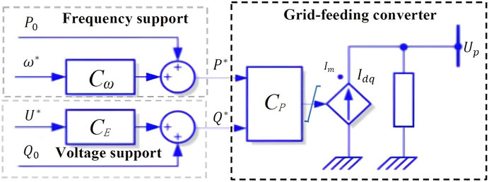
FIGURE 1. Grid-feeding converter.
The converter has a strict current limitation. Since the grid-feeding converter controls the current directly, the current limit can be implemented as a saturation block on the current reference as presented in Figure 1.
The value of the current limit depends on the grid code requirements. For example, the German Grid Code requires the maximum reactive power during the fault, so that when the PCC voltage is less than .5 pu, then the value of the current limit can be set as (3).
where
2.2 Grid-forming converter
Grid-forming converters apply outer voltage, inner current control behaving like voltage sources, and presenting a low series output impedance as illustrated in Figure 2. Both the voltage and current control loops typically apply PI or PR controllers to regulate the output voltage to track its reference. Thus, this type of converter directly controls the output voltage and its power/current is the consequence of the difference between the controlled voltage and the grid voltage. The reference to the grid-forming converter is the voltage. The voltage phase is related to the synchronization of the converter and is locked by power synchronization control. Although as mentioned earlier, different power to phase angle controllers are possible, VSG control emulates the dynamics of an SG so that its control parameters have a direct analogy with the inertia and damping of the SG, thus it has become a popular method for implementing grid-forming controls. The control algorithms for the VSG approach are given in (4).
where (4) is a representation of the electro-mechanical dynamics of the SG, i.e., the swing equation, where
where
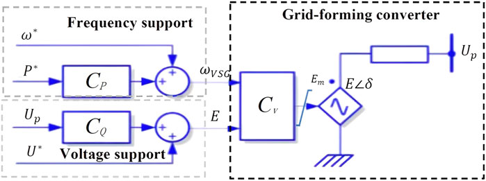
FIGURE 2. Grid-forming converter.
Since the grid-forming converter controls the voltage but not the current directly, it needs a special method for current limitation. One method is to increase the damping (Wei et al., 2017) of the grid-forming converter during the fault in order to slow down the movement of the phase to avoid the phase instability when the power in (4) is unbalanced. This works in the case of a fast fault clearance and low loading with initially small phase. However, if the fault cannot be cleared in time or the initial phase is large enough, the phase can exceed 90° and the converter becomes unstable. An alternative approach is to use the voltage limit to constrain the phase and amplitude of the output voltage (Shi et al., 2018; Chen et al., 2019), corresponding to active and reactive power regulation respectively, during the fault in order to suppress the current within the limit. The grid-forming converter voltage and power at its terminal is:
Substituting (3) into (6) and (7), then the active power reference in (4) should set to be zero and the voltage amplitude should be set to as (6) in order to maximize the reactive power compensation.
where
2.3 Comparison in respect to relay operation
Assuming the outer L-filter impedance is purely inductive, then the output power from the converter to the PCC can be represented as (9) and (10).
If the current limitation of the grid-forming converter is neglected, then during the fault corresponding to either a
The inclusion of the voltage limit (8) in the grid-forming converter limits the current to
The controlled current limited state, i.e., (8) for the grid-forming converter and (3) for grid-feeding converter, presents a similar final fixed operating point during the fault, however, the way in which they approach this operating point is totally different for the two converter types. For example, for the operation of the grid-forming converter as described in previous paragraph, at the instant of the fault, the converter output voltage does not change resulting in an increased fault current. The current measurement detects this fault current, and after the measurement delay, this overcurrent activates the voltage limitation control which changes the voltage reference (8). After a time, which depends on the speed of the voltage controller (typically >10 ms), the current is suppressed. Although at this time the current is limited, the stability of the grid-forming converter depends on the time constants of the power synchronization control, which could be on the order of seconds if using VSG control. For the grid feeding converter, which is under direct current control, at instant of the fault, the output current may increase for a time until the current controller reacts to maintain the current reference. In the time frame of the current control reaction (<1 ms), the grid-feeding converter can be stabilized. In summary, during faults, the grid-forming converter initially supplies a fault current and subsequently moves to work in current limitation, while the grid-feeding converter shows very little fault current due to its fast response on current limitation. The fault current in the grid-forming converter can help trip the protection system. It should be noted that this fault current in the grid-forming converter lasts only for the first one or two cycles, which is acceptable for the converters (Katiraei et al., 2012; SMA Solar Technology, 2012).
On the other hand, during an asymmetric fault or unbalanced PCC voltage situation,
From the preceding discussion it might be expected that the grid-forming converter should have a better performance than the grid-feeding converter in terms of coordination with the protection system in response to both symmetric and asymmetric faults.
3 Hardware in the loop testing
In order to test the relay performance in the presence of different types of the CIG at different penetration levels, a simulation of a test system with an EMT model of the CIG devices is built in RSCAD and interfaced to actual relays through a hardware in loop setup using an RTDS platform. Figure 3 (top) depicts the test system, where a slack generator is connected to the common bus of the wind generator and synchronous generator via a transmission line. The protection device is installed on the CIG side of the transmission line, shown as Z in Figure 3, and utilizes a distance protection function which is one of the most commonly used protection functions in transmission networks (Mason et al., 2009; ENTSO-E, 2018; ENTSO-E, 2019). Two transmission lines lengths of 10 km and 200 km are used for the testing. The analog signals representing the test system currents and voltages at the end of the protected line are sent out from the RTDS via an analog output card (GTAO) and then amplified from ± 10 V to ± 100 V/1 A by the power amplifier which feeds the actual relays. Binary signals, trip (per phase) from the relays are sent back to the RTDS via a digital card (GTDI). The total generation of the grid is 200 MW shared by the SG and CIG. It is assumed that the CIG works on a constant wind with constant power output. The CIG parameters used in the test system are given in Table 1.
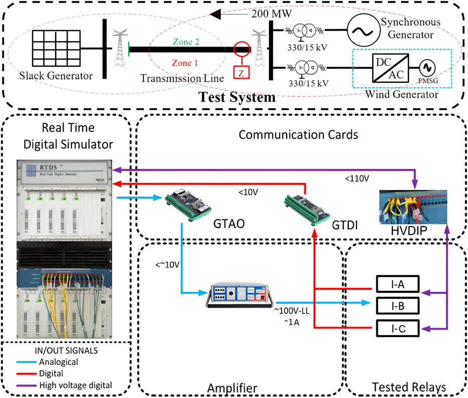
FIGURE 3. Hardware in-the-loop set-up.
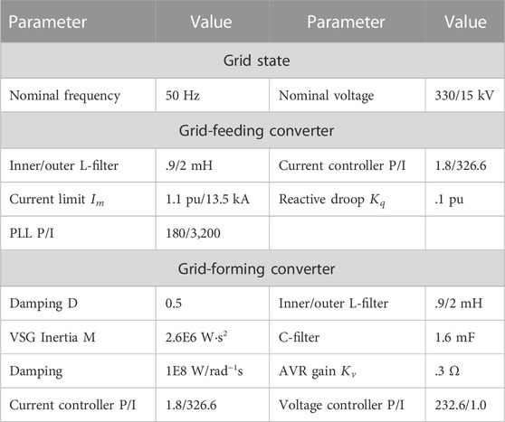
TABLE 1. Testing system settings.
The behaviors of the tested CIGs in the open-loop, including unlimited grid-forming converter, limited grid-forming converter and limited grid-feeding converter, are shown in Figure 4, where the relay and SG is disconnected, and the tested CIG connects to the mashed grid directly. The CIG experiences the reference power change from 0 to 100 MW at 05 s, and then a symmetric three-phase to ground fault at 3 s.
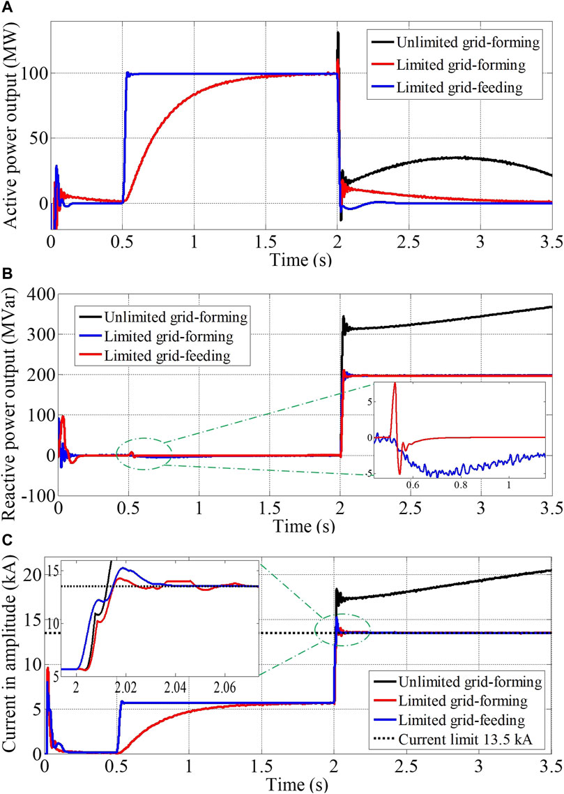
FIGURE 4. Open-loop Comparative Results. (A) Active power; (B) Reactive power; (C) Current in amplitude.
It can be seen from Figure 4A that after the reference power changes to 100 MW, the grid-feeding converter step changes to the same value, while the grid-forming converter presents the damping effect due to the VSG control strategy. On the other hand, due to the decoupled power control in grid-feeding converter, the reactive power remains at 0 MVar, but the grid-forming converter has a certain reactive power output around −3 MVar as shown in the zoom-in graph of Figure 4B. At the instant of the fault, 3 s, if without the limit, the grid-forming converter output power step down, resulting the converter acceleration and phase increase. The controlled voltage E increases as commended by (5), leading to a booming reactive power and current as indicated in (8). Although the converter may be damaged due to the overcurrent, the boosted reactive power supports the voltage stability and the overcurrent excites the relay reaction.
The inclusion of the limitation effectively limits the current in 3 cycle, .06 s for both grid-forming and grid-feeding converter as shown in Figure 4C. According to the German grid code, the reactive power is maximized, and the active power is minimized. Although the grid-forming converter applies (6) and grid-feeding converter applies (3) in the purpose of the current limitation, since the converter parameter,
The conducted tests are a closed-loop, where the relay measures the signals coming from real-time simulation and the tripping of the relay is looped back to the simulator. The simulator records the time between fault inception and protection trip (tripping time) under different conditions. The variables used for the simulations are listed as follows.
1) Two different transmission lines: For the purpose of a high and a low short-circuit ration conditions (SCR), a10 km line for high SCR and a 200 km line for a low SCR, for which the positive-, and zero-sequence impedance are given in Table 2.
2) Three different types of CIG: grid-feeding converter with current limit, grid-forming converter without limit and grid-forming converter with voltage limit. The grid-forming converter uses VSG control with a large damping for the fault ride through.
3) Five different CIG penetration levels: 0%, 25%, 50%, 75%, 100%. In 0% CIG penetration, the CIG is disconnected, while in 100% CIG penetration, the SG is disconnected.
4) Five different fault locations: 0%, 25%, 50%, 75%, 100% of the line length between the fault and the protection
5) Three type of faults: line to line fault (LL), single line to ground (LG), three-phase to ground (LLLG).

TABLE 2. Tested transmission line impedance.
Tests are repeated 5 times per condition to check the consistency of the results. If there is a ridiculous result attributing to the experimental bugs, the corresponding condition would be re-tested. A total of 2,250 simulations were performed. In order to clearly illustrate the effect of the control (type) of the CIG in different penetration levels, the paper only presents a representative selection of the results in order to illustrate the following aspects.
1) A comparison of the grid-forming converter without current limit to the SG. Since in the absence of a current limit, the grid-forming converter operates in the same manner as the SG. It would be expected that the relay would show the same performance in the system for both grid-forming converters and SG.
2) A comparison of the grid-forming converter with voltage limit to the grid-feeding converter with current limit. In practical applications, the converter current should be limited to avoid the overcurrent damage. Although the grid-forming applies the voltage limit, it fundamentally aims to limit the current. In this case, the relay may have a similar performance to grid-feeding if their saturated current is identical.
The comparison of the two aspects above is done based on the test results from the relay while changing the transmission line length as indicated in Table 3, the CIG penetration as shown in Figures 5–7, and the fault location as shown in Table 4 and fault type. The tripping time of the missed trip is set to be 1,000 ms. The qualified tripping time should be less than 250 ms for a fault located at a distance of 100% of the line (considered to be in zone 2) and less than 60 ms in other locations (considered to be in zone 1). Tripping times in excess of this are taken as a delayed relay operation.
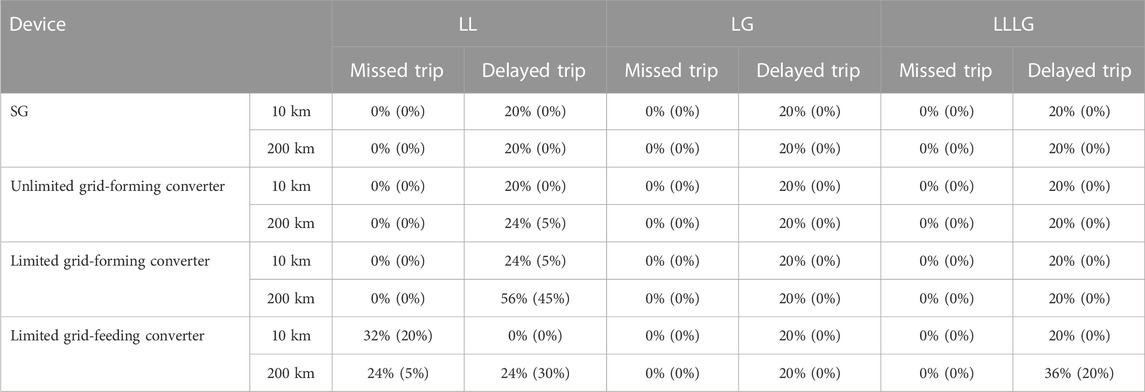
TABLE 3. Percentage of missed and delayed trips per type of fault per device, zone 1 result in brackets, zone1+zone2 result besides.
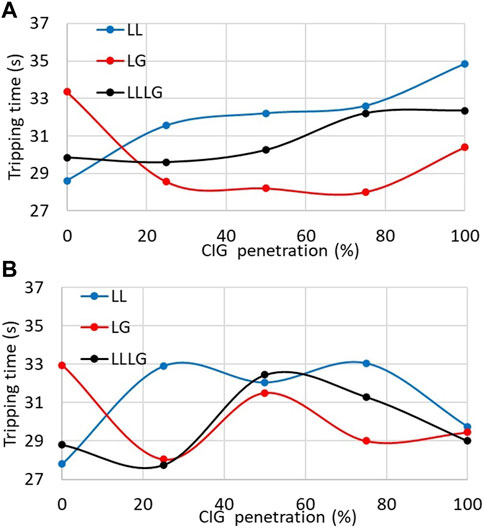
FIGURE 5. Protection tripping times using Unlimited grid-forming converter with respect to CIG penetration increase. (A) Tripping time on 10 km transmission line; (B) Tripping time on 200 km transmission line.
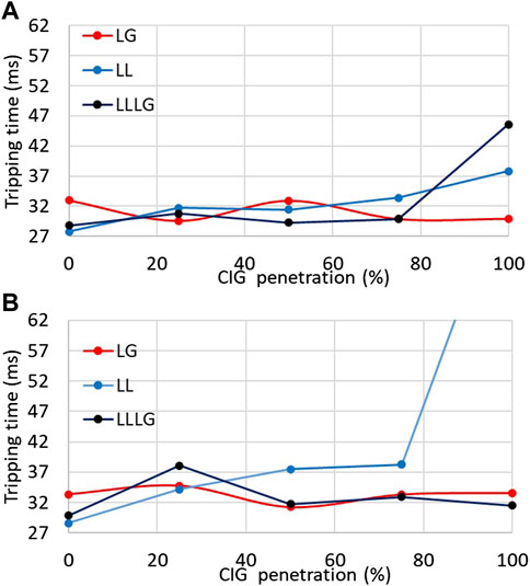
FIGURE 6. Protection tripping times using limited grid-forming converter with respect to CIG penetration increase. (A) Tripping time on 10 km transmission line; (B) Tripping time on 200 km transmission line.
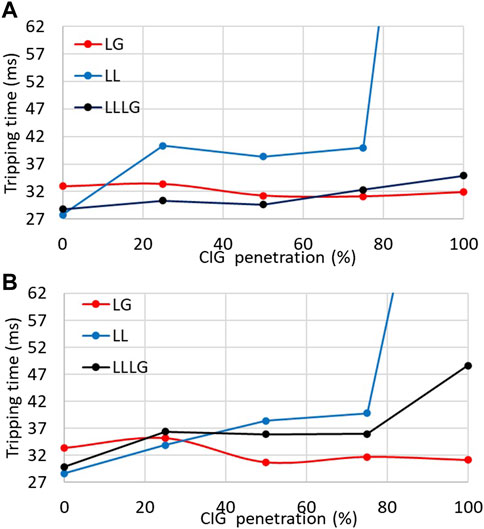
FIGURE 7. Protection tripping times using limited grid-feeding converter with respect to CIG penetration increase. (A) Tripping time on 10 km transmission line; (B) Tripping time on 200 km transmission line.
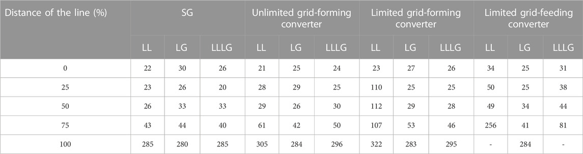
TABLE 4. Average tripping time for different fault distances for different faults and devices (Unit: ms).
4 Grid forming converter VS. SG
As analyzed in Section 2.3, the grid-forming converter without a current limit would be expected to have the same response to the fault as the SG. The main difference between both is their output impedance. This section compares the grid-forming converter with the SG in terms of the interaction with the protection system.
Table 3 shows the relay performance under the full supply from a single device, i.e. 100% penetration of the type of generating device in question. Performance is reported in terms of the percentage of missed or delayed trips in response to different types of fault at all line locations (in zone 1 and zone 2). The percentages shown in brackets give the percentages of missed or delayed trips for faults in zone 1 only, i.e., excluding those faults at 100% line length which fall in zone 2. It can be seen that there are no missed trips of the distance protection relays when the system is fed solely from the SG and or solely from the unlimited grid-forming converter in either the case of the 10 km and 200 km transmission lines. For the faults at the end of the transmission line, in both cases the relay has a delayed trip. This is as expected from the relay operation as faults at the end of the line (100% of the line in Table 4) appear in the second zone of protection and have an inherent delay of 250 ms to provide selectivity with respect to other protection, i.e., in practice, there would be another relay at the other end of line which should trip first. If we look at the relay trip time (not considering the 250 ms delay due to faults at 100% of the line length) the relay response with the SG and grid-forming converter are nearly identical. There is only one delayed trip with the grid-forming converter during the LL fault for the 200 km line.
Figure 5 shows the measured tripping times for the gradual replacement of the SG by the unlimited grid-forming converter, where 0% represents the system fed solely from an SG and 100% represents the system solely fed from CIG. The average tripping time is computed under the assumption that the fault at all locations are treated equally and does not include faults located at 100% of the line distance. It can be seen that as penetration levels of unlimited grid-forming converter generation increases the tripping time barely changes, varying between 27 and 36 ms under different conditions. The type of the fault and length of the transmission line have no influence on the tripping time with regards to the CIG penetration. This verifies that the unlimited grid-forming converter as expected has the same interaction with the distance protection relay as the SG.
5 Grid forming converter vs. grid-feeding converter
In practice, the converter must use a current limit to avoid the overcurrent damage. As a result the grid forming converter acts like a current source, when in current limited operation during a fault. With the same current limits, both the grid-forming and grid-feeding converters will limit the current at the same value, however their transient operation in transition to current limit mode is different as analyzed in Section 2.3. It might be expected that the voltage source would have better coordination with the relay than the current source. This section presents the effect of the current limitation on the relay tripping times and compares the situation for the grid-forming converter and the grid-feeding converter.
5.1 Effect of the limitation on the grid-forming converter
It can be seen from Table 3 that the inclusion of the limitation on the grid-forming converter, as expected, has a negative impact on the relay in response to the LL fault, due to a hard current suppression. The probability of the missed trip for a LL fault increases from 0% to 5% in a 10 km transmission line and from 5% to 45% in a 200 km transmission line, after the inclusion of the limitation. The average tripping time for a LL fault in each location exceeds 60 ms, around 110 ms, for a fault locating over 25% of the 200 km transmission line as shown in Table 4. The relay interacts with the limited grid-forming converter on the 200 km line and has worse performance than that on the 10 km line. This is because the line impedance is increased for the longer line which leads to a larger voltage drop on the line, resulting in a lower PCC voltage in (8) and a harder suppression on the current.
The inclusion of the limitation on the grid-forming converter has no influence on the relay trip times in response to an LLLG fault, which displays a tripping time in the range of 25–46 ms as shown in Table 4. This is because the fault current in the first two cycles can reliably activate the relay, which will be verified in Section 5.3.
In response to an LG fault, the relay works properly whether the converter includes the limit or not. This is because in this case the converter current does not saturate so that the grid-forming converter works in the same manner as the SG. During the LG fault, the power in one phase reduces but it remains the same in the other two phases. However, because of the immediate output power reduction and consequent loss of power balance in the controlling swing equation, the converter virtual speed slowly increases. This results in a slow increase in output current which helps to trip the relay before the converter current saturates. It should also be noted that a major influencer in LG faults is the grounded neutral points of the transformers. Both of the transformer neutrals, that connect the generating units to the grid, are grounded and hence in the case of the LG fault provide a path for zero-sequence current.
5.2 Comparison with limited grid-feeding converter
Although the limited grid-forming converter delays the relay trip for an LL fault, the limited grid-feeding converter gives rise to the probability of a missed trip as shown in Table 3. This is due the lack of negative-sequence current in the grid-feeding converter due to the use of direct balanced current control.
On the other hand, for a LLLG fault, the tripping time of the limited grid-feeding converter is increasing with distance to the fault location, while the tripping times for the limited grid-forming converter are relatively independent of fault location as shown in Table 4. This is due to the soft current suppression in the grid-feeding converter while the grid-forming converter has an inevitable transient fault current, which is shown later in Figure 8. Consequently, the grid-feeding converter causes delayed tripping with 20% probability in a 200 km transmission line.
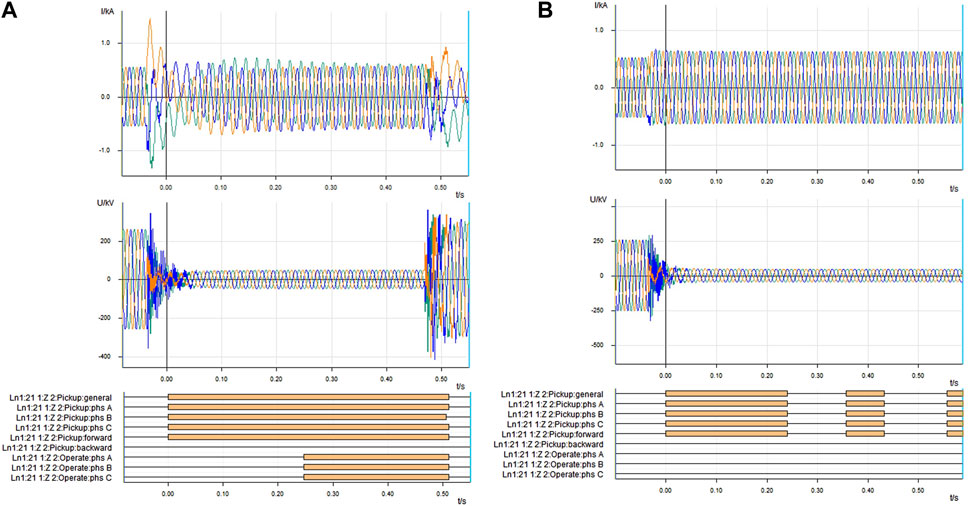
FIGURE 8. Relay measurements and signals during LLG fault at 100% of 200 km line. (A) shows relay measurements and signals with a limited VSG and (B) shows relay measurements and signal with a limited grid-feeding converter.
Figures 6, 7 presents the relay average tripping times versus the CIG penetration increase for the limited grid-forming and grid-feeding converter cases respectively. It can be seen that the increase of the CIG penetration has no and only limited influence on the LG and LLLG fault tripping time respectively but increases the tripping time for the LL fault for both converters. Especially, under 100% CIG penetration, the grid-feeding converter shows a significant tripping time increase, due to its balanced current control resulting in the lack of negative-sequence current in the system after the disconnection of the SG. While the grid-forming converter does not have this problem for its balance voltage control with acceptance of any sequence current.
Taking into account the standard maximum protection pickup time of 60 ms, the limited grid-forming converter can be used in a shorter transmission line with no changes on protection system achieving very high even 100% CIG penetration, while the grid-feeding converter is not comparable.
5.3 Measurements and signals of the relay
In order to see the relay action with respect to the grid-forming and grid-feeding converter, Figure 8 shows a comparison of the measurements and signals of the protection devices in both cases. The case shown is for a 200 km long transmission line with a fault at the end of the line. The signals and measurements with limited grid-forming converters are presented in Figure 8A and for a grid-feeding converter in Figure 8B. First part of the diagram shows relay current and voltage measurements, from which it can be observed that for the limited grid-forming control algorithm there exists a transient in the fault current but for the grid feeding converter there is no transient, which corresponds with the explanation provided in Section 2.3. In addition, it is seen that the fault current contribution from both of the converter types is almost the same at about 1.1 pu, which accords with the current limit set for both types of converters.
Distance protection operation and pickup signals are displayed on the lower part of Figure 8. When observing the response to the limited grid-forming converter (Figure 8A), it is seen that after the initial transient the fault is picked up correctly by the protection in all three phases and in the forward direction. The fault remains picked up by the protection for the entire duration of the fault and after the zone timer of 250 ms a trip signal is generated from zone 2. The total tripping time for this particular case including the relay pick up time is 280 ms.
When looking at the protection response in the case of a grid feeding converter in Figure 8 (B it can be observed that, similarly to the limited grid-forming converter, the initial pickup of the relay is delayed by about 30 ms. In this case, however, as seen from relay digital signals, the protection stops detecting the fault in the forward direction and due to this the relay pickup drops out at 240 ms after the first pickup by the relay. This means that the zone timer of 250 ms will not expire and the protection does not operate. It should be noted that during the fault the relay intermittently keeps picking up and dropping out although the current and voltage waveforms during the fault are uniform.
Figure 9 displays the impedance measurements by the relay during the fault condition. The blue line on the figure shows the impedance locus measurement and the red polygon shows the distance protection zone 2 characteristic.
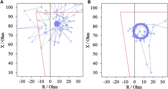
FIGURE 9. Relay impedance measurements during the fault. Blue line shows the impedance locus measurement and red polygon represents the distance protection zone 2 characteristic. (A) shows relay measurement with a limited grid-forming converter and (B) shows relay measurement with a grid feeding converter.
From both Figures 9A, B it is seen that during the fault the impedance measured falls into the distance protection zone and remains in the zone. The blue line shows the impedance locus measurement and the red polygon represents the distance protection zone 2 characteristic. In Figure 9A the impedance measurement for the case of limited grid-forming converter is shown. From there, it is observed that the impedance at the first 2 cycles of the fault is quite scattered and some measurements points are not in the zone. This is because of the transient at the beginning of the fault and is the reason why the protection operation is a little delayed. After the initial period the fault impedance settles inside the protection characteristic.
For the grid-feeding converter the impedance measured, shown on Figure 9B, falls into the distance protection characteristic immediately after the fault occurrence and forms a circular pattern inside the protection zone. Despite this the protection does not operate because of the directional element of the relay drops out after 240 ms after fault inception.
6 Conclusion
The paper presented the operation of protection relays in response to different fault under different levels of CIG penetration for both grid-feeding and grid forming CIG. Results are obtained from the hardware in-the-loop experiments using commercial distance protection relays. The following conclusions can be drawn.
1) Unlimited grid forming and SG give almost identical responses for protection relays for all types of fault. This is because of their voltage source characteristics, which naturally raises the short-circuit current.
2) When current limits are imposed, LL faults prove to be the most difficult for the protection system. There is an increased probability of delayed trips for limited grid forming and significantly increased tripping times, especially on the longer lines, but it does not cause any miss-tripping.
3) The limited grid feeding gives less reliable protection performance under LL faults with a significant increase in probability of missed trips due to its negative-sequence control loop and under LLLG faults with an increase in probability of delayed trips.
In conclusion from the perspective of protection system the usage of grid-forming converter is a better solution in the case of a high CIG penetration in the power system. The future work will compare different fault ride through strategies of the grid-forming converter with respect to the interaction with the protection system.
Data availability statement
The original contributions presented in the study are included in the article/Supplementary Material, further inquiries can be directed to the corresponding author.
Author contributions
Conceptualization, ZX; methodology, ZX and SA; software, ZX; validation, BZ and QY; resources, YW; data curation, YW; writing—original draft preparation, ZX; Table drawing, SA; writing—review and editing, BA and QY; project administration, ZX; funding acquisition, ZX. All authors have read and agreed to the published version of the manuscript.
Funding
This research was funded by the Technology Programme of State Grid Xinjiang and, grant number 5230DK22000V.
Conflict of interest
Author ZX was employed by the company Xinjiang Electric Power Research Institute of State Grid Xinjiang Electric Power, Co., Ltd.,
The remaining authors declare that the research was conducted in the absence of any commercial or financial relationships that could be construed as a potential conflict of interest.
The authors declare this study received funding from State Grid Xinjiang Electric Power, Co., Ltd. The funder had the following involvement in the study: data collection and decision to publish.
Publisher’s note
All claims expressed in this article are solely those of the authors and do not necessarily represent those of their affiliated organizations, or those of the publisher, the editors and the reviewers. Any product that may be evaluated in this article, or claim that may be made by its manufacturer, is not guaranteed or endorsed by the publisher.
References
Alipoor, J., Miura, Y., and Ise, T. (2015). Power system stabilization using virtual synchronous generator with alternating moment of inertia. IEEE J. Emerg. Sel. Top. Power Electron. 3 (2), 451–458. doi:10.1109/JESTPE.2014.2362530
Chavez, J. (2018). “Exposing available distance relay operations near high wind penetration,” in 9th Protection, Automation and Control (PAC) World Conference (Sofia, Bulgaria.
Chen, J., Liu, M., Milano, F., and O’Donnell, T. (2020a). 100% converter-interfaced generation using virtual synchronous generator control: A case study based on the Irish system. Electr. Power Syst. Res. 187, 106475. doi:10.1016/j.epsr.2020.106475
Chen, J., Liu, M., and O'Donnell, T. (2019). “Replacement of synchronous generator by virtual synchronous generator in the conventional power system,” in 2019 IEEE Power and Energy Society General Meeting (PESGM) (IEEE). doi:10.1109/PESGM40551.2019.8973650
Chen, J., and O'Donnell, T. (2019a). Analysis of virtual synchronous generator control and its response based on transfer functions. IET Power Electron. 12 (11), 2965–2977. doi:10.1049/iet-pel.2018.5711
Chen, J., and O'Donnell, T. (2019b). Parameter constraints for virtual synchronous generator considering stability. IEEE Trans. Power Syst. 34 (3), 2479–2481. doi:10.1109/TPWRS.2019.2896853
Chen, J., Prystupczuk, F., and Donnell, T. O. (2020b). Use of voltage limits for current limitation in grid-forming converters. Chin. Soc. Electr. Eng. J. Power Energy Syst. 6 (2), 11. doi:10.17775/CSEEJPES.2019.02660
D'Arco, S., and Suul, J., A. (2014). Equivalence of virtual synchronous machines and frequency-droops for converter-based microgrids. Smart Grid Trans.5, 394–395. doi:10.1109/TSG.2013.2288000
D'Arco, S., Suul, J. A., and Fosso, O. B. (2015). A virtual synchronous machine implementation for distributed control of power converters in smart grids. Electr. Power Syst. Res. 122, 180–197. doi:10.1016/j.epsr.2015.01.001
Dubey, R. K., Popov, M., and Chavez, J. (2020). “Low latency stockwell transform based secured distance protection scheme for power network connected with high renewable penetration,” in Ninth Protection, Automation and Control (PAC) World Conference. doi:10.5281/zenodo.3635350
ENTSO-E (2017). High penetration of power electronic interfaced power sources (HPoPEIPS). Avenue de Cortenbergh 100, Brussels, Belgium: European Network of Transmission System Operators for Electricity.
ENTSO-E (2018). Best protection practices for HV and EHV AC-transmission systems of ENTSO-E electrical grids. Avenue de Cortenbergh 100, Brussels, Belgium: European Network of Transmission System Operators for Electricity.
ENTSO-E (2019). Short circuit contribution of new generating units connected with power electronics and protection behavior. Avenue de Cortenbergh 100, Brussels, Belgium: European Network of Transmission System Operators for Electricity.
Hennig, J. (2019). Deliverable D1.5 Power system risk analysis and mitigation measures. MIGRATE 9 (15).
Hooshyar, A., Azzouz, M. A., and El-Saadany, E. F. (2014). Distance protection of lines connected to induction generator-based wind farms during balanced faults. IEEE Trans. Sustain. Energy 5 (4), 1193–1203. doi:10.1109/TSTE.2014.2336773
Katiraei, F., Holbach, J., Chang, T., Johnson, W., Wills, D., Young, B., et al. (2012). “Investigation of solar PV inverters current contributions during faults on distribution and transmission systems interruption capacity,” in Western Protective Relay Conference, 70–78.
Liu, J., Miura, Y., and Ise, T. (2015). Comparison of dynamic characteristics between virtual synchronous generator and droop control in inverter-based distributed generators. IEEE Trans. Power Electron. 31 (5), 3600–3611. doi:10.1109/TPEL.2015.2465852
Liu, X., Wu, B., and Xiu, L. (2022). A fast positive-sequence component extraction method with multiple disturbances in unbalanced conditions. IEEE Trans. Power Electron. 37 (8), 8820–8824. doi:10.1109/TPEL.2022.3161734
Liu, X., Xiong, L., Wu, B., Qian, Y., and Liu, Y. (2022). Phase locked-loop with decaying DC transient removal for three-phase grids. Int. J. Electr. Power and Energy Syst. 143, 108508. doi:10.1016/j.ijepes.2022.108508
Luo, X., Wang, J., Wojcik, J. D., Wang, J., Li, D., Mihai, D., et al. (2018). Review of voltage and frequency grid code specifications for electrical Energy storage applications. Energies 11 (5), 1070. doi:10.3390/en11051070
Martínez, E., Villén, M. T., Borroy, S., Grasset, H., and Dubey, R. K. (2020). ffects of Type-4 Wind Turbine on Present Protection Relaying Algorithms. Ninth Protection, Automation and Control (PAC) World Conference. doi:10.5281/zenodo.3635325
Pradhan, A. K., and Joós, G. (2007). Adaptive distance relay setting for lines connecting wind farms. IEEE Trans. Energy Convers. 22, 206–213. doi:10.1109/TEC.2006.889621
Rocabert, J., Luna, A., Blaabjerg, F., and Rodriguez, P. (2012). Control of power converters in ac microgrids. IEEE Trans. Power Electron. 27 (11), 4734–4749. doi:10.1109/TPEL.2012.2199334
Shi, K., Ye, H., Xu, P., Zhao, D., and Jiao, L. (2018). Low voltage ride through control strategy of virtual synchronous generator based on the analysis of excitation state. IET Generation Transm. Distribution 12 (9), 2165–2172. doi:10.1049/iet-gtd.2017.1988
SMA Solar Technology, AG. (2012). Technical information short-circuit currents: Information on short-circuit currents of SMA PV inverters. 1–5.
Tayab, U. B., Bin Roslan, M. A., Hwai, L. J., and Kashif, M. (2017). A review of droop control techniques for microgrid. Renew. Sustain. Energy Rev. 76 (SEP.), 717–727. doi:10.1016/j.rser.2017.03.028
Wei, F., Yan, X., and Hua, T. (2017). “Adaptive parameter control strategy of VSG for improving system transient stability,” in 2017 IEEE 3rd International Future Energy Electronics Conference and ECCE Asia (IFEEC 2017 - ECCE Asia) (IEEE). doi:10.1109/IFEEC.2017.7992367
Xie, Y., Huang, J., Liu, X., Zhuo, F., Liu, B., and Zhang, H. (2014). PV system modeling and a global-planning design for its controller parameters. Appl. Power Electron. Conf. Expo., 3132–3135. doi:10.1109/APEC.2014.6803752
Xiong, L., Liu, L., Liu, X., and Liu, Y. (2021). Frequency trajectory planning based strategy for improving frequency stability of droop-controlled inverter based standalone power systems. IEEE J. Emerg. Sel. Top. Circuits Syst. 11, 176–187. doi:10.1109/jetcas.2021.3052006
Xiong, L., Zhuo, F., Liu, X., Zhu, M., Chen, Y., and Wang, F. (2015). Research on fast open-loop phase locking scheme for three-phase unbalanced grid. Ieee. doi:10.1109/APEC.2015.7104572
Zhang, L., Harnefors, L., and Nee, H. P. (2010). Power-synchronization control of grid-connected voltage-source converters. IEEE Trans. Power Syst. 25 (2), 809–820. doi:10.1109/TPWRS.2009.2032231
Keywords: grid-forming converter, grid-feeding converter, relay, power system protection, fault
Citation: Xu Z, Alimasibieke S, Zhai B, Yang Q and Wang Y (2023) Assessment of the protection system in response to different grid-tied converters. Front. Energy Res. 10:1122149. doi: 10.3389/fenrg.2022.1122149
Received: 12 December 2022; Accepted: 28 December 2022;
Published: 10 January 2023.
Edited by:
Xiaokang Liu, Politecnico di Milano, ItalyReviewed by:
Quan Li, University College Dublin, IrelandHua Zheng, North China Electric Power University, China
Rongwu Zhu, Harbin Institute of Technology, China
Copyright © 2023 Xu, Alimasibieke, Zhai, Yang and Wang. This is an open-access article distributed under the terms of the Creative Commons Attribution License (CC BY). The use, distribution or reproduction in other forums is permitted, provided the original author(s) and the copyright owner(s) are credited and that the original publication in this journal is cited, in accordance with accepted academic practice. No use, distribution or reproduction is permitted which does not comply with these terms.
*Correspondence: Zhi Xu, eHVfemhpMDhAMTYzLmNvbQ==