
95% of researchers rate our articles as excellent or good
Learn more about the work of our research integrity team to safeguard the quality of each article we publish.
Find out more
ORIGINAL RESEARCH article
Front. Energy Res. , 12 January 2023
Sec. Nuclear Energy
Volume 10 - 2022 | https://doi.org/10.3389/fenrg.2022.1097736
This article is part of the Research Topic Rising Stars in Nuclear Energy: 2022 View all 7 articles
 Junying Xu1
 Xiaomeng Dong2*
 Huiyong Zhang1*Xiangyu Yun1Lei Zhang1
 Yuzhao Ye2Xiang Liu2Jinhong Mo2Ming Yang2
A porous debris bed formed after a severe accident is a structure composed of different sized particles. Due to the fission reaction in the debris bed, decay heat is continuously released. Therefore, the cooling ability should be investigated to determine the safety of the debris bed. In this paper, two-phase conservation equations with closure correlations are proposed for the boiling phenomenon inside the pool. For the flow resistance, the drag force between the gas and liquid in the continuous fluid is considered as well as the flow resistance of the solid to fluid in the porous medium area. The heat transfer model takes into account the heat transfer between solid phase and fluid phases as well as the heat and mass transfer between gas and liquid. All calculations are conducted based on the CFD method, and the related models are written into the CFD calculation program in the form of a User Defined Function (UDF). After the necessary validation of the proposed correlations, the analysis and discussion are based on the effect of the heating type, the non-uniform distribution of structural parameters, and the shape of the geometry. The results show the key effect of natural convection between the different boundary settings of the heating type. The time series of strong natural convection formation and the decay power of heat are the factors that are determined for the position of the boiling crisis. In addition, the limited power density is determined by the top half of the debris bed. The increase in structural parameters and operating pressure leads to a better cooling ability. For the shape of the debris bed, a regular cylinder is a better structure for heat removal, while the conical shape significantly reduces the limited power density, which is dangerous for the long-term cooling of the debris bed. The cooling ability would be improved if a downcomer existed in the porous debris bed. These three research parts are conducive to deepening the understanding of the process of a serious accident.
After a severe accident regarding a nuclear reactor occurs, the fuel element may melt if the decay heat is not removed in time. It is expected that the molten corium will be ejected into the lower head of the Reactor Pressure Vessel (RPV) and then reacts violently with the residual coolant. In some extreme conditions, the reactor corium is expected to discharge from the RPV into a deep-water pool in the cavity below the RPV, which is called the reactor pit. As a result, a debris bed is formed after the initial quenching. This debris bed is a porous structure composed of different sized particles. Due to the continuous fission reaction in the debris bed, decay heat is continually released into the water pool. If no useful cooling method is conducted, the decay heat is large enough that it will result in the re-melting of the debris bed and further damage to the RPV structure. Generally, the boiling of the residual coolant in the lower head of the pool is a sufficient way to remove the generated decay heat. However, the boiling phenomenon is limited by the Critical Heat Flux (CHF), which also results in a potential threat to the debris bed and associated structure. Therefore, it is of great significance to investigate the pool boiling phenomenon and the CHF in the porous debris bed after a severe accident.
Generally, the boiling crisis in a debris bed is a ‘dryout’ type because the decay heat is not very high and also because of the porous structure. Therefore, the dryout heat flux (DHF) or limited power density is regarded as the most important parameter used to describe the heat loading capacity of the porous debris bed. Furthermore, the flow resistance is another key parameter, which has a great influence on the formation of natural convection in the porous media. The value and position of the DHF are also changed according to the strength of natural convection.
After a wide literature review, numerous studies were found that were centered around two key parameters in the porous media. Without heating, the mechanistic studies are conducted around flow resistance by several scientists using a simple geometry. The first mechanistic model was developed by Ergun (Ergun, 1952) for single-phase flow through packed columns. The correlation (Eq. 1-1) among the pressure drop, superficial velocity, and structure of porous media was established through theoretical analysis and data fitting.
where parameter K and η are permeability and passability, respectively. These are the key parameters used to describe the structure of porous media and are calculated by Eq. 1-2.
where
When it comes to two-phase boiling flow, the Ergun equation is extended and includes the effect of relative permeability and passability. The model is provided by Lipinski (Lipinski, R.J., 1982) and many researchers (Reed, 1982; Schulenberg and Muller, 1987; Hu and Theofanous, 1991) have provided significant transformation by using different correlations. All modifications are calculated according to the void fraction of fluid and vapor. As a validation, the experiments of Li et al. (Li et al., 2015) proved that Reed’s model has a high fidelity for two-phase flow resistance. In the validation (Huang, and Ma, 2018) of the 2D thermal hydraulic code MEWA, Reed’s model (Reed, 1982) shows the best performance in the validation of frictional pressure drop, while Schulenberg & Müller’s model (Schulenberg and Muller, 1987) is more suitable for the prediction of DHF. However, it is still necessary to complete the validation and verification of the research.
Apart from the flow resistance, many experiments and numerical simulations (Trenberth and Stevens, 1980; Barleon and Werle, 1981; Lipinski, 1982; Hofmann, 1984) have been conducted around the debris cooling ability over the past 30 years. Among the factors, the properties of the structure, shape of the outer contour, the velocity of fluid, and operating pressure are the main points of the research on the porous debris bed. Generally, properties of structure refer to the porosity and effective particle diameter, which are the main parameters used to describe the porous debris bed. Many experiments (Kulkarni, et al., 2010; Leininger et al., 2014; Takasuo, E., 2016; Gourbil, et al., 2019) and simulations (Chakravarty, et al., 2020) have shown that the value of DHF increases along with porosity and effective particle diameter. However, most studies used uniform values, which makes it difficult to gain a deeper comprehension of the relationship between DHF and the structural properties. In heat-generating porous media, the boiling crisis always occurs on the top of the geometry. Thus, non-uniform distributions are studied to investigate the determining factor of DHF in this paper.
During the process of reactor corium ejection, different kinds of outer contours of debris beds may form due to the violent effect with water. In the classical analyses, conical, cylindrical, and truncated cone-shaped debris beds have been widely investigated by many researchers (Takasuo, E., 2016; Chakravarty, et al., 2020) through experiments and simulations. In these investigations, the volume of the debris bed should be kept consistent to guarantee the same decay heat density level, while the other parameters, such as height, basal area and surface area, can be changed to investigate the effect on DHF. However, the shape of the realistic debris bed is seldom investigated in the existing research studies. According to the realistic physical process and considering the influence of molten corium injection, a volcanic type bed with a downcomer is possible during a severe accident. W.M. Ma et al. (Huang and Ma, 2018) studied the dryout phenomenon in a debris bed with downcomer using the 2D thermal hydraulic code MEWA. The relative error of the dryout power density is under 20%. In addition, a smaller scale of downcomer delivers a larger error. Research on the shape of the debris bed also shows that the dryout power density is inversely proportional to the bed’s height regardless of the bed’s shape. The MEWA code is a system code whose accuracy is still not enough for the analysis. For a debris bed with complex shape, a Computational Fluid Dynamics (CFD) method is more suitable (Wang et al., 2021).
Except for the value of DHF, the position where the boiling crisis occurs is also an important parameter in the safety analysis of the porous debris bed. For the realistic and severe accident process, it is difficult to determine the true position of the boiling crisis. After a wide investigation, experimental data (Takasuo, E., 2016) show that the boiling crisis always occurs close to the center of the geometry, while results of the numerical simulation (Chakravarty et al., 2020) indicate that the position locates at the edge of the top surface. However, no explanation is given in the existing literature. This phenomenon is not obvious for a conical porous debris bed, but it has a lot of influence on the cylinder type. One of the differences between the experiment and the simulation is the heating process. For the experiment, the DHF is obtained through ‘step-wise heating,’ i.e., the heating power is increased step-by-step until the temperature excursion. In contrast, the heating power is usually set as a constant value directly to check the dryout phenomenon in the simulation. However, the influence of different heating processes is not clear, which should be investigated to provide more useful information for the analysis of a severe accident in a pressurized-water reactor (PWR).
In this paper, a two-phase Eulerian model with an internal heat source was established for the porous medium. The additional correlations for the flow resistance, heat transfer coefficient, and mass exchange are also provided for the calculation of pressure drop and limited power density. All calculations are conducted based on the CFD method, which provides a detailed distribution for each parameter. The results are discussed around the effect of the heating type, the non-uniform distribution of structural parameters, and the shape of the geometry.
In this paper, the debris bed is simplified as a porous media that consists of many solid particles with an internal heat source. The entire porous medium is immersed in the water pool to simulate the cooling process after a severe accident, which is shown in Figure 1. During the boiling process, the solid particles should be kept in the original positions, although they are impacted by the water flow. The porous media is fully flooded by the water and boiling of the pool occurs under the effect of decay heat. Thus, three phases, solid, liquid, and vapor, exist in the geometry zone.
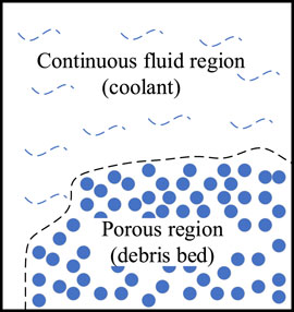
FIGURE 1. Geometry schematic of the porous media.
The Eulerian two-fluid model is used to describe the fluid phase, which consists of mass, momentum, and energy governing equations. The equations are nearly the same for the fluid in the continuous fluid region and porous region. The difference occurs in the effect of the porosity in the porous region. For the solid phase, an additional energy equation is applied to solve the temperature distribution of solid particles.
For the fluid in a continuous fluid region as well in the solid phase, the governing equations are shown below.
1) mass conservation equation
2) momentum conservation equation
3) energy conservation equation
For the fluid in the porous region, the equations are described by adding the influence of porosity
4) mass conservation equation
5) momentum conservation equation
6) energy conservation equation
In addition, the energy equation for the solid phase is described below. It is assumed that the solid phase will not melt or move during the process. Therefore, the mass and momentum conservation equations are neglected.
Based on the basic conservation equations, additional correlations should be provided for the solution of the interfacial mass, momentum, and energy exchange associated with the phenomena. The correlations include the model of flow resistance for the porous media; the heat exchange among the solid, liquid, and vapor phase; and the mass exchange between liquid and vapor. These are discussed in detail in the following sections.
In the multiphase flow, the flow regime is an important parameter in the correlation. In the present study, fluid flow within the porous bed and the clear fluid region is assumed to be divided into three different flow regimes. Depending on the volume fraction of the fluid phases, they are described as the liquid continuous (or bubbly) regime, the transition regime, and the vapor continuous (or droplet) regime. In this paper, the divided rule of Koushik Ghosh (Chakravarty et al., 2020) is used, which is shown in Table 1. In the following correlations, the subscript j refers to the continuous phase, while k represents the dispersed phase.
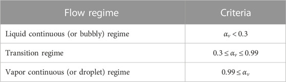
TABLE 1. Determination of flow regimes.
The main source of flow resistance considered in this paper is the interfacial drag force among the three phases and it is different in different regions. For the continuous fluid region, only the interfacial drag force exists between water and vapor, which comes from the velocity difference of the two phases. For the porous region, the drag forces between solid particles and fluids occupy the major fraction of flow resistance other than the interfacial drag force.
1) Continuous fluid region
In the continuous fluid region, the interfacial momentum exchange
In Eq. 2-14, the subscript k refers to the dispersed phase,
The interfacial drag coefficient f is determined by the model of Schiller and Naumann (Schiller and Naumann, 1935), which is widely used in the analysis of the boiling phenomenon. It usually defaults to the model and is adequate for all fluid–fluid phases in the CFD codes (Khan et al., 2020). The expression is shown as Eqs. 2–16.
where the coefficient
2) Porous region
For the porous region, the existing three phases generate three kinds of force, which include the interfacial drag between the solid phase and the saturating fluid phases as well as the interfacial drag between the liquid phase and vapor phase. All drag forces are described by the terms
After a wide literature review, the interfacial drag between the saturating fluid phases is ignored by many researchers except Schulenberg and Muller (Schulenberg and Muller, 1987). These authors considered the interfacial drag force
Compared to the interfacial drag force, the drag forces
where the permeability K and passability η are calculated according to Eq. 1-2. The coefficient of correction
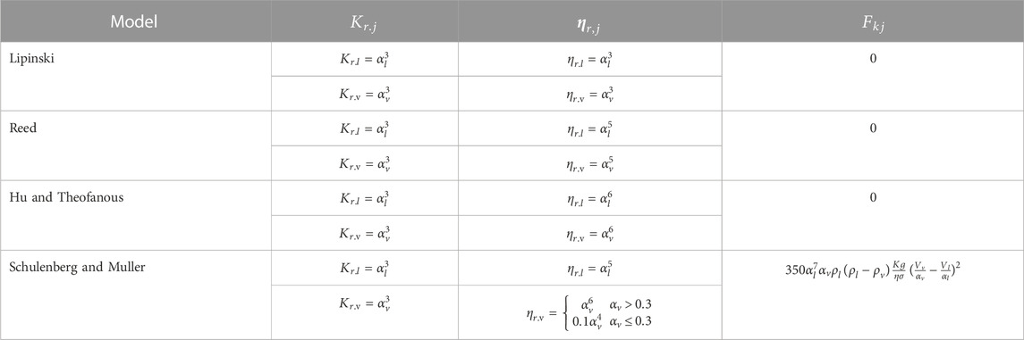
TABLE 2. Coefficient of correction in different models of flow resistance.
According to the conclusion of Weimin Ma (Huang and Ma, 2018), Reed’s model shows the best performance in the validation of frictional pressure drop while Schulenberg & Müller’s model is more suitable for the prediction of DHF. Therefore, it is necessary to conduct another validation for the model of flow resistance in porous media.
During the cooling process after a severe accident, the major heat source is the decay heat from the debris bed. The heat exchange exists among the three phases and different mechanisms are considered. In the continuous fluid region, the interfacial liquid–vapor heat transfer is the main type of heat exchange. In the porous region, the convective heat transfer and boiling heat transfer between the solid and fluid phases should be added as major types of heat exchange. All of these mechanisms are discussed in the following sections with the correlations for the calculations.
1) Continuous fluid region
In the continuous fluid region, the interfacial heat transfer is especially important for the two-phase flow with 0 <
where subscript j refers to the continuous phase and the heat transfer coefficient
For the liquid continuous regime
For the vapor continuous regime
For the transition regime, a linear interpolation between continuous and vapor continuous regimes is used, which is
where W is a factor of weight, which is calculated according to the void fraction and its limitation in Table 1 (Chakravarty et al., 2020).
2) Porous region
For interfacial liquid–vapor heat transfer, the model in the porous region is the same as that in the continuous fluid region. However, it occupies a small fraction of the heat exchange in the porous region. The heat transfer between the solid and fluid phases is a major source and is generated from the decay heat. This heat exchange can be divided to two types: convective heat transfer and boiling heat transfer. Both of these types occur on the surface of the porous debris bed. However, differences exists when the flow regimes vary. The heat transfer is estimated as below
The heat transfer coefficient is determined by using the Ranz and Marshall (Ranz and Marshall, 1952) correlation, which can be expressed as
The coefficient of convective heat transfer mentioned previously is only used for the continuous fluid phase, while
In the transition regime, the heat transfer coefficient is evaluated by a linear interpolation between the nucleate and film boiling regimes using weighing parameter w. The coefficient correlations proposed by Rohsenow (Rohsenow, W.M., 1951) and Bromley (Bromley, L., 1950) are used for nucleate and film boiling. In total, the detailed expressions of convective heat transfer are shown as Eqs. 2–22.
For the coefficient
Except for convective heat transfer, the boiling heat transfer is more important where the influence of latent heat is far more than convective heat transfer in the boiling process. In this paper, the method of the RPI model (Kurul and Podawski, 1991) is used, which is described as
where
Because of the narrow space in the porous region, the quenching heat flux is neglected. For the boiling phenomenon under low pressure, the bubble departure diameter is always 1 mm, which is larger than the scale of flow space in the porous region. Therefore, the action of bubble lift-off and quenching heat flux is suppressed.
The interfacial mass exchange only occurs between the liquid and vapor phases. It is assessed by the boiling heat transfer and interfacial heat transfer. The former value is used for the vaporization and the latter for condensation. The expression is described as
The calculations are conducted based on the commercial computational fluid dynamics platform ANSYS FLUENT. The simplified geometry and boundary conditions are shown in Figure 2. The investigated geometry is simplified to 2D axis-symmetry body, and the axis is set to the X-direction because of the rule of the platform. The bottom and outer wall surface are considered an adiabatic wall, and the upper water surface is set as a constant pressure boundary. The shape of the porous region varies according to the setting, which could be cylindrical, conical, and truncated conical bodies.
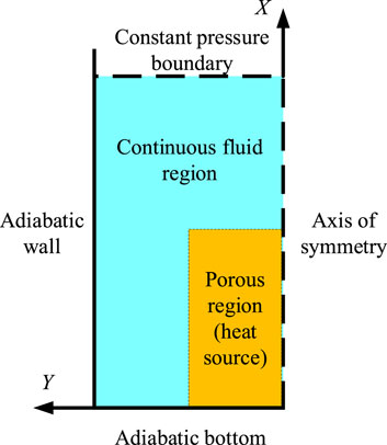
FIGURE 2. Simplified geometry and boundary conditions.
The Eulerian multiphase model is utilized to solve the governing conservation equations. Furthermore, the packed bed method is used to integrate the aforementioned settings. In detail, the porous debris bed is set as a packed bed whose velocity is strictly limited to 0. The volume fraction of the solid phase is set to 1 -
The RPI boiling model is used as the basic method for the calculation of porous media. The heat coefficients among the three phases are utilized and coupled to the corresponding transport equations using the User Defined Functions (UDFs). For the boiling heat transfer in Eqs. 2–23, the models provided by the platform are used directly, which include the Tolubinski–Kostanchuk model (Tolubinski and Kostanchuk, 1970) for the bubble departure diameter, the Cole model (Cole, R., 1960) for the bubble departure frequency, the Lemmert–Chawla model (Lemmert and Chawla, 1977) for the nucleation site density, and the Delvalle–Kenning model (Del and Kenning, 1985) for the area influence coefficient. The symmetric model is used for the interfacial area
In the correlation related to flow resistance, the SST k-ω model is used for the calculation of turbulence in the present study. The integrated drag model of Schiller–Naumann is utilized directly for the continuous fluid region. In the porous region, the additional force
In general, the pressure drop and limited power density (or dryout heat flux) are the key parameters used to validate the accuracy of the developed model (Li et al., 2015). In the porous region, bubbles generate at the whole-body surface and aggregate into the continuous vapor regime. When the void fraction exceeds the limited value, the dryout phenomenon occurs, which causes potential damage to the debris bed. However, the process of bubble aggregation is influenced by the flow resistance. The equilibrium relationship between bubble generation, movement, and aggregation is the main factor used to determine the limited power density.
Before the other validations, a grid-independent calculation was conducted to select the best grid scale. Bed 3 of the DEBECO facility (Li et al., 2015) is used as the test case, which considers isothermal air–water flow. It is simplified as a 2D geometry with 60 mm × 600 mm with a porosity of 0.4 and an effective particle diameter of 1.44 mm. The material properties assumed for the solid phase are taken from Takasuo et al. (Takasuo, E., 2016) (
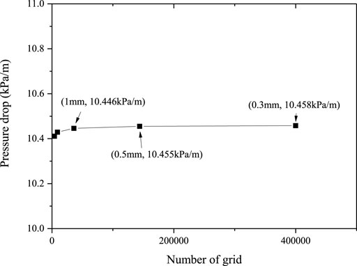
FIGURE 3. Grid-independent calculation of the DEBECO facility.
The pressure drop is the main parameter that reflects the flow resistance. The same bed of the experimental facility (DEBECO, (Li et al., 2015)) is used for the validation. In addition, single-phase and air–water two-phase flow are validated among the experimental data, theoretical results, and CFD calculations. For the single-phase flow, the Ergun model (Ergun, 1952), which is described in Eq. 1-1 is used for the simulation. The comparative results are shown in Figure 4 under different superficial velocities of liquid. The analytic results are obtained by solving Eq. 1-1. The results show good agreement with the relative error under 0.1% for the single-phase flow resistance.
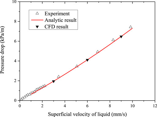
FIGURE 4. Comparison of results for the single-phase flow resistance.
Regarding two-phase flow, the proposed model and loading setting are used for the validation. In the test case, the superficial velocity of liquid is set to 0.147 mm/s and the pressure is approximately 1 bar. All four correlations in Table 2 are validated for the performance. The results of different superficial velocities of air are shown in Figure 5.
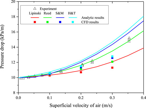
FIGURE 5. Comparison of results for the two-phase flow resistance.
Compared to the experimental data, the analytic result of Reed’s model shows the best performance, while the CFD results of S&M and H&T’s models are proximate. All relative errors are less than 13%, which met the accuracy requirements.
For the validation of heat and mass transfer correlation, a fully flooded porous media from the COOLOCE facility (Takasuo, E., 2016) was used as the integrated case. According to the experimental facility, the scale of the whole zone can be simplified to 306.5 mm × 500 mm. Inside, the porous region is a 2D geometry of 152.5 mm × 269.6 mm, which indicates a cylinder-type porous media. The porosity is set to 0.392, and the effective particle diameter is 0.97 mm. This case operates under 1.3 bars of pressure, which is a bit more than the atmospheric pressure.
During the experimental process, a step-wise heating method is utilized to determine the limited power density. The heating power is set to a relative low value at the initial condition. The internal thermocouples provide feedback for the temperature at the measured points whose growth determines the occurrence of the dryout phenomenon. If no temperature rise is monitored, the heating power increases step-by-step every 5 minutes. Through this method, the measured power level is 34.1 kW in the experiment, while the limited power density is 1728.6 kW/m3.
Based on the ANSYS FLUENT platform, the same method is used in the calculation to determine the limited power density. The initial power density is set to 25% lower than the experimental value. The maximum temperature of the porous media is also monitored at the same time. The limited power density is determined when an obvious increase of temperature occurs. Under the four correlations of flow resistance, the calculated limited power density is shown in Table 3.
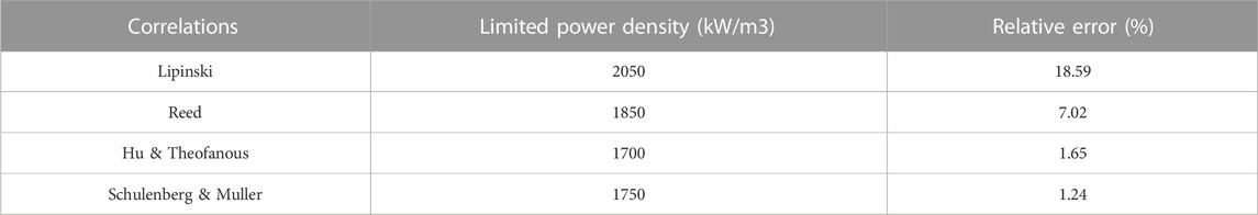
TABLE 3. Limited power density calculated under different flow correlations.
According to the validation mentioned previously, results show that the Schulenberg & Muller drag model has both good performance in the calculation of flow resistance and limited power density. Therefore, it is chosen as the main drag model in the following discussion. The validation also proves a certain accuracy of the proposed method of heat and mass transfer, which is suitable for the analysis of pool boiling in porous media.
In the following discussion, the influence of natural convection, structural parameters, and shape is analyzed based on the proposed model aforementioned. The same fully flooded porous medium from Takasuo’s facility (Takasuo, E., 2016) is used as the main research object in this section. In addition, the determined factor of limited power density is also discussed under different boundary conditions and settings.
The literature review shows that the position where boiling crisis occurs is difficult to determine and a non-general conclusion is provided. The experimental data (Takasuo, E., 2016) showed that the boiling crisis always occurs close to the center of the geometry, while results of the numerical simulation (Chakravarty et al., 2020) indicate that the position was located at the edge of the top surface. Therefore, in this section, the position of the maximum temperature is investigated based on the proposed model.
After comparing the experiment and existing simulation, the heating type was determined as the main difference during the research process. In general, the step-wise heating method is used in the experiment. However, a given value of the heating source is used directly in the simulation. If it is not the limited power density, all settings of the calculation would be initialized before the next step. Figure 6 shows the variation of temperature distribution under two different heating types. Along with the time, the position of maximum temperature suffers a movement from the edge of the top surface to the center under the setting of the direct heating source. However, the maximum temperature appears at the same position under the settings of the step-wise heating source.

FIGURE 6. Time variation of temperature under two heating types.
To investigate the reason of the location migration, Figure 7 and Figure 8 show the void fraction and velocity vectors of liquid and vapor, separately, which are at the same moment as Figure 6. This indicates that the velocity vectors are of great significance in the distribution of the vapor phase and temperature. In the settings of the direct heating source, the bubble moves along the vertical direction under the effect of buoyancy force at the initial time. However, it is difficult to form a strong natural convection because of the low temperature difference and high flow resistance in the porous region. Therefore, the generated bubbles gather at the edge of the top surface, which may lead to a potential boiling crisis. Along with the development of natural convection, the flow toward the center of the porous region is enhanced, which pushes the bubbles to the center. When the bubble aggregation occurs at the center, the high temperature appears as a consequence.
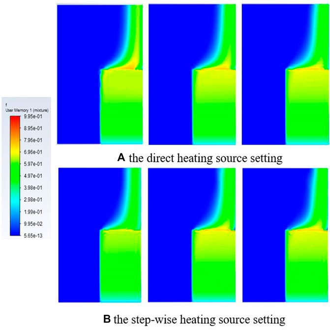
FIGURE 7. Time variation of the vapor phase fraction under two heating types.
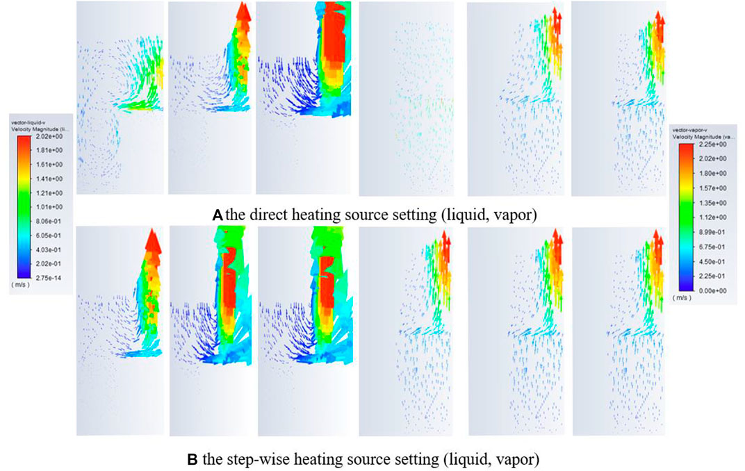
FIGURE 8. Time variation of the velocity vector under two heating types.
The phenomenon is different in the settings of the step-wise heating type. The initial power level is not high enough to result in the dryout phenomenon. However, the waiting time (not less than 5 minutes) is enough to form natural convection at a certain level. When the additional power is added step-by-step, the generated bubbles have a high radius velocity and move to the center of the porous region. Therefore, the bubble aggregation occurs at the center at the first time, which delivers the maximum temperature. Overall, the strengthening of natural convection is the determining factor in the position of the boiling crisis. It is also the reason for the different performance of the two heating types during the process of a realistic severe accident.
Under different boundary conditions, the limited power density may have a large difference. The effects of pressure and structural parameters are investigated in this section. Furthermore, the non-uniform distributions of structural parameters are also studied, which is more similar to the real porous debris bed.
1) Operating pressure
The operating pressure is an important parameter during the process of a severe accident. The realistic pressure of the debris bed may occur in the range of 0.1 MPa to several atmospheres, which depends on the realistic process. Therefore, several conditions should be investigated to study the relationship between limited power density and pressure. Figure 9 shows the trend of limited power density under different pressures, and a linear correlation exists between limited power density and pressure. This trend is also consistent with the experimental value. This again provides confidence in the proposed model with a relative error lower than 5%.
2) Structural parameters
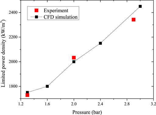
FIGURE 9. Trend of limited power density under different pressure.
The structural parameters discussed in this section refer to the porosity and effective particle diameter after the formation of the debris bed. In the existing literature, uniform distributions are considered for these structural parameters under different conditions. From the view of Solid Geometry, the porosity has a minimum and maximum value if uniform spherical particles are assumed to make contact with each other in all three dimensions. The two contact modes are shown in Figure 10. According to the mathematic calculation, the minimum and maximum porosity are approximately 0.108 and 1–π/6, respectively. Therefore, the range from 0.2 to 0.5 is discussed in the following content. For the effective particle diameter, a test is conducted for the potential range. It is determined that too large of a diameter is not suitable for the discussion because non-limited power density is gained. Therefore, the range from 0.8 mm to 1.1 mm is used to investigate the influence of diameter.
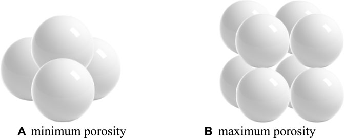
FIGURE 10. Solid geometry of minimum and maximum porosity. (A) minimum porosity (B) maximum porosity
Figure 11 shows the trend of limited power density under different structural parameters. A higher limited power density is affordable when the porosity increases. The analysis of results also shows a great effect on the reduction of flow resistance when the porosity increases. The flow passability of fluid increases under lower flow resistance, which improves the heat transfer coefficient upon the heat surface of the debris bed. It is also difficult for the bubble to accumulate at the top of the porous region, which has a positive influence on the heat removal ability. In addition, the rise is more obvious when the porosity increases from 0.4 to 0.5, which approaches the limited value of porosity. This growth phenomenon is consistent with the results of Koushik Ghosh et al. (Chakravarty et al., 2020). However, a higher porosity than 0.5 is difficult to use in this geometry, and no limited power density is gained based on the proposed model.
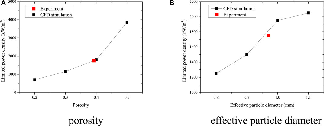
FIGURE 11. Trend of limited power density under different porosity and effective particle diameter. (A) porosity (B) effective particle diameter
Figure 11B shows the effect of particle diameter. During the severe accident process, the entire mass of porous debris remains unchanged. The volume of the debris bed is also the same if the density of reactor corium is assumed constant. Therefore, lower limited power density or worse cooling ability occurs under the condition of smaller particles, which indicates that too many fragments and pellets are formed after the vigorous reaction between corium and the coolant.
3) Non-uniform distribution of effective particle diameter
During the process of a realistic severe accident, multi-scale fragments may exist at different regions, which leads to a variation of structural parameters. Therefore, the non-uniform distributions of structural parameters are also discussed in this section. Simple cases with a difference from the top to bottom are used to investigate the key factor of limited power density. As shown in Figure 12A, the structural parameter in porous region 2 remains 1.0 mm in all cases, while that in porous region 1 varies from 0.9 mm to 1.1 mm. Compared with the value in Figure 11B, the results in Figure 12B show that the limited power density is determined by the structural parameter of the top half geometry rather than the whole region.
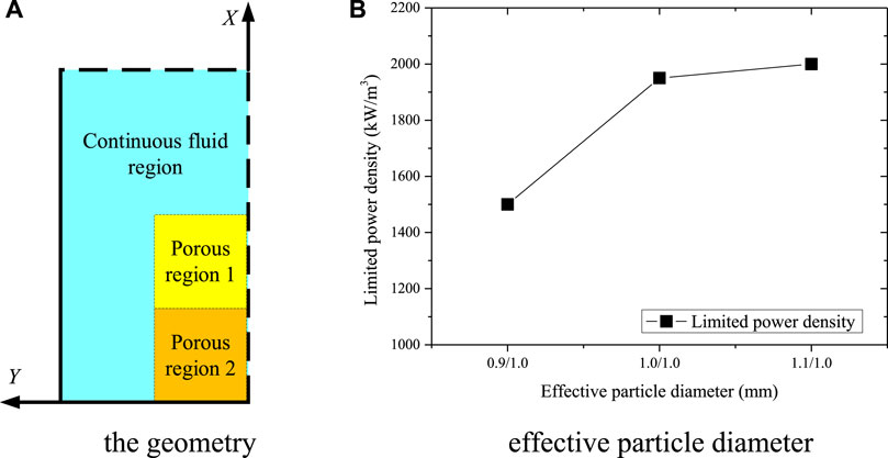
FIGURE 12. Limited power density under non-uniform distribution of the effective particle diameter. (A) geometry (B) effective particle diameter
Porosity is also an important variable parameter in the analysis of the porous debris bed. However, the influence of an inhomogeneous distribution is not easy to investigate through this simulation. In the ANSYS FLUENT platform, the porosity is calculated based on Eq. 4-1, while
Based on the assumption that the whole mass of the reactor corium and its composition are constant, the volume of the entire solid phase would not change during the process of a severe accident. Therefore, the porosity is determined by the volume of space occupied by the debris bed. Furthermore, the shape and volume of the debris bed are investigated in the The Effect of Shape Section, which could also reflect the effect of porosity.
During the process of a severe accident, the kinds of shapes may form based on the reactor corium of the same mass. In this paper, three kinds of heap-like geometry are used for the investigation, which include conical, truncated conical, and cylindrical geometries. During the comparison, the volume of the debris bed is kept constant, which may influence the total decay heat. Figure 13 shows the limited power density under different boundary settings. For the truncated cone, the geometries with the same height, same bottom radius, and same top radius are investigated. For the conical geometry, the debris bed with same height is discussed, while the height of the case with same bottom radius is higher than the total scale. In addition, the cylindrical geometry with a downcomer is also discussed in this section. The comparison of limited power density is shown in Figure 13.
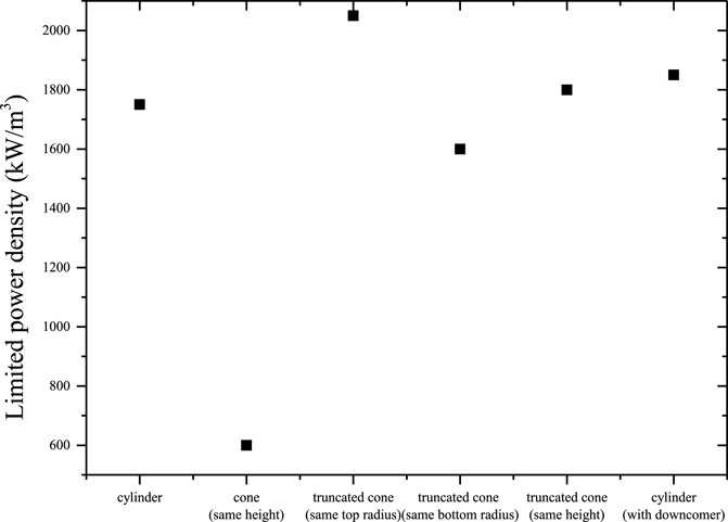
FIGURE 13. Comparison of the limited power density under different shapes of the debris bed.
In summary, the conical geometry has a minimum limited power density, which is far lower than the others and can be explained by the aggregation of bubbles in the tip area. Figure 14 shows the distribution of temperature and void fraction. The maximum temperature appears in the top of the conical geometry, which is also the remelting start position. The cylinder with the downcomer has a stronger cooling ability than that of the other geometries. As a result, the volcanic type with a downcomer is safer during the realistic process. Compared with the results of different geometries with the same height, we can also determine that the height is not a unique factor to determine the limited power density, even though the boundary conditions and structural parameters are kept the same.
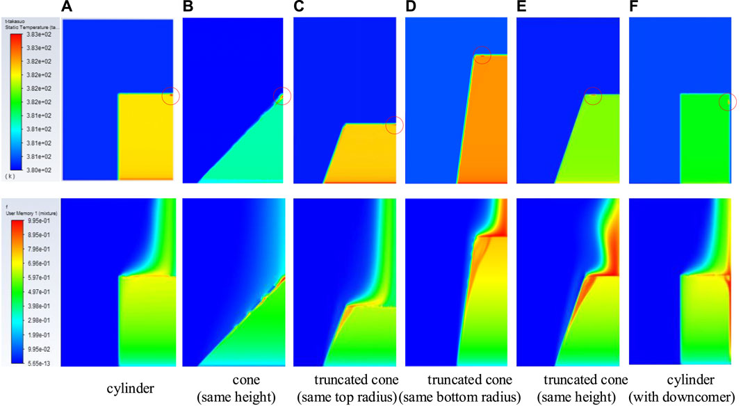
FIGURE 14. Distribution of temperature and void fraction of different geometries.
To investigate the cooling ability of a porous debris bed after a severe accident, the two-phase conservation equations with closure correlations are proposed for the inside pool boiling phenomenon. All calculations are conducted based on the CFD method. The analysis and discussion are around the effect of heating type, non-uniform distribution of structural parameters, and the shape of geometry. The results show the key effect of natural convection between the different boundary settings of the heating type. The time series of strong natural convection formation and decay power heat are the determined factor for the position of the boiling crisis. In addition, the limited power density is determined by the top half of the debris bed. The increase in the structural parameters and operating pressure lead to a better cooling ability. For the shape of the debris bed, a regular cylinder is a better structure for heat removal, while the conical shape significantly reduces the limited power density, which is dangerous for the long-term cooling of the debris bed. Overall, the cooling ability would be better if a downcomer existed in the porous debris bed.
The raw data supporting the conclusion of this article will be made available by the authors without undue reservation.
CRediT authorship contribution statement: JX: software and writing—original draft. XD: conceptualization, methodology, and writing—review and editing. HZ: review, funding acquisition. XY: writing—review and editing. LZ: methodology and supervision. YY: analysis and software. XL: analysis and software. JM: analysis and software. MY: methodology and review
This work was Supported by the National Key R&D Program of China (Grant no. 2018YFB1900100) and Guangdong Basic and Applied Basic Research Foundation (No. 2021A1515110922).
JX, HZ, XY, and LZ are employed by the China Nuclear Power Technology Research Institute.
The remaining authors declare that the research was conducted in the absence of any commercial or financial relationships that could be construed as a potential conflict of interest.
All claims expressed in this article are solely those of the authors and do not necessarily represent those of their affiliated organizations, or those of the publisher, the editors, and the reviewers. Any product that may be evaluated in this article, or claim that may be made by its manufacturer, is not guaranteed or endorsed by the publisher.
Barleon, L., and Werle, H. (1981). Dependence of dryout heat flux on particle diameter for volume- and bottom-heated debris beds. Tech. Report. Kernforschungszentrum Karlsruhe, KfK 3138.
Chakravarty, A., Datta, P., Ghosh, K., Sen, S., and Mukhopadhyay, A. (2020). Characteristics of thermal energy removal from heat-generating porous media considering liquid-vapour phase change. Int. J. Heat. Mass Transf. 148, 119073. doi:10.1016/j.ijheatmasstransfer.2019.119073
Cole, R. (1960). A photographic study of pool boiling in the region of the Critical Heat Flux. AICHE J. 6, 533–538. doi:10.1002/aic.690060405
Del, V. V. H., and Kenning, D. B. R. (1985). Subcooled flow boiling at high heat flux. Int. J. Heat. Mass Tran. 28, 1907–1920. doi:10.1016/0017-9310(85)90213-3
Gourbil, A., Fichot, F., Prat, M., Quintard, M., and Duru, P. (2019). Experimental study of the dryout of a 2D heat-generating model porous medium. Exp. Therm. Fluid Sci. 107, 140–145. doi:10.1016/j.expthermflusci.2019.05.011
Hofmann, G. (1984). On the location and mechanisms of dryout in top-fed and bottom-fed particulate beds. Nucl. Technol. 65, 36–45. doi:10.13182/nt84-a33371
Hu, K., and Theofanous, T. G. (1991). On the measurement and mechanism of dryout in volumetrically heated coarse particle beds. Int. J. Multiph. Flow. 17 (4), 519–532. doi:10.1016/0301-9322(91)90047-7
Huang, Z., and Ma, W. M. (2018). Validation and application of the MEWA code to analysis of debris bed coolability. Nucl. Eng. Des. 327, 22–37. doi:10.1016/j.nucengdes.2017.11.038
Khan, I., Wang, M. J., Zhang, Y. P., Tian, W., Su, G., and Qiu, S. (2020). Two-phase bubbly flow simulation using CFD method: A review of models for interfacial forces. Prog. Nucl. Energy 125, 103360. doi:10.1016/j.pnucene.2020.103360
Kulkarni, P. P., Rashid, M., Kulenovic, R., and Nayak, A. (2010). Experimental investigation of coolability behaviour of irregularly shaped particulate debris bed. Nucl. Eng. Des. 240, 3067–3077. doi:10.1016/j.nucengdes.2010.05.020
Kurul, N., and Podowski, M. Z. (1991). “On the modeling of multidimensional effects in boiling channels,” in Proceedings of the 27th National Heat Transfer Conference, Minneapolis, USA.
Leininger, S., Kulenovic, R., Rahman, S., Repetto, G., and Laurien, E. (2014). Experimental investigation on reflooding of debris beds. Ann. Nucl. Energy. 74, 42–49. doi:10.1016/j.anucene.2014.07.007
Lemmert, M., and Chawla, L. M. (1977). “Influence of flow velocity on surface boiling heat transfer coefficient in Heat Transfer in Boiling,” in Academic press and hemisphere. Editors E. Hahne, and U. Grigull (New York, USA: Academic Press).
Li, L. X., Zou, X. M., Lou, J. J., Li, H., and Lei, X. (2015). Pressure drops of single/two-phase flows through porous beds with multi-sizes spheres and sands particles. Ann. Nucl. Energy. 85, 290–295. doi:10.1016/j.anucene.2015.05.025
Reed, A. W. (1982). The effect of channeling on the dryout of heated particulate beds immersed in a liquid pool. Ph.D. thesis Cambridge, USA: Massachusetts Institute of Technology).
Rohsenow, W. M. (1951). A method of correlating heat transfer data for surface boiling of liquids. Technical Report. Cambridge, Mass: MIT Division of Industrial Cooporation.
Schiller, L., and Naumann, Z. (1935). A drag coefficient correlation. Z. Des. Vereins Dtsch. Ingenieure 77, 318–320.
Schulenberg, T., and Muller, U. (1987). An improved model for two-phase flow through beds of coarse particles. Int. J. Multiph. Flow. 13 (1), 87–97. doi:10.1016/0301-9322(87)90009-7
Takasuo, E. (2016). An experimental study of the coolability of debris beds with geometry variations. Ann. Nucl. Energy. 92, 251–261. doi:10.1016/j.anucene.2016.01.030
Tolubinski, V. I., and Kostanchuk, D. M. (1970). “Vapor bubbles growth rate and heat transfer intensity at subcooled water boiling,” in 4th International Heat Transfer Conference, Paris, France.
Trenberth, R., and Stevens, G. F. (1980). An experimental study of boiling heat transfer and dryout in heated particulate beds. Winfrith: UKAEA Atomic Energy Establishment.
Wang, M. J., Wang, Y. J., Tian, W. X., Qiu, S., and Su, G. (2021). Recent progress of CFD applications in PWR thermal hydraulics study and future directions. Ann. Nucl. Energy 150 (2021), 107836. doi:10.1016/j.anucene.2020.107836
F Momentum exchange
l Liquid
v Vapor
p Particle
s Solid
w Wall
j Continuous phase
k Dispersed phase
c Convective heat transfer
b Boiling heat transfer
Keywords: porous media, cooling ability, natural convection, limited power density, numerical simulation
Citation: Xu J, Dong X, Zhang H, Yun X, Zhang L, Ye Y, Liu X, Mo J and Yang M (2023) Numerical investigation of cooling ability in heat-generating porous debris bed after severe accident in PWR. Front. Energy Res. 10:1097736. doi: 10.3389/fenrg.2022.1097736
Received: 14 November 2022; Accepted: 16 December 2022;
Published: 12 January 2023.
Edited by:
Jun Wang, University of Wisconsin-Madison, United StatesReviewed by:
Yandong Hou, Northeast Electric Power University, ChinaCopyright © 2023 Xu, Dong, Zhang, Yun, Zhang, Ye, Liu, Mo and Yang. This is an open-access article distributed under the terms of the Creative Commons Attribution License (CC BY). The use, distribution or reproduction in other forums is permitted, provided the original author(s) and the copyright owner(s) are credited and that the original publication in this journal is cited, in accordance with accepted academic practice. No use, distribution or reproduction is permitted which does not comply with these terms.
*Correspondence: Xiaomeng Dong, ZG9uZ3hpYW9tZW5nQHN6dS5lZHUuY24=; Huiyong Zhang, emhhbmdodWl5b25nQGNnbnBjLmNvbS5jbg==
Disclaimer: All claims expressed in this article are solely those of the authors and do not necessarily represent those of their affiliated organizations, or those of the publisher, the editors and the reviewers. Any product that may be evaluated in this article or claim that may be made by its manufacturer is not guaranteed or endorsed by the publisher.
Research integrity at Frontiers
Learn more about the work of our research integrity team to safeguard the quality of each article we publish.