- 1School of Control Science and Engineering, Shandong University, Jinan, China
- 2Yangzhou Huading Electric Co., Ltd., Yangzhou, China
This paper proposes a four-port soft open point (FSOP) with photovoltaic (PV) and battery energy storage systems (BESS) and its optimization strategy and control technology. Combining PV output, BESS characteristics, peak and valley electric charges, transformer operation efficiency, and soft open point (SOP) characteristics, the operation criteria under different operating conditions are formulated to improve the economy of the distribution network. In this paper, the power distribution optimization algorithm is established based on the transformer consumption characteristic model and the equal consumption incremental rate criterion to improve the power utilization rate and the system’s economy. The system doesn’t require an additional central controller and transmits control signals through the DC link of FSOP to realize the coordinated operation of all ports. The simulation results show that the system and the optimization strategy can realize the system’s coordinated operation and improve the distribution network’s economy.
1 Introduction
The increasingly diversified load and power demand make the AC distribution network have great problems in safety, reliability, economic applicability, and distribution efficiency (Ji, 2019). With the adjustment of the energy structure and the development of the power system, distributed PV, BESS, and new power electronic equipment are more and more widely used in the power system, which makes the distribution network have more abundant and active regulation capability. Among them, SOP, as a fully controlled power electronic device, has attracted the attention of many scholars.
Access to distributed PV and BESS effectively alleviates the problem of resource shortage and large load fluctuation of the distribution network (Conti, 2012; Bloemink, 2013; Rueda, 2013). However, when they are connected to the distribution network, they are all planned, designed and operated independently, there is a lack of coordination between the systems, as well as the problem of converter redundancy, which leads to a decrease in the economy and stability of the system. At the same time, the periodic characteristics of PV power generation and the periodic changes of power load make the power flow size and direction of the distribution network change at any time. Therefore, the low-voltage distribution network suffers from large fluctuations in transmission power, difficulties in ensuring transformer operating efficiency, high operating costs, and difficulties in matching power generation and consumption (Verzijlbergh, 2014; Huang, 2015). It is not easy to ensure the economic applicability and distribution efficiency of low-voltage distribution networks.
The power distribution-oriented SOP has flexible, fast, and accurate power exchange control and power flow optimization capabilitiy (Chen, 2020; Wang, 2022; Zhou, 2022), and can realize the integrated coordination and optimization management of “Generation-Grid-Load-Storage” (Jeffrey, 2013; Wang, 2016b; Zeng, 2016). It enables the AC distribution network to balance safety and reliability, economic applicability and distribution efficiency (Wang, 2017; Kashani, 2019; Wang, 2020). Wang (2016a), Xue (2020), and Li (2021) studied the optimal operation and cooperative control strategy of flexible distribution network based on SOP. And the results show that SOP can improve the system power flow and reduce system loss. Wang (2017) studied the SOP siting and capacity fixing problem, and the research results showed that the reasonable configuration of SOP can effectively improve the economy of distribution network. The research on multi-port control of SOP of Huang (2019) and Wu (2019) shows that stable DC link voltage is a prerequisite for stable operation of multi-port system containing SOP, and that with SOP control, the system can achieve power flow between multiple port.
Many scholars have studied the optimal operation of systems containing SOP and proved the effectiveness of SOP in the optimal operation of distribution networks. However, most of the studies are focused on the location of SOP and the setting of BESS capacity. There is little research on the connection mode and collaborative control of PV, BESS, and SOP. The optimization of the operation of the transformers connected to the SOP is also rarely considered.
Based on the above research and analysis, this paper proposes to connect PV and BESS to the SOP’s DC link to form a FSOP. Compared with the independent grid connection of distributed power sources, FSOP can save cost by reducing the number of converters and replacing multiple small capacity BESSs with one large capacity BESS. On the premise of comprehensive consideration of PV output, the efficiency characteristics of transformers, and peak and valley electric charges, this paper proposes a novel power distribution optimization algorithm. The algorithm uses the power regulation function of SOP to realize the cooperative operation of multiple converters, and establishes an optimization model to improve the economy and stability of the distribution network. In the power distribution optimization algorithm, an optimal scheduling method based on equal consumption incremental rate criterion is established to improve the economy and stability of the system. In the multi-converters collaborative control strategy, the DC link of FSOP is used as the signal transmission path to realize the cooperative control of each unit without the central controller. Finally, the effectiveness of the proposed optimization method is verified by Matlab/SIMULINK.
2 The structure of four-port soft open point for distribution network with photovoltaic and battery energy storage systems
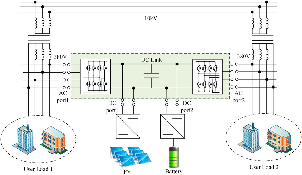
In this paper, we propose a four-port soft open point, as shown in Figure 1. Two AC ports are directly connected to the distribution network. Two DC ports are led from the DC link of the FSOP and connected to PV and BESS. As shown in Figure 1, the device is connected to two transformer rooms of the distribution network and connected to PV and BESS to form a small distribution network system. The system connects the four ports through a DC link to achieve power flow and regulation between the four ports, creating a hardware foundation for power transfer in time and space (Miu, 2012). In combination with the policy of peak and valley electric charges, the operation strategy is formulated to realize the coordinated operation of each unit, improve the operation efficiency of the system and the economic benefits.
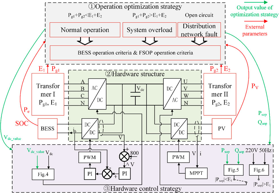
The system mainly includes transformers, FSOP, PV, BESS, user load, and etc. PV output is limited by natural resource conditions, which can be regarded as a relatively uncontrollable power supply to provide certain power support for the system. BESS is connected to the FSOP through a bidirectional DCDC converter, and can change the working state by adjusting the operation strategy to realize the load transfer in the time scale. Transformers can be regarded as the main power supply of the system, and the operation efficiency can be improved by adjusting the load rate. FSOP can change the working mode by changing the control strategy to realize the transfer of load at the spatial scale (Wang, 2013). The overall control architecture of the system is shown in Figure 2.
As shown in Figure 2, the part ① divides the system into different operation states. Then, according to PV output and the state of BESS, the optimal operation criteria is executed and the control signals are generated. The part will be described in detail in Section 3. The part ② represents the hardware structure of the four-port SOP proposed in this paper, which is the carrier of control and optimization operation strategies. The part ③ realizes the control of the four converters in the system based on the control signals generated by the part ①.First, FSOP controls the operation of the two AC/DC converters according to the control signal generated by the operation optimization strategy, and then controls the other two DC/DC converters according to the voltage of DC link. Among them, 220 V and 50 Hz represent the standard value of mains voltage, and 800 represents a reference value, which can determine the control strategy of BESS by comparing with V. The Section 4 will describe this part in detail.
3 System optimization layer
The system has four ports, which are connected through a DC link. This connection creates the basis for energy flow between the ports. At the same time, the coupling between each unit is enhanced and the difficulty of cooperative operation is increased. In order to realize the cooperative operation of each converter and realize the optimal scheduling of PV, BESS, and FSOP, it is necessary to formulate the optimal operation strategy of the system (Cao, 2016; Ding, 2011; Li, 2015; Zeng, 2016; Zhang, 2020; Zhao, 2015).
3.1 Operation criteria
The purpose of formulating optimization strategy is to realize the stable and economic operation of the system by adjusting the operation state of each unit. Therefore, it is necessary to define the operation criteria of each unit first and then determine the system’s overall operation strategy according to each unit’s operational criteria. The operation criteria of BESS, PV, FSOP, and the equal consumption incremental criterion of the transformer will be introduced below.
To distinguish the operation state of the system, the following definitions are made in this paper. Transformer overload state means that the output power of the transformer exceeds the rated capacity. System overload state means that the total output power of two transformers exceeds the total rated capacity. Normal operation state means that the system is not overloaded.
3.1.1 Battery energy storage systems operation criteria
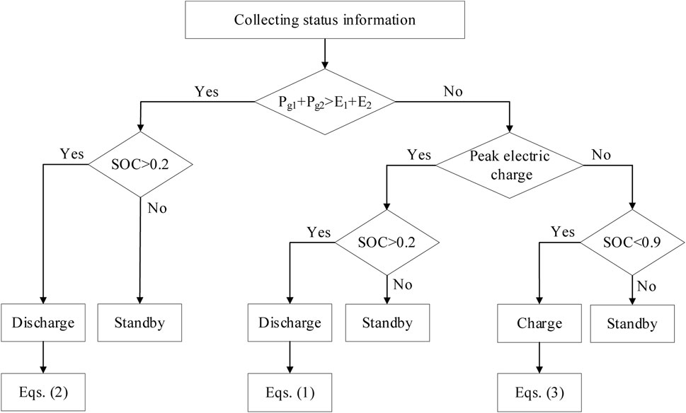
BESS can transfer power consumption across time scales to reduce load fluctuations in distribution network and reduce operating costs. Therefore, this paper proposes a BESS charging and discharging operation criterion based on the state of charge (SOC), electricity price, and transformer overload state, as shown in Figure 3.
Where, Pe represents the actual charging and discharging power of BESS, Pcnmax represents the maximum charging and discharging power of BESS. PLi and Ei respectively represent the user load and the rated capacity of the transformer on side i, and PV represents the power generated by PV.
3.1.2 PV operation criteria
PV in the system can be regarded as a relatively uncontrollable auxiliary power supply, which can provide a certain power support for the system. Considering the system’s economy, PV adopts maximum power point tracking control strategy.
3.1.3 FSOP operation criteria
When distribution network fault occurs, the FSOP operates in VdcQ-Vf control mode. At this time, FSOP does not perform active power regulation and only maintains stable power supply on the fault side. In the system overload state, when one transformer overload, the FSOP operates in VdcQ-PQ control mode for active power regulation to reduce the load rate of the overload side transformer and improve the system’s stability. When two transformers overload, FSOP will not conduct active power regulation. In the normal operation state, FSOP determines the power value to be regulated according to the power distribution optimization algorithm. The algorithm is based on the equal consumption incremental rate criterion of the transformer.
3.1.4 Equal consumption incremental rate criterion of transformer
The two transformers in the system are connected with the distribution network as the main power supply of the system. According to the efficiency characteristics and load rate characteristics of the transformer, the consumption characteristic model of transformers is established. And then, the load distribution of the system is optimized through the equal consumption incremental rate criterion of the transformer to improve the operation efficiency of the transformer. The consumption characteris-tics and power inequality constraints of the two transformers are as follows:
The derivative of the above equation is used to obtain the incremental characteristics λ1 and λ2 of the two transformers, thus establishing the constraint conditions as follows:
where Fi, Pgi, Poi, Ei and Pki are respectively the input power, output power, no-load loss, rated capacity and short circuit current of transformer i. Solve Fi and Pgi satisfying (4) and (5).
3.2 System optimization operation strategy
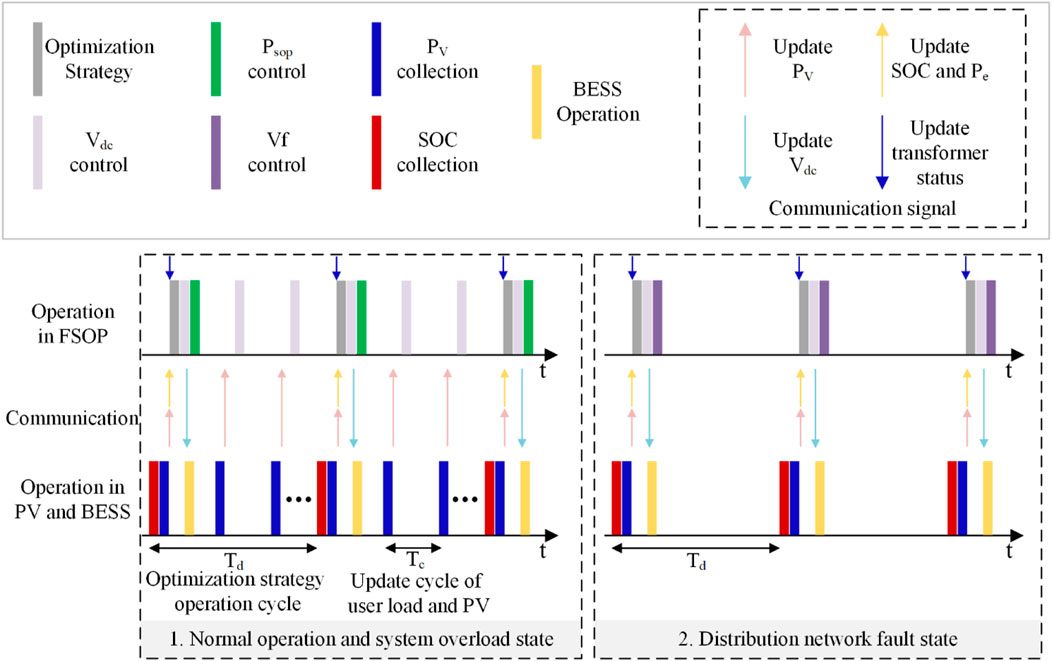
As shown in Figure 2, the system includes three states. In order to realize the stable and economic operation of the system, this paper proposes different operation strategies for different system states, and the optimization time series of system states is shown in Figure 4.
3.2.1 Normal operation state
At the normal operation state, the economic operation of the system is taken as the optimization objective, where the optimization objective can be described as:
where C represents the total electricity costs of the distribution network, Pin (t) and c (t) represent the input power and electricity price of transformers in the period t respectively, cbess represents the electricity cost per kilowatt hour of BESS, and Pbess represents the total charge and discharge of BESS. And μi (t) means the efficiency of transformer i at time t.
At a certain time, user load, electricity price, and PV output in the system are fixed. Therefore, the system’s economy can only be improved by adjusting the charging and discharging power of the BESS and improving the operating efficiency of transformers. To this end, this paper proposes a new optimized operation strategy based on BESS and FSOP. First, FSOP collects signals and determines the charging and discharging power Pe according to BESS operation criteria and determines the net load of the system at the current time. Then, the output power of the transformers on both sides is determined according to the power distribution optimization algorithm, and then the power value and flow direction on the DC link are determined. Finally, the control signals are generated. The operation optimization time series is shown in Figure 4.
As shown in Figure 4, the optimization strategy operation cycle is Td, that is, before the next Td, the control strategy of each converter in the system will not change, and the DC link voltage and the output power of BESS will not change. Only when the next Td comes, FSOP will collect SOC, the output power of PV and BES. At the same time, FSOP will collect the current load rate of transformers, and then execute optimization strategy to generate new control signals, thereby changing the control strategy of each converter. Among them, BESS operation, Psop control and Vdc control shown in Figure 4 have been introduced in Section 3.1.
3.2.2 System overload state
At the system overload state, to ensure the safe and stable operation of the system, the operation strategy shall be adjusted to make the transformer operate within the allowable range of rated capacity or reduce its overload. In this state, BESS constantly discharges at the maximum power, and the output control signal Vdc_value is 850. When one side transformer is overloaded (assuming that the load rate of transformer 2 is higher), FSOP conducts active power regulation to reduce the overload rate of transformer 2. At this time, the output control value Psop_value meets (8).
When both transformers are overloaded, FSOP does not conduct active power regulation and only distributes the output power of PV and BESS according to the overload degree of transformers on both sides. First, calculate the power value that needs to be supplemented to the high load rate side when β1 = β2 is met, record the value as Pdo, and then distribute the remaining power according to the condition that the load rates on both sides are the same. The output control value Psop_value meets (9). The operation optimization time series is shown in Figure 4.
3.2.3 Distribution network fault state
At the distribution network fault state, the system uses the fault isolation function of FSOP to realize uninterrupted power supply of load at the fault side. The FSOP performs VdcQ-Vf control to maintain the fault side voltage and frequency stability, and PV and BESS provide power support for the system. The operation optimization time series is shown in Figure 4.
4 Equipment control layer
In the system optimization layer, after FSOP determines the optimization strategy and outputs control signals based on the system state, it is necessary for each unit in the system to work together to realize the economic and stable operation of the system. Since the system involves four converters, in order to transmit the control signal generated by the system optimization to each converter, this paper proposes a control method without a central controller to achieve the coordinated control of each unit in the system.
The operation optimization strategy is implemented in FSOP, so FSOP can directly control both AC/DC converters after outputting control values Vdc_value and Psop_value. However, the converter on the BESS side cannot directly obtain the control signal and needs to be transmitted through the signal path. While PV operates under the maximum power point tracking control strategy, it does not need to be regulated by the control signal of the system optimization layer. Therefore, the controlled quantity is single, and the converter on the BESS side can be controlled by transmitting the control signal through the DC link. PV output is greatly affected by the external environment, BESS operation status switches frequently and capacity is limited, which is not suitable for maintaining DC voltage stability. FSOP can realize the stable control of DC voltage, so FSOP maintains constant DC voltage in this system.
4.1 four-port soft open point control
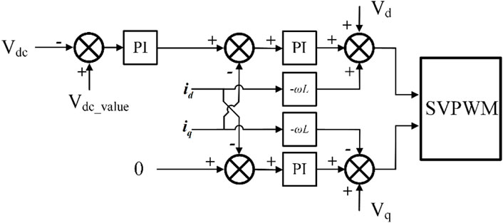
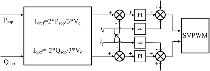
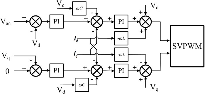
Control signals Vdc_value and Psop_value generated by the operation optimization strategy determine the control mode of FSOP. One converter operates in VdcQ control mode, and the other operates in PQ control mode or Vf control mode (Wang, 2013). As shown in Figure 5, when converter operates in VdcQ control mode, Vdc_value is input into the control loop as the reference signal of the voltage outer loop, and the DC link voltage is controlled through feedback regulation of the PI controller. As shown in Figure 6, when converter operates in PQ control mode, Psop_value and Qsop_value are input into the control loop as reference signals of the power loop, and the power flow is controlled through negative feedback regulation. When converter operates in Vf control mode, in order to achieve stable power supply of three-phase unbalanced load, the positive sequence, negative sequence and zero sequence voltages are respectively controlled by Vf, and their control block diagrams are shown in Figure 7. When controlling the positive sequence voltage, the reference signal Vac takes the amplitude of the mains voltage 311 V, and when controlling the positive sequence voltage and zero sequence voltage, the reference signal Vac = 0. At this time, the converter does not need PLL and the value of frequency f is 50 Hz.
4.2 Battery energy storage systems control
As mentioned above, the control signal needs to be transmitted to the converter on the BESS side through the DC link. During FSOP operation, the DC link voltage within a certain range can maintain the stable operation of FSOP, so BESS can determine its different operation modes and charge and discharge power values through different DC voltage values. For example, in a 380 V distribution network, DC link voltage in the range of 750VDC ∼ 850VDC can maintain the system’s stable operation. When the DC link voltage is 780VDC ∼820VDC, BESS does not work. When the DC link voltage is 820VDC ∼ 850VDC, the BESS is in constant power discharge mode, and the discharge power is (10). When the DC link voltage is 750VDC ∼ 780VDC, the BESS is in constant power charging mode, and charging power is (11).
5 Simulation results
To verify the effectiveness of the optimized operation strategy proposed in this paper, simulation is carried out in Matlab/Simulink. PV output curve measured at Shandong Province is shown in Figure 8A. The peak time, valley time, and electricity price refer to the standards issued by Shandong Province. The electricity price is \0.5769 at 8:00–22:00 and \0.3769 at 0:00–8:00 and 22:00–24:00. And the transformers used in the simulation are S9-50/10 and S9-100/10. To simplify the model, this paper does not consider reactive power. Figure 8B shows the actual user load and the output power curve of the transformer after FSOP optimization, and the user load is set according to the average daily power load curve of Shandong Province released in 2018. The red line in the figure indicates the actual user load on both sides of the system, and the green line indicates the output power of transformers after the optimization strategy. The black dashed line indicates the SOC variation curve of BESS.

FIGURE 8. 24-h (A) PV output curve, (B) user load and transformers output, (C) electricity cost curve.
Figure 8C shows the system electricity cost curve. The PV output and the actual user load are shown in Figure 8A and Figure 8B. The main parameters of BESS are as follows: the maximum capacity is 25 kW h, the maximum power is 7.5 kW, the maximum value of the SOC is 0.9, and the minimum value is 0.2. In Figure 8C, the green line represents the total electricity cost without BESS, the black line represents the total electricity cost without optimization, and the red line represents the total electricity cost after optimization. It can be seen from the figure that the FSOP and its operation strategy proposed in this paper reduce the power consumption cost of the system by about 6% and 3% respectively compared with the traditional distribution network and FSOP without optimal operation strategy. Therefore, FSOP and its operation optimization strategy can improve the economy of the system.
In this paper, the simulation verifies that the converters in the system can achieve cooperative operation under different operating conditions and strategies. Figure 9 shows the waveforms of FSOP, BESS and DC link power when the system generates a new control signal at t = 5 s and the operating state of each port in the system changes. Figure 10 shows the waveforms of the fault-side user load voltage, FSOP, and BESS when the system is switched from the normal operation state to the distribution network fault state. Wherein, Figures 9A, 10A show the DC link voltage, FSOP side converter regulation waveform in 4.8–5.2 s, Figures 9B, 10B shows the waveform of SOC, charging and discharging current, charging and discharging voltage of BESS in 0–10 s. Figure 9C shows the output power value of the system side transformers and the power value regulated through FSOP in 0–10 s. Figure 10C shows the voltage waveform of user load at fault side in case of system fault.

FIGURE 9. (A) DC link voltage and AC/DC converters regulation waveform, (B) State change waveform of BESS, (C) Power variation diagram within the system.

FIGURE 10. (A) DC link voltage and AC/DC converters regulation waveform, (B) State change waveform of BESS, (C) The voltage waveform of the user load on the fault side.
As shown in Figure 9, within 0 ∼ 5 s, the system does not use the power distribution optimization algorithm for optimal regulation. At this time, the DC link voltage is 800 V, the BESS does not work, and the SOC is constant at 60%. At this time, the output and transfer power of transformers on both sides do not change. When t = 5 s, the system optimization layer uses the power distribution optimization algorithm to adjust and control, generate control signals Vdc_value and Psop_value, where Vdc_value is 750, and Psop_value is 69,200, and transmit them to each converter. It can be seen from Figure 2 that when t = 5 s, the DC link voltage is rapidly adjusted to 750 V, and the current waveform of converters on both sides of FSOP quickly tends to be stable after a short time adjustment. The BESS changes the charging state and reaches the maximum charging power in about 0.6 s. Part of the load of transformer 2 is transferred to transformer 1 through FSOP to improve the system efficiency.
As shown in Figure 10, when t = 5 s, the system changed from the normal operation state to the distribution network fault state. At this time, the BESS was discharging with the maximum power, and the unbalanced user load on the fault side was quickly restored to power under the control of the FSOP. The simulation results show that the system can realize the cooperative operation of four ports and the stable power supply of unbalanced load on the fault side without central controller.
6 Conclusion
In order to improve the economy and stability of the distribution network, this paper proposes a FSOP and its optimization strategy and control technology. In this paper, the consumption characteristic model of transformer and the equal consumption incremental rate criterion are established to improve the operation efficiency of transformers. And establish the power distribution optimization algorithm to improve the economy and stability of the system. The system does not need a central controller and only needs DC link voltage to control the equipment in the system.
The optimization strategy proposed in this paper considers only the active load, and the optimization effect is obvious when the load rates of two transformers differ significantly. In future work, the configuration and siting of energy storage capacity for multi-ports SOP will be studied to give full play to the advantages of energy storage and SOP.
Data availability statement
The original contributions presented in the study are included in the article/Supplementary Material, further inquiries can be directed to the corresponding author.
Author contributions
XZ is the main author of the paper and experiment. XG and XZ provide technical support and suggestions, and assist in completing papers and experiments, and help XZ collect data. FG guides XZ to complete the experiment and paper writing, and provides theoretical support.
Conflict of interest
Authors XG and XZ were employed by Yangzhou Huading Electric Co., Ltd.
The remaining authors declare that the research was conducted in the absence of any commercial or financial relationships that could be construed as a potential conflict of interest.
Publisher’s note
All claims expressed in this article are solely those of the authors and do not necessarily represent those of their affiliated organizations, or those of the publisher, the editors and the reviewers. Any product that may be evaluated in this article, or claim that may be made by its manufacturer, is not guaranteed or endorsed by the publisher.
References
Bloemink, Jeffrey M., Timothy, C., and Green, P. (2013). Benefits of distribution-level power electronics for supporting distributed generation growth. IEEE Trans. Power Deliv. 28 (2), 911–919. doi:10.1109/tpwrd.2012.2232313
Bloemink, J. M., and Green, T. C, P. (2013). Benefits of distribution-level power electronics for supporting distributed generation growth. IEEE Trans. Power Deliv. 28 (2), 911–919. doi:10.1109/tpwrd.2012.2232313
Cao, W., Wu, J., Jenkins, N., Wang, C., and Green, T. (2016). Benefits analysis of soft open points for electrical distribution network operation. Appl. Energy 165, 36–47. doi:10.1016/j.apenergy.2015.12.022
Chen, H., Xia, F., Yuan, D., Liu, Y., Chen, L., Qin, X., et al. (2020). Optimal configuration scheme of fast electric vehicle charging station with photovoltaic in DC distribution network. Automation Electr. Power Syst. 44 (16), 53–60. doi:10.7500/AEPS20191219005
Conti, S., Nicolosi, R., Rizzo, S. A., and Zeineldin, H. H. (2012). Optimal dispatching of distributed generators and storage systems for MV islanded microgrids. IEEE Trans. Power Deliv. 27 (3), 1243–1251. doi:10.1109/tpwrd.2012.2194514
Ding, M., Zhang, Y., Mao, M., Liu, X., and Xu, N. (2011). Economic operation optimization for microgrids including Na/S battery storage. Proc. CSEE 31 (4), 7–14.
Haoran, J., Wang, C., Li, P., Ding, F., and Wu, J. (2019). Robust operation of soft open points in active distribution networks with high penetration of photovoltaic integration. IEEE Trans. Sustain. Energy 10 (1), 280–289. doi:10.1109/tste.2018.2833545
Huang, S., Wu, Q., Oren, S. S., Li, R., and Liu, Z. (2015). Distribution locational marginal pricing through quadratic programming for congestion management in distribution networks. IEEE Trans. Power Syst. 30 (4), 2170–2178. doi:10.1109/tpwrs.2014.2359977
Huang, W., Wu, P., Tai, N. L., Ma, Z. J., Yang, L. Q., Zhang, E. J., et al. (2019). Architecture design and control method for flexible connected multiple microgrids based on hybrid unit of common coupling. Proc. CSEE 29 (12), 3499–3513. doi:10.13334/j.0258-8013.pcsee.172163
Kashani, M. G., Mobarrez, M., and Bhattacharya, S., P. (2019). Smart inverter volt-watt control design in high PV-penetrated distribution systems. IEEE Trans. Ind. Appl. 55 (2), 1147–1156. doi:10.1109/tia.2018.2878844
Li, Z., Zhang, F., Liang, J., Yun, Z., and Zhang, J. (2015). Optimization on microgrid with combined heat and power system. Proc. CSEE 35 (14), 3569–3576. doi:10.13334/j.0258-8013.pcsee.2015.14.011
Li, Z., Ye, Y., Wang, Z., Wu, Y., and Xu, H. (2021). Integrated planning and operation evaluation of micro-distribution network based on flexible multi-state switch interconnection. Trans. China Electrotech. Soc. 36 (2), 487–495. doi:10.19595/j.cnki.1000-6753.tces.L90174
Miu, Y., Cheng, H., Gong, X., Wang, L., Yao, L., and Masoud, B. (2012). Evaluation of a distribution network connection mode considering micro-grid. Proc. CSEE 32 (1), 17–23. doi:10.13334/j.0258-8013.pcsee.2012.01.008
Rueda-Medina, A. C., and Padilha Feltrin, A. P. (2013). Distributed generators as providers of reactive power support-a market approach. IEEE Trans. Power Syst. 28 (1), 490–502. doi:10.1109/tpwrs.2012.2202926
Verzijlbergh, R., De-Vries, L., and Lukszo, Z. P. (2014). Renewable energy sources and responsive demand. Do we need congestion management in the distribution grid. IEEE Trans. Power Syst. 29 (5), 2119–2128. doi:10.1109/tpwrs.2014.2300941
Wang, C., Song, G., Li, P., Zhao, J., Wu, J., et al. (2016a). A hybrid optimization method for distribution network operation with SNOP and tie switch. Proc. CSEE 36 (9), 2315–2321. doi:10.13334/j.0258-8013.pcsee.2016.09.001
Wang, C., Song, G., Li, P., Ji, H., Zhao, J., and Wu, J. (2017). Optimal configuration of soft open point for active distribution network considering the characteristics of distributed generation. Proc. CSEE 37 (7), 1889–1896. doi:10.13334/j.0258-8013.pcsee.152649
Wang, C., Song, G., Li, P., Yu, H., Zhao, J., Wu, J., et al. (2016b). Research and prospect for soft open point based flexible interconnection technology for Smart distribution network. Automation Electr. Power Syst. 40 (22), 168–175. doi:10.7500/AEPS20160620009
Wang, C., Sun, C., Peng, K., Li, Y., Wu, Z., et al. (2013). Study on AC-DC hybrid power flow algorithm for microgrid. Proc. CSEE 33 (4), 8–15. doi:10.13334/j.0258-8013.pcsee.2013.04.007
Wang, C., Ji, J., Ji, H., Yu, H., Wu, J., and Li, P. (2022). Technologies and application of soft open points in distribution networks. Automation Electr. Power Syst. 46 (4), 1–14. doi:10.7500/AEPS20210514005
Wang, J., Zhou, N., Chung, C. Y., and Wang, Q. (2020). Coordinated planning of converter-based DG units and soft open points incorporating active management in unbalanced distribution networks. IEEE Trans. Sustain. Energy 11 (3), 2015–2027. doi:10.1109/tste.2019.2950168
Xue, F., Ma, L., Zhu, H., Shi, J., and Qiao, W. (2020). Bi-level programming of distributed generations in flexible distribution network with SOP optimization. Proceeding CSU-EPSA 32 (8), 109–115. doi:10.19635/j.cnki.csu-epsa.000302
Wu, P., Huang, W., Tai, N., Lu, Y., Ni, C., and Zong, M. (2019). Multi-layer coordinated control strategy for island operation of flexible interconnected multi microgrid based on power mutual assistance. High. Volt. Eng. 45 (10), 3101–3111. doi:10.13336/j.1003-6520.hve.20190924009
Zeng, M., Yang, Y., Liu, D., Zeng, B., Ouyang, S., Lin, H., Han, X., et al. (2016). Generation-grid-load-storage” coordinative optimal operation mode of energy internet and key technologies. Power Syst. Technol. 40 (1), 114–124. doi:10.13335/j.1000-3673.pst.2016.01.016
Zhang, B., Tang, W., Cai, Y., Wang, Z., Li, T., and Zhang, H. (2020). Distributed control strategy of residential photovoltaic inverter and energy storage based on consensus. Automation Electr. Power Syst. 44 (2), 86–96. doi:10.7500/AEPS20190305005
Zhao, B., Bao, K., Xu, Z., and Zhang, Y. (2015). Optimal sizing for grid-connected PV-and-storge microgrid considering demand response. Proc. CSEE 35 (21), 5465–5474. doi:10.13334/j.0258-8013.pcsee.2015.21.010
Zhou, N., Zhang, M., Meng, X., Liao, J., Wang, Q., and Luo, Y. (2022). Control and stability analysis of power transmission between microgrids based on back-to-back converter interconnection. Nanjing: Automation of Electric Power Systems. https://kns.cnki.net/kcms/detail/32.1180.TP.20221102.1022.002.html. doi:10.7500/AEPS20220608005
Keywords: PV, BESS, SOP, the consumption characteristic model, the power distribution optimization algorithm, no central controller
Citation: Zhao X, Gao X, Zhou X and Gao F (2023) Optimization strategy and control technology of four-port SOP for distribution network with PV and BESS. Front. Energy Res. 10:1095607. doi: 10.3389/fenrg.2022.1095607
Received: 11 November 2022; Accepted: 28 November 2022;
Published: 19 January 2023.
Edited by:
Hao Tian, University of Alberta, CanadaCopyright © 2023 Zhao, Gao, Zhou and Gao. This is an open-access article distributed under the terms of the Creative Commons Attribution License (CC BY). The use, distribution or reproduction in other forums is permitted, provided the original author(s) and the copyright owner(s) are credited and that the original publication in this journal is cited, in accordance with accepted academic practice. No use, distribution or reproduction is permitted which does not comply with these terms.
*Correspondence: Xingjian Zhao, MjAyMTM0OTQ5QG1haWwuc2R1LmVkdS5jbg==
 Xingjian Zhao
 Xiongying Gao2