 Xuekai Hu
 Liang Meng
 Can Su
- State Grid Hebei Electric Power Research Institute, Shijiazhuang, China
The renewable energy with distributed generation is widely used because of the cleanliness and sustainability. However, when high renewables connect to the grid, the randomness and intermittent of the renewable energy will deteriorate the performance. As the important interface between distributed generations and power grid, the prosumer can contribute to the improvement of the renewable energy penetration if stable and reliable operation of the power supply is realized. The prosumer has multi-type generations, loads and auxiliary converters, where the characteristics interact each other. Moreover, due to the complicated grid states, the prosumer may operate in different conditions. Therefore, the research on the coordinated operation control strategy of the multiple electrical facilities is necessary in the prosumer with high renewables. In this paper, the AC/DC hybrid prosumer is established with multi-type distributed generations, loads and auxiliary converters. The prosumer can operate in normal grid-connected mode and grid-fluctuation mode. In different modes, the cooperation control of the power converter in the prosumer is proposed, which changes according to the grid demands. When over-limited grid voltage and frequency fluctuation are detected in the point of common coupling, the prosumer can switch from normal grid-connected mode to grid-fluctuation mode to provide voltage and frequency support. Finally, the simulation results based on Matlab/Simulink is employed to verify the effectiveness of the proposed control strategy.
1 Introduction
Due to the rapid depletion of fossil fuels and increasingly serious environmental problems, renewable energy sources (RES) have developed quickly (Bollen et al., 2005). Meanwhile, to manage the energy more effectively and flexibly, the renewable energy resources can use distributed generation (DG) to generate electricity, including the renewables, the energy storage (ES) and the micro-turbine for multi-source complementary (Cady et al., 2015; Elavarasan et al., 2020). The DG corelates with the customer demand and other auxiliary converters to form the prosumer. The prosumer needs the management of the generation, the consumption, and the auxiliary converters to effectively utilize the renewables and ensure the stable grid connection (Liu et al., 2020; Zhu et al., 2020). In the recent future, the prosumer may be one of the main forms of the distribution networks.
Currently, the intermittence and fluctuation of renewable energy sources in both the power grid and the prosumer may cause serious problems, including the power unbalance and voltage fluctuation (Yin et al., 2017; Li et al., 2018). Therefore, when the prosumer connects to the power grid, the management is important in dealing with disturbance inside and outside the prosumer. Because the disturbance is from many different reasons, the DGs and auxiliary converters in prosumer should use different operation strategies according to the characteristics of themselves to provide different service for the grid.
For the photovoltaic (PV) generation, the traditional maximum power point tracking (MPPT) control cannot support the voltage and frequency in ac-bus in the prosumer when it is disturbed (Wang et al., 2022). If the voltage and frequency cannot meet the power quality requirement, the prosumer will shut down to avoid deteriorating the ac-bus. At present, the maximum power point quitting (MPPQ) control can be used to reserve a certain PV output margin to provide corresponding support to the grid when the grid or RES fluctuates (Ropp et al., 2016; Wang et al., 2019). This is a rational compromise between economic efficiency of the renewables and the power quality of the grid. Moreover, energy storage is another important component of the prosumer with highly flexible and controllable power, as well as the fast response speed. ES can play a role of peak shaving and valley filling to meet load demand when connects to the grid and can provide uninterrupted power supply for local loads when disconnected with the grid (Boicea et al., 2014) (Ortega et al., 2016). When the prosumer connects to the grid, the stable connection and high utilization of renewable energy is most important. Inevitable voltage and frequency fluctuation is usually observed (Zhou et al., 2019). The prosumer needs to decrease the fluctuation caused by the renewables and varying loads to reduce the negative impact on the power grid (He et al., 2015). In this situation, more types of DGs in the prosumer should change their control strategy and provide ancillary service for the grid to participate in the frequency modulation and peak regulation.
What’ more, when encountering disturbances, prosumers can switch from normal grid-connected mode to grid-fluctuation mode in the extreme case. To solve this problem, other auxiliary converters for interlinking the DC and AC network and power improvement should work with different control strategies in the regulation of the prosumer (Buraimoh and Davidson, 2021). Then, the mode switch of the DGs in the prosumer is needed, which increases the difficulty for the coordinated operation of the prosumer (Liu et al., 2022). Therefore, the research on the coordinated operation control strategy of the converters in different modes is necessary. The management of multiple energy sources, multi-type loads and auxiliary converters is essential in the prosumer, where the facilities need different control modes according to the demand and respective characteristics (Teng et al., 2019; Zhang et al., 2019). In the meantime, the regulable facilities in the prosumer are also increased. Thus, the research on the coordinated operation control of the prosumer with multiple electrical converters in different situation is indispensable.
The energy resources and local loads are multifarious in the prosumer, and most of them connect to the prosumer by power converters, which has the advantages in realizing complex dynamic characteristic (Tian et al., 2020). At present, research on the control strategies of DG to support grid control has caused widespread concern. For renewable energy generations, the sampling converter method is adopted to provide the maximum power point information for other power generations to regulate the RES (Rizwin et al., 2020). The voltage control and current control strategy can be adopted to provide voltage and frequency support for the system, like droop control and virtual synchronous generator (VSG) control (Meng et al., 2019; Liu et al., 2022). In the literatures (Jia et al., 2016) and (Xu et al., 2022), droop control strategy of PV inverters is proposed to provide voltage and frequency support for the power grid. In the meantime, to improve the dynamic performance, the VSG control strategy is employed in the DGs to emulate the synchronous generator’s (SG’s) electromechanical transient characteristics (D'Arco et al., 2014; Yuan et al., 2016; Li et al., 2018). Furthermore, the research on the control strategies for multi-inverters in parallel is also applicable in the prosumer. For the prosumer with several photovoltaic inverters, the sample PV inverter can be employed to provide maximum power point information for other inverters to keep reserve capacity and high utilization (Xie et al., 2014; Hayde et al., 2017). In the literature (Shen et al., 2021), both of the voltage-controlled battery-storage inverter and current-controlled photovoltaic inverter adopt VSG control strategy and can operate in grid-connected mode. Nevertheless, present research usually focuses on the prosumer with two or three DGs and the research on the coordinated control strategy of the prosumer with high renewables and multi-type power generations is limited. For example, in the literatures (Hou et al., 2015; Mortezaei et al., 2015), the prosumer with multiple photovoltaic inverters is established to realize coordinated operation of high renewables and provide voltage and frequency support for the grid while the types of power supply in the prosumer are still not satisfactory. In the literatures (Qiu et al., 2022) and (Capuder et al., 2020), they establish the prosumer with multi-type power generations and the DGs can operate in parallel stably only in normal grid-connected mode. Therefore, the research on the coordinated operation strategy of the prosumer’s multiple generations in different modes still needs further study.
In this paper, the AC/DC hybrid microgrid with high renewables and various energy sources is built. The prosumer can stably operate in different modes, including normal grid-connected mode and grid-fluctuation mode. In normal grid-connected mode, the prosumer will be connected to the power grid. When large voltage and frequency deviation occur in the PCC, the prosumer will operate in grid-fluctuation mode, where more converter-interfaced facilities will provide ancillary service to participate in the voltage regulation. The coordinated control strategy of multiple power converters in the above modes is proposed with necessary operation mode switch. With the proposed method, the prosumer can actively participate in the active support of the grid in multiple situations.
2 The prosumer’s structure with high renewables
The prosumer discussed in this paper includes both AC and DC bus, and this AC/DC hybrid structure is shown in the Figure 1. To deal with different situations brought by the grid state change and RES power fluctuation, the prosumer needs to stably operate in different modes and provide proper ancillary function for the grid. The detailed description of this prosumer system is introduced in this section.
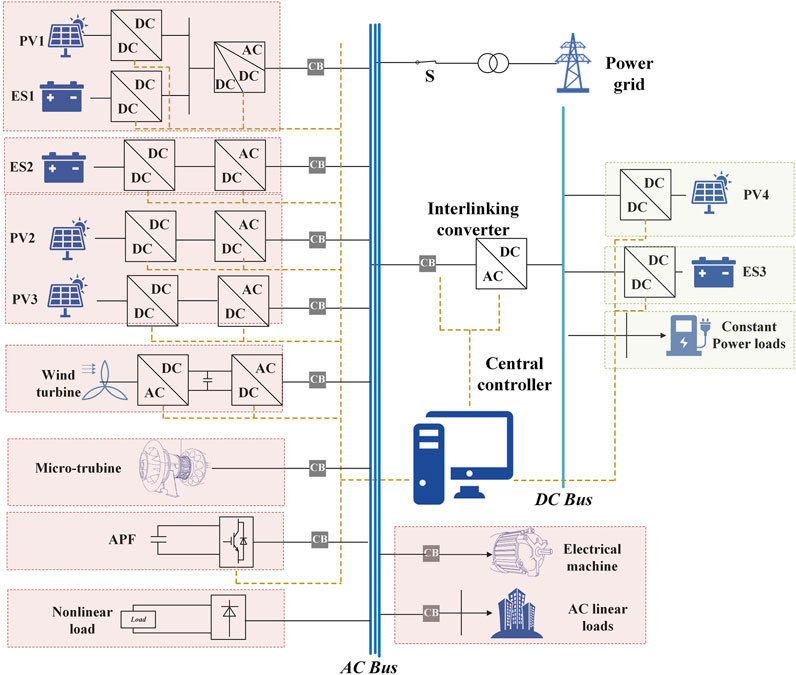
FIGURE 1. The prosumer’s structure.
2.1 Systematic introduction of prosumer
When the prosumer with high renewables connects to the grid, the operation methods should be dependent on the states of renewable energy sources. What’s more, because of the variations of the load power, the voltage in both the DC and AC bus will fluctuate as well. Therefore, the control target is to ensure the stable connection and reduce the impact caused by the renewable energy sources. Therefore, the prosumer should provide voltage and frequency support for the grid and effectively utilize the renewables in the meantime.
The prosumer with high renewables comprising of various energy resources is established. It includes both the AC part and DC part with different types of power supply and load. The DC and AC part is connected to each other with an interlinking converter to balance the power between DC and AC bus. The load in the prosumer is designed multifarious. In the DC part, the constant power load is connected to the dc-bus by the buck converter. The AC system comprises of multi-type power supplies and local loads, including linear load, nonlinear load and electrical machine. Moreover, to enhance the power quality, the auxiliary electrical equipment for power quality improvement is considered. With all of these facilitates, the prosumer established in this paper includes the power supply, load, and auxiliary power converters, which can provide constructive information for the practical system with multi-type power generations with the multiple DGs and loads.
2.2 Multi-type facilities in the prosumer
The prosumer is powered by multiple energy sources. The DC-side subsystem includes a PV generation and a battery-storage generation, which are both connected to the dc-bus by the boost converter. The battery-storage system is used to reduce the fluctuation caused by the fluctuated PV power. The two distributed generations supply power for the constant power loads. In the AC system, the renewable energy sources comprise of the wind power and solar energy. The wind power is feeding to the ac-bus by a back-to-back converter. At the same time, the integrated renewable energy and storage system is connected to the prosumer by the two-stage inverter, which includes two kinds of methods. On the one hand, the only PV panels are connected to the ac-bus only by the two-stage inverter, including the PV2 and PV3. On the other hand, the photovoltaic generation PV1 and the battery-storage ES1 are connected to the DC side of the inverter by the boost converters, which is a two-stage topology. A battery-storage generation ES2 supplies power to the prosumer by the two-stage inverters. Besides, the DGs in the AC part also include the gas turbine with the SG. All the generations mentioned above operate in parallel and constitute the prosumer’s power supply system. The local loads in the AC side consist of linear loads, nonlinear loads and electrical machine. In addition, some auxiliary converters provide the functional management in the prosumer, which includes the active power filter and the interlinking converter.
The prosumer is considered to operate at normal grid-connected mode and grid-fluctuation mode. Considering that the prosumer should deal with different possible situations, the facilitates in prosumer should operates in different modes. As power converters are widely used in the prosumer, he facilities with converter are controlled to flexibly operate in different modes to support the requirement, and hence, the prosumer can provide the AC-bus voltage support and supply power to the loads independently.
3 Control modes of generations in prosumer
The structure and targets of the prosumer are introduced in the last chapter. To realize stable operation and grid support, the coordinate control of the generations is necessary. Before that, in this chapter, the control strategies of the DG, load, and auxiliary converters with different operation modes are introduced.
3.1 RES-integrated converter
As introduced in the chapter 2, the renewable energy sources are deployed in both DC part and AC part of the prosumer including wind turbine and PV panels. The wind turbine is connected to the ac-bus by the back-to-back converter with the asynchronous machine. The grid-side converter is employed to stabilize the DC link voltage and realize unity power factor operation, while the generator-side converter is used for the control of the output active power and the output voltage. In the DC part, the PV panel is connected to the dc-bus by the boost converter, while the PV generations in AC part are connected to the prosumer by the inverters as shown in the Figures 2, 3. The control strategies of the PV converters are discussed in detail in this section.
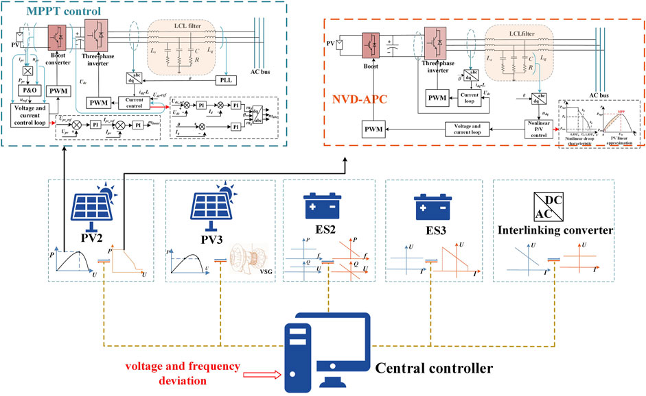
FIGURE 2. The control diagram of PV2.
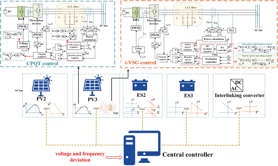
FIGURE 3. The control diagram of PV3.
3.1.1 Maximum power point tracking control
The relationship between the output voltage and output power of PV cell is nonlinear with a maximum power point according to the photovoltaic characteristics that will change with the temperature and the illumination. Therefore, the P&O MPPT control strategy is realized in the boost converter (Hamidon et al., 2012). The detailed implementation of the control loop is illustrated in the Figure 2. The PV inverter adopts current control to stabilize the voltage on the inverter’s DC side, and the control diagram is shown in the Figure 2. The voltage on the inverter’s DC side will follow up the command value Udc_ref. In this control mode, the PV inverter is synchronized with the grid by a phase-locked loop (PLL) and is employed as the current source in the prosumer, which is also a grid-following control method.
3.1.2 Constant active and reactive power tracking control
When the PV inverter adopts MPPT control strategy, the energy utilization is the most effective. However, this method has the weakness in power adjustment, power reserve and power curtailment. When the power fluctuation occurs in the grid, the PV inverter can’t adjust its output power to support the system. Hence, the constant active and reactive power tracking (CPQT) is used as one of the control modes to solve this problem (Liu et al., 2015). The PV inverter adopting CPQT control strategy usually operates under its maximum power point and can change its output power according to the instruction from the central controller. The detailed control method is as follows.
The PV inverter in CPQT control mode stabilizes the voltage on the inverter’s DC side by the boost converter and the control target is realized by the single voltage control loop as shown in the Figure 3. Firstly, the output voltage and current in the PCC Uabc and Iabc-g should be transferred from abc coordinates to dq coordinates to calculate the output power based on the frequency information of Uabc from the PLL. The power-calculating formula is shown below.
where P is the output active power, Q is the output reactive power, Ud is the d-axis voltage, Uq is the q-axis voltage, Id is the d-axis current, Iq is the q-axis current. Then the inverter adopts power and current control loop to realize the CPQT control. The control loop is shown in the Figure 3. In the external power loop, the difference between the reference value and the actual output power is given to the proportional integral (PI) controllers, whose results is used for the calculation of the reference value of the inverter’s output current based on the power-calculating formula. Then the inner loops will realize current command tracking by PI controllers.
3.1.3 Nonlinear-voltage-droop active power control
Droop control is usually used as a kind of voltage control method when grid support is needed. In traditional droop control methods, voltage support is provided based on the active and reactive power regulation. However, these methods usually neglect the ability in active power control in RES-based converter’s control. To solve the problem, the droop control in PV converter is proposed, where a new nonlinear droop based active power control (NVD-APC) method is proposed to further improve the performance. The PV output power is limited by the MPP, and the solar energy might be wasted adopting linear control method. Meanwhile, the constant droop coefficient will lead to the poor voltage-supporting performance when the voltage deviation is too large. Therefore, the NVD-APC method changes the output active power according to the voltage deviation based on the nonlinear P/V droop characteristic shown in the Figure 2. In the nonlinear droop control mode, the output of the PV inverter decreases with the increase of the voltage in AC bus. When the voltage is much higher than the nominal value, the droop coefficient will be increased to accelerate the power reduction. On the contrary, when the voltage is too low, the PV inverter will operate at the maximum power point. The control method is illustrated in the Figure 2. The nonlinear droop control is realized in the boost converter. Firstly, the voltage deviation will be used for the calculation of the reference value of the inverter’s output active power based on the nonlinear P/V droop characteristic. The relationship can be described by the Eq. 2.
where Pref is the reference value of the PV inverter’s output active power, Pmppt is the maximum power of the PV cell, Ud is the amplitude of the PCC voltage, Un is the rated voltage, Pn is the inverter’s rated output active power, kp1 and kp2 are the droop coefficient. Especially, kp2> kp1>0.
Then based on the maximum power point from a pre-set sampling battery, the linear approximated curve of the PV characteristics is used to calculate the reference value of the PV cell’s output voltage (shown in the Figure 2). The boost converter realizes the output power control by regulating the PV output directly and the equation is shown in Eq. 3. Moreover, the minimum output power Pmin depends on the minimum PV output voltage decided by the maximum transformation ratio of the boost converter.
where Uref is the reference value of the PV output voltage, Pref is the reference value of the PV output power, kpv is coefficient of the linear approximated curve of the PV characteristics, Pmppt is the maximum power of the PV cell, Um is the PV output voltage at maximum power point.
With the information of Uref, the boost converter adopts voltage and current control loops to realize voltage tracking as shown in the Figure 2. The inverter’s control method is the same as that in MPPT control.
3.1.4 I-VSG control mode
The inverters adopting current-controlled VSG (i-VSG) control strategy are regarded as the current source, which synchronize with the grid by PLLs. In this control mode, the VSG control emulates the SG’s primary voltage and frequency regulation characteristics by adding droop characteristics and virtual inertia to the control loop (Fan et al., 2021). The output of the SG emulation control part in i-VSG is the reference value of the output power and the central control equations are shown in Eqs 4, 5 with the illustration in the Figure 3.
where Qref and Pref are the reference value of the inverter’s output reactive power and active power respectively, Qn and Pn are the nominal power of the inverter, Un is the inverter’s nominal output voltage, ωn is the inverter’s nominal angular frequency, Ud is the inverter’s output voltage, ω is the inverter’s angular frequency derived from the PLL, J is the virtual inertia.
Therefore, based on the calculation results of the output power reference, the inverter in i-VSG control mode can realize power command tracking with a similar power and current control loop used in the CPQT control (shown in the Figure 3). At the same time, the boost converter’s control strategy is the same as that in CPQT control. Compared to NVD-APC method, the PV generation adopting i-VSG control can provide voltage and frequency support by emulating the SG’s characteristics, where the power adjustment is realized in the inverter. What’s more, in this control modes the virtual inertia is introduced to improve the frequency dynamics of the system.
3.2 Integrated renewables and storage inverter
The integrated renewables and storage inverter consist of the PV source and the battery-storage, whose main circuit is shown in the Figure 4. The PV cell and the battery are connected by two separated DC/DC converters, where the boost converter adopts MPPT control strategy. Then the reference value Upv_ref will be incorporated into the voltage and current loop shown in the Figure 4 to change the PV output power. The battery adopts the single voltage control loop to keep the stable voltage on the inverter’s DC side. When the maximum power of PV cell is larger than the output power of the inverter, the battery will absorb the surplus power with the bi-directional power conversion. On the contrary, when the power can’t meet the inverter’s power reference, the battery will supply power to the system. The inverter shown in the Figure 4 adopts voltage-controlled VSG (v-VSG) control strategy (Wang et al., 2021). The control diagram is also illustrated in the Figure 4. The inverter emulates the SG’s characteristics based on the Eqs 4, 5 introduced in the Section 3.1.4. The reactive power and voltage control equation is shown below.
where Qn is the nominal reactive power of the inverter, Q is the inverter’s output reactive power, Un is the nominal voltage of the inverter, E is the reference value of the inverter’s output voltage, Dq is the droop coefficient of the reactive power and voltage control loop, kq is the integral coefficient of the reactive power and voltage control loop.
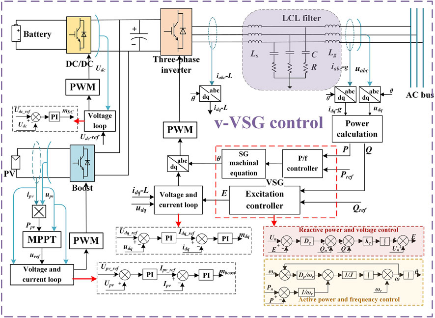
FIGURE 4. The control diagram of the integrated inverter.
At the same time, compared to the droop control, the active power and frequency control in VSG control introduces virtual inertia for the improvement of the frequency dynamics in the Figure 4. The governing equation is as the below equation.
where Pn is the nominal active power of the inverter, P is the inverter’s output active power, ωn is the nominal angular frequency of the inverter, ω is the inverter’s angular frequency, Dp is the droop coefficient of the active power and frequency control loop, J is the virtual inertia. Based on the voltage and frequency information calculated in the above two equations, the inverter adopts the voltage and current control loop to control the output voltage.
3.3 Battery-storage converter
In the prosumer, the battery storage is applied in both the DC part and AC part as shown in the Figures 5, 6. In the DC part, the battery is connected to the dc-bus by the bi-directional DC/DC converter, which works in the droop control mode and constant-voltage mode. The control modes of battery-storage inverter include PQ control and droop control, while the control strategy of PQ control mode is same as the method introduced in the Section 3.1.2. The control diagram of ES2 is shown in the Figure 5.
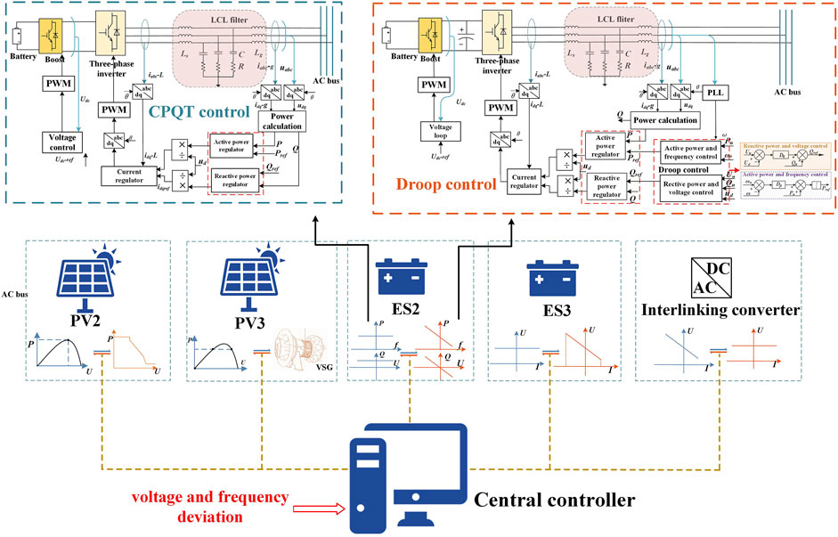
FIGURE 5. The control diagram of ES2.
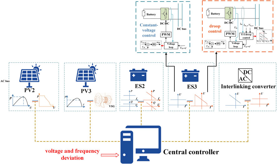
FIGURE 6. The control diagram of ES3.
3.3.1 Droop control in DC part
The droop control can used for the limitation of the voltage deviation in dc-bus caused by the fluctuation of the PV output power. There is droop relationship between the dc-bus voltage and the ES’s output power which can be expressed by the Eq. 8.
where PES is the output of battery-storage converter, Udc is the dc-bus voltage, U0 is the rated value of dc-bus voltage, P0 is the rated output power, β is the power and voltage droop coefficient. Meanwhile, the relationship between the output current and the power can be written below.
where IES is the battery-storage converter’s output current. Hence, by simplifying the above two equations, the voltage and current droop characteristic can be written as the following equation, where k is the voltage and current droop coefficient and I0 is the ES’s rated output current. The droop relationship is illustrated in the Figure 6.
When the voltage Udc is too high and the PV output power is surplus, the charging current of the battery-storage will be increased to lower the voltage. Conversely, when the output power can’t meet the demand and the voltage is lower than the rated value, the battery-storage converter will increase the discharging current. The droop control is realized by the voltage and current control loop shown in Figure 6, where the reference output voltage is calculated based on the droop characteristic.
3.3.2 Droop control in AC part
The droop control strategy of battery-storage inverter is shown in the Figure 5, which is also a two-stage inverter. The boost converter is still used for the DC voltage support and droop control is realized in the three-phase inverter. The control principle of droop control is the i-VSG control, which calculates the active power and reactive power reference value based on the relationship between the output power and voltage vector. The droop characteristics can be written as Eq. 11.
where Qn and Pn are the rated value of the inverter’s output reactive power and active power respectively, Qref and Pref are the output power of the inverter, Un is the inverter’s rated output voltage, ωn is the inverter’s rated angular frequency, Ud is the inverter’s output voltage amplitude, ω is the inverter’s angular frequency.
Based on the active power and reactive power reference value calculated by the droop characteristics, the inverter will realize the output power control by the power and current control loop which is shown in the Figure 5. The battery-storage inverter will regulate its output power when there is fluctuation in the system. When the prosumer works in normal grid-connected mode, the inverter will supply its rated power, while its output voltage is decided by the voltage in PCC. Moreover, the inverter will increase its output active power with the frequency reduction in PCC. And when the voltage in PCC is lower than the rated value, the output reactive power will be increased to support the voltage.
3.4 Micro-turbine
The micro-turbine is introduced in the prosumer as the distributed generator for other energy, which has the advantage in the improvement of the stability and dynamic performance. The micro-turbine in this paper consists of the gas turbine, synchronous generator and control system and operates in the constant power and voltage control (CPVC) mode to keep the output voltage and power stable. The control system includes speed control, mechanical torque control and acceleration control. The speed control is used to keep the SG’s rotating speed stable which is realized by the speed control loop and fuel control loop. At the same time, the mechanical torque control is used to meet the power demand of the SG. Besides, the acceleration control is introduced to avoid too large thermal impact during drastic changes by adding acceleration feedforward control in the fuel control loop. Meanwhile, the control of excitation system is to regulate the excitation voltage to keep the amplitude of stator voltage stable.
3.5 Auxiliary power converters
In the prosumer, beside of the converters employed in the DGs, the auxiliary converters, including interlinking converter and active power filter, also provide necessary service to support the grid.
3.5.1 Interlinking converter
The interlinking converter in the prosumer is one bi-directional DC/AC converter used for the connection of the DC part and AC part can operate in two modes. The converter will work in rectifier operation mode when the output power of the PV generation and battery-storage generation can’t meet the demand of the loads. By contrary, the converter will transfer the extra power to the AC part as an inverter. The control modes of the DC/AC converter are similar to the ES in DC part. When it adopts constant-voltage control, the converter is employed to keep the DC link voltage at the reference value by the current control loop which is the same as the inverter’s control strategy used in the MPPT control (shown in the Figure 7). When it works in droop control mode, the droop characteristic is similar to the characteristic introduced in the Section 3.3.1. The control loops are illustrated in the Figure 7. The droop control also realizes voltage command tracking by the current loop which is used in MPPT control. The difference is that the reference value of the DC voltage is calculated based on the droop equations.
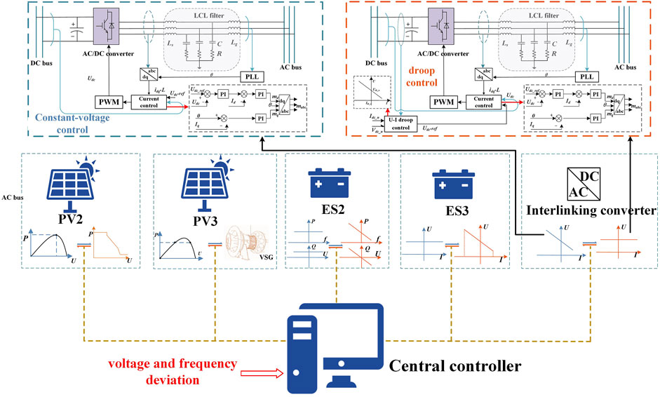
FIGURE 7. The control diagram of the interlinking converter.
3.5.2 Active power filter
As nonlinear loads in the prosumer will deteriorate the power quality, the APF is used to eliminate the current harmonics and improve the power quality. The control diagram is shown in the Figure 8. The current of the nonlinear loads is used for the fundamental component calculation based on the orthogonal characteristic of trigonometric function. Then the harmonic component is obtained by subtraction of fundamental component from original current signal. This component will be the reference output current of the inverter. The current control is realized by the single current control loop. Therefore, the APF will output the harmonic current to eliminate the influence of the nonlinear loads.
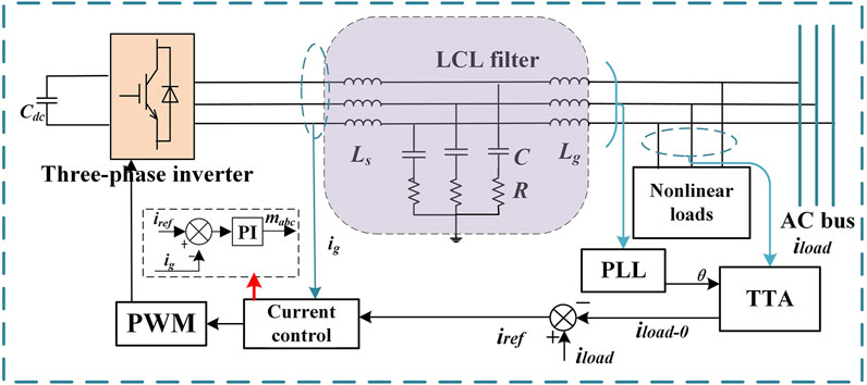
FIGURE 8. The control diagram of APF.
3.6 Multi-type loads
There are multi-type loads in the prosumer. In the DC part, the constant power loads are connected to the dc-bus with the buck converters to keep the power constant. The output voltage of the buck converter is maintained at a constant value to keep the power constant. In the AC part, the loads include linear load, nonlinear load and electrical machine. The linear load is composed of linear elements including resistance, inductance and capacitance and in nonlinear load the linear elements are connected to the ac-bus by the three-phase non-controlled rectifier, which will generate odd harmonics. The electrical machine in the prosumer is the permanent magnet synchronous motor.
4 Prosumer mode switch control
The prosumer can operate in different modes, including normal grid-connected mode and grid-fluctuation mode. The control strategy of the DGs in prosumer will change according to the system demand. In this chapter, the operation modes of the prosumer will be introduced.
4.1 Mode classification
As introduced before, two kinds of main operation modes are considered in the prosumer. When the prosumer is connected to the power grid, the voltage in the ac-bus will be decided by the grid voltage in the bus. The prosumer can exchange power with the grid. When the slight oscillation is occurred in the grid, a part of the DGs in prosumer can provide voltage and frequency support for the grid. In this mode, the primary control objective is to ensure the stable connection of the DGs and guarantee reasonable profit. In the meantime, the enough reserve capacity of the prosumer is also necessary. When the grid voltage fluctuates in a wide range with the significant change of the power distribution, the prosumer should switch from normal grid-connected mode to grid-fluctuation mode. Compared to normal grid-connected mode, more DGs will participate in the voltage regulation. The number of the facilities that provides auxiliary service for the grid will be increased. The prosumer in this control mode will effectively contribute to the fluctuation reduction of the voltage and frequency in the bus.
4.2 Control of multi-type generations in different modes
With the change of the prosumer’s operation objective, the control modes of the DGs will be changed (listed in Table 1). Both in the two kinds of operation modes, multiple equivalent controlled voltage-sourced generators are paralleled in the AC bus of prosumer. The integrated renewables and battery-storage inverter is worked in v-VSG control mode and the output voltage is equal to the grid voltage in PCC. Under normal conditions, the voltage in PCC will be equal to the rated value. Therefore, the inverter will supply rated power to the system. The micro-generator will supply constant power and its output voltage will be unchanged. The PV inverters and battery-storage inverter adopt current-controlled control method. PV2 adopts MPPT control, while PV3 and ES2 both work in CPQT control mode. In DC part, the PV generator works at the maximum power point and the battery will operate in constant-voltage control mode. In this mode, the interlinking converter adopts droop control to reduce the DC voltage fluctuation.
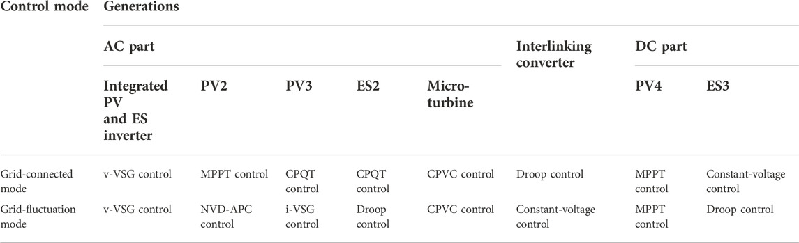
TABLE 1. Control strategies of the DGs in different modes.
In the grid-fluctuation mode, more generators will provide voltage and frequency support. The PV2 will adopt NVD-APC control to support the grid voltage in PCC. The i-VSG control and droop control strategy are employed in PV3 and ES3, respectively. Both inverters will take part in the frequency modulation and peak regulation. What’s more, the integrated PV and ES inverter, and PV3 that adopts VSG control will contribute to the improvement of the frequency dynamics. At the same time, the interlinking converter adopts constant-voltage control to reduce the impact on the PCC voltage. The battery- storage in the DC part will take the voltage-regulation by adopting droop control.
4.3 Mode switch control strategy
As introduced before, when the prosumer switches from normal grid-connected mode to grid-fluctuation mode, the control strategy of several converters should be changed. The mode-switching diagram is shown in the Figures 2,3,5–7. The central controller will receive the fluctuation signal detected in PCC. If the fluctuation is out of a limit for some time, the prosumer will start mode-switching process and the switch signal will be transferred to the converters that includes the PV inverters, the ES inverter, the interlinking converter and the ES generator in DC part. In grid-fluctuation mode, PV2 switches from MPPT control mode to NVD-APC control mode. The control loops of the two strategies are the same, while the power control is realized by the boost converter and the inverter is used to stabilize the DC voltage in both modes. Therefore, when the converters receive the mode-switching signal, the boost converter only needs to change the reference-calculation algorithm from P&O algorithm to NVD-APC algorithm. The control diagram is shown in the Figure 9. The switch S will be thrown from point1 to ponit2. Similarly, the mode-switching process of PV3, interlinking converter and ES3 is realized by changing the reference-calculation step through the switches. For PV3, the central controller introduces the SG characteristics emulation part to calculate the reference power as shown in the Figure 3. In the meantime, the constant reference value of the active power and reactive power of ES2 will be replaced by the calculation results based on the Eq. 11. The reference DC voltage of the interlinking converter will be replaced by the constant value, while the droop characteristic will be introduced in the battery-storage converter reference calculation (shown in the Figures 6,7).
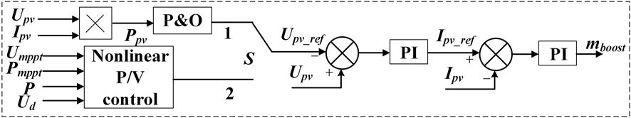
FIGURE 9. The control diagram of the mode switch of PV2.
5 Network simulation of prosumer with multi-type generations
In this section, the simulation based on Matlab/Simulink is used to verify the effectiveness of the proposed coordinated operation strategy in the prosumer with multi-type generations. The prosumer can stably operate in different modes and the seamless mode switch is also realized. The structure of the prosumer is shown in the Figure 1 and the control modes of the multiple generations are introduced in the Table 1 in detail. The simulation parameters are listed in the Table 2.
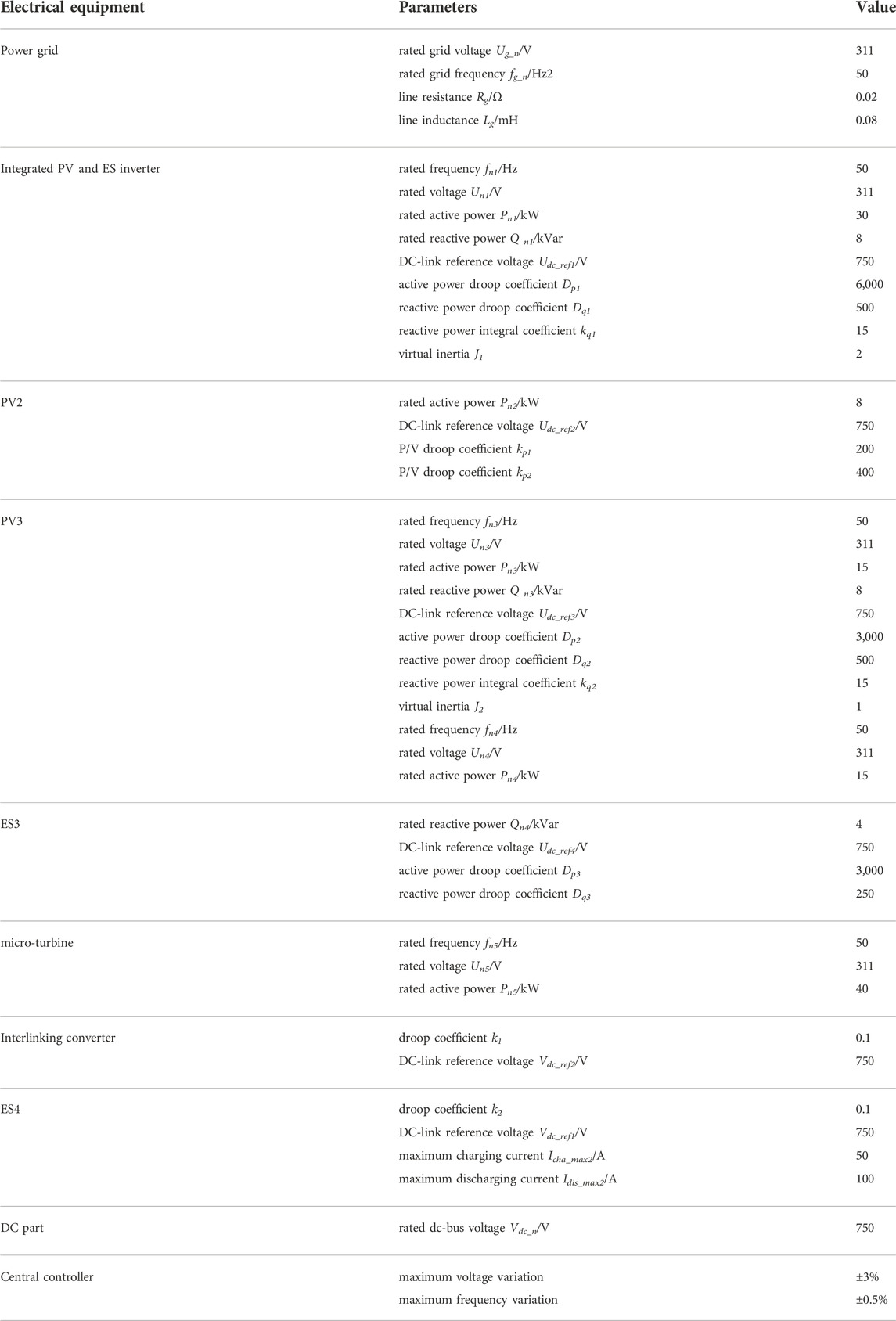
TABLE 2. Simulation parameters.
5.1 Normal grid-connected mode
The control modes of the prosumer’s generations in normal grid-connected mode have been introduced in the last section and are listed in Table 1. In this mode, the output voltage and current of the integrated PV and ES inverter will keep stable and their output voltage will be decided by the grid voltage.
The waveform of the voltage and current in PCC is shown in the Figure 10A. At 2s, the light intensity of PV1 is decreased and the maximum power is changed as shown in the Figure 10B. The power fluctuation of PV1 is eliminated by ES1 and the DC link voltage keeps stable, where the output power of PV1 is represented by PPV1 and the DC link voltage is represented by Udc1. When t = 3.5s, the linear load in the prosumer increases and the light intensity of PV1 and PV2 is reduced, which will lead to the voltage reduction in the ac-bus. As introduced in Section 3.2, the integrated renewables and battery-storage inverter increases its output reactive power to support the voltage at 3.5s. The simulation result is shown in the Figure 10C, where the output active power and reactive power of the integrated PV and ES inverter are represented by P1 and Q1 respectively. The maximum power of PV1 and PV2 is changed as shown in the Figure 10D, where PPV2 represents the output power of the PV2 and the output voltage and current of the PV2 inverter are represented by Um2 and Im2 separately.
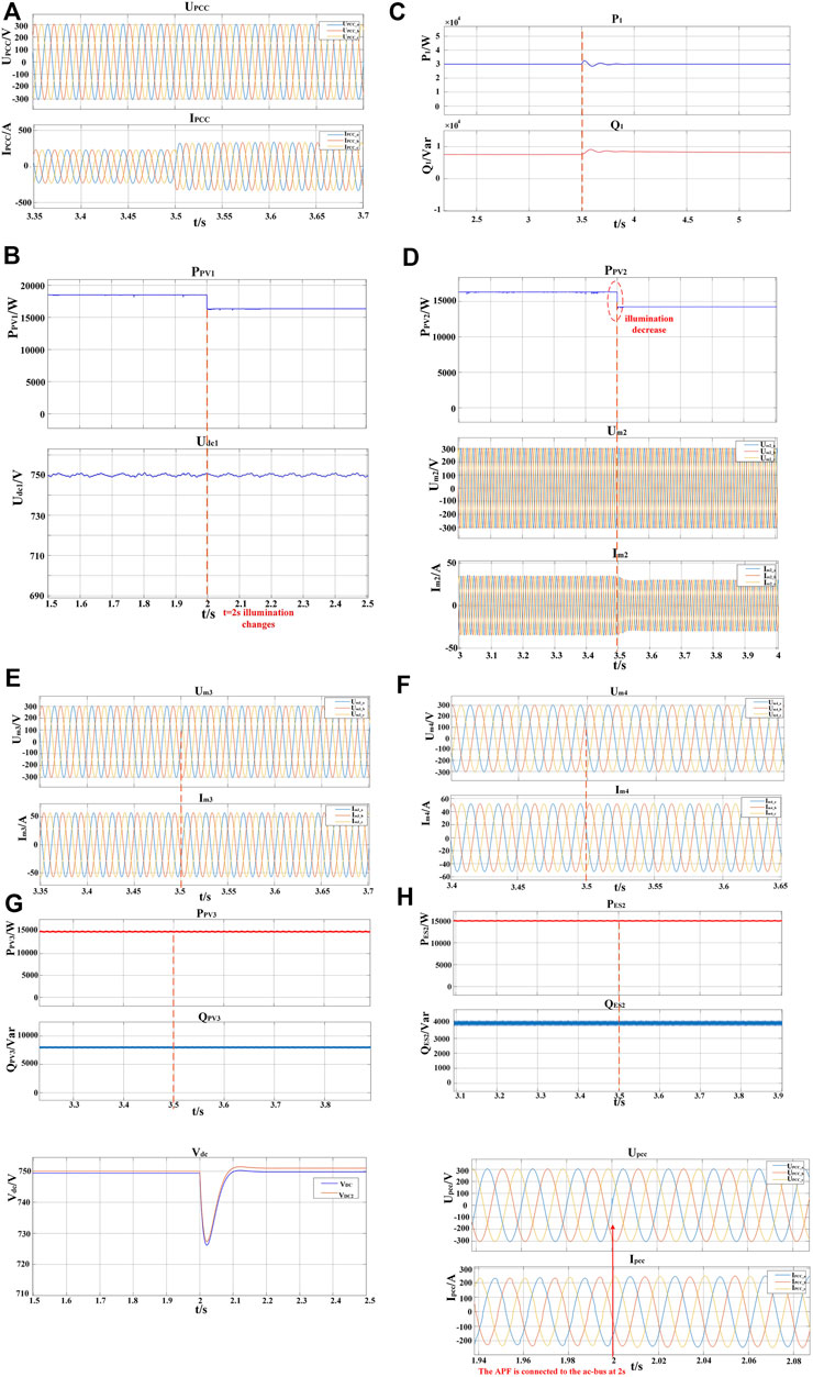
FIGURE 10. The output of the converters in the prosumer in normal grid-connected mode: (A) Voltage and current in PCC; (B) PV1’s output power and the DC link voltage; (C) Output power of the integrated inverter; (D) Output of PV2; (E) Output of PV3; (F) Output of ES2; (G) The comparison between the DC link voltage of the interlinking converter and the voltage in dc-bus; (H) The voltage and current in PCC.
At the same time, the output power of the generations in CPQT control mode will keep unchanged and the results are shown in the Figures 10E,F, where the output power of PV3 and ES2 are represented by PPV3 Q PV3 and PES2 QES2 respectively. The output voltage and current of PV3 inverter are represented by Um3 and Im3 and the output voltage and current of ES2 inverter are represented by Um4 and Im4. In the DC part, the battery-storage converter works in constant-voltage control mode and its output voltage Vdc1 keeps at the rated value. The PV4 adopting MPPT control keeps working at the maximum power point. In grid-connected mode, the interlinking converter adopts droop control and operates as the rectifier. What’ more, at 2s, the local load in the DC part is increased and the reference DC voltage of the interlinking converter is increased to reduce the voltage variation according to the droop characteristic shown in the Figure 7. The simulation result is shown in the Figure 10G, where the voltage in dc-bus is represented by Vdc and the DC link voltage of the interlinking converter is represented by Vdc2. In addition, the effectiveness of the proposed APF is verified in the Figure 10H. When t = 2s, the APF is added to the prosumer and the harmonics of the voltage and current in PCC of the prosumer is effectively eliminated at 2s.
As shown in the simulation results, the prosumer with multi-type generations can operate in normal grid-connected mode stably under the proposed coordinated control strategy. Moreover, when there is fluctuation in the prosumer caused by load variation and illumination change, the integrated renewables and battery-storage inverter can regulate its output power to provide frequency and voltage support.
5.2 Grid-fluctuation mode
In grid-fluctuation mode, more generations will provide auxiliary service for the system and the control modes of the generations are introduced in Table 1. The waveform of the voltage UPCC in PCC is shown in the Figures 11A,B, where Ud_g is the voltage amplitude of UPCC. At 3s, there’s deviation between the grid voltage in PCC and the rated value, while the voltage is restored to the rated value at 7.5s. As introduced in the Section 4.2, there are four generations in the AC part participate in the frequency modulation and peak regulation. When t = 3s, the output active power of PV2 is increased as shown in the Figure 11C, where PPV2 represent its output active power. The integrated inverter, PV3 and ES3 all improve their output reactive power to support the voltage and the simulation results are shown in the Figures 11D–F. In addition, the droop coefficients of the three generations are proportional to their capacities to ensure the proportional variations of their output power. At 7.5s, the fault is cleared, and the output power of the above generations returns to rated value. Furthermore, to verify the frequency-supporting function of the inverters, in the Figures 11G–I the frequency is increased to 50.3 Hz at 3s. The integrated inverter, PV3 and ES2 reduce their output active power to provide frequency support for the grid.
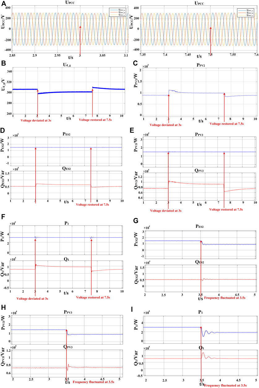
FIGURE 11. The output of the DGs in the prosumer in grid-fluctuation mode: (A) The voltage in PCC; (B) The amplitude of the voltage in PCC; (C) The output active power of PV2; (D) The output active power and reactive power of ES2; (E) The output active power and reactive power of PV3; (F) The output active power and reactive power of the integrated inverter; (G) The output active power and reactive power of ES2; (H) The output active power and reactive power of PV3; (I) The output active power and reactive power of the integrated inverter.
Hence, the effectiveness of the prosumer’s grid-supporting function is verified by the simulation results. Compared to normal grid-connected mode, more generations adopt grid-supporting control strategy, and the power quality can be effectively improved in grid-fluctuation mode.
5.3 Simulation validation of mode-switching control strategy
The mode-switching control strategy proposed in the Section 4.3 is verified by simulation results in this section. The waveform of the grid voltage in PCC is shown in the Figure 12A, where UPCC represents the three-phase voltage in PCC and Ud_g represents the voltage amplitude of UPCC. At first, the prosumer operates in normal grid-connected mode. When t = 3.9s, the grid voltage is increased to 322.5 V and the voltage deviation is more than the limit listed in the Table 2. The prosumer starts mode-switching process at 4s. The simulation results are shown in the Figure 12. The output power of the generations is changed to support the voltage. Meanwhile, the output voltage of the battery converter ES3 in the DC part is changed and the output DC voltage of the interlinking converter is kept at the rated value. When t = 4.2s, the prosumer operates in grid-fluctuation mode stably and the grid voltage in PCC is decreased to 315.5 V. Therefore, the correctness of the proposed mode-switching control strategy is validated by simulation. When there’s over-limited voltage fluctuation in PCC, the prosumer will start mode-switching process and switch from normal grid-connected mode to grid-fluctuation mode to provide grid-supporting service.
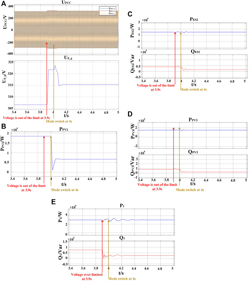
FIGURE 12. The output of the DGs in the prosumer during mode switch: (A) The voltage in PCC during mode switch; (B) The output active power of PV2 during mode switch; (C) The output active power and reactive power of ES2 during mode switch; (D) The output active power and reactive power of PV3 during mode switch; (E) The output active power and reactive power of the integrated inverter during mode switch.
6 Conclusion
This paper establishes an AC/DC hybrid prosumer with multi-type facilities and proposes the coordinated operation control strategies in different modes. The prosumer can operate in both the normal grid-connected mode and grid-fluctuation mode and the operation modes of the distributed generations will be changed accordingly. In the normal grid-connected mode, the prosumer stably connects to the power grid and provides active support. In the grid-fluctuation mode, most generations in the prosumer can participate in the frequency modulation and peak regulation with respective control strategies. Moreover, the mode-switching control strategy is proposed to make the prosumer switch from normal grid-connected mode to grid-fluctuation mode without undesired disturbance after undesired excessive grid fluctuation. With the proposed method, the prosumer can operate in different situations to support the integration of high-penetration renewables. The correctness of the proposed coordinated operation strategies is verified by the simulation results. The coordinated operation control strategies in different modes in this paper is proposed to provide suggestions for the grid connection of the prosumer with high renewables and multi-type energy sources. Under the proposed control strategies, the prosumer can provide active support for the power grid and the renewable energy utilization can be effectively improved (Wang et al., 2021).
Data availability statement
The raw data supporting the conclusion of this article will be made available by the authors, without undue reservation.
Author contributions
XH contributed to the conception of the study and performed the data analyses and wrote the manuscript. LM performed the simulation validation. CS contributed significantly to analysis and manuscript preparation.
Funding
This paper is supported by State Grid Hebei Electric Power Cooperation (under Grant: kj 2021-004).
Conflict of interest
The authors declare that the research was conducted in the absence of any commercial or financial relationships that could be construed as a potential conflict of interest.
Publisher’s note
All claims expressed in this article are solely those of the authors and do not necessarily represent those of their affiliated organizations, or those of the publisher, the editors and the reviewers. Any product that may be evaluated in this article, or claim that may be made by its manufacturer, is not guaranteed or endorsed by the publisher.
References
Boicea, V. A. (2014). Energy storage technologies: The past and the present. Proc. IEEE 102 (11), 1777–1794. doi:10.1109/JPROC.2014.2359545
Bollen, M. H. J., and Sannino, A. (2005). Voltage control with inverter-based distributed generation. IEEE Trans. Power Deliv. 20 (1), 519–520. doi:10.1109/TPWRD.2004.834679
Buraimoh, E., and Davidson, I. E. (2021). Fault ride-through analysis of current- and voltage-source models of grid supporting inverter-based microgrid. IEEE Can. J. Electr. Comput. Eng. 44 (2), 189–198. doi:10.1109/ICJECE.2020.3035036
Cady, S. T., Domínguez-García, A. D., and Hadjicostis, C. N. (2015). A distributed generation control architecture for islanded AC microgrids. IEEE Trans. Control Syst. Technol. 23 (5), 1717–1735. doi:10.1109/TCST.2014.2381601
Capuder, T., Kostelac, M., Krpan, M., and Pavić, I. (2020). “Multi-energy microgrid ability to provide flexibility services to the system operator and security of supply to end-users,” in Proceedings of the 2020 International Conference on Smart Energy Systems and Technologies (SEST),Istanbul, Turkey.September 2020 1–6. doi:10.1109/SEST48500.2020.9203390
D'Arco, S., and Suul, J. A. (2014). Equivalence of virtual synchronous machines and frequency-droops for converter-based MicroGrids. IEEE Trans. Smart Grid 5 (1), 394–395. doi:10.1109/TSG.2013.2288000
Elavarasan, R. M., Shafiullah, G. M., Sanjeevikumar, P., Manoj, N., Annapurna, A., Manavalanagar, V. A., et al. (2020). A comprehensive review on renewable energy development, challenges, and policies of leading Indian states with an international perspective. IEEE Access 8, 74432–74457. doi:10.1109/ACCESS.2020.2988011
Fan, R., Li, H., Ding, Y., Chang, X., Zhang, M., and Ji, L. (2021). “An improved control method for current-controlled VSG during transient voltage disturbance,” in Proceedings of the 2021 IEEE Sustainable Power and Energy Conference (iSPEC),Nanjing, China December 2021 112–118. doi:10.1109/iSPEC53008.2021.9735503
Hamidon, F. Z., Aziz, P. D. A., and Yunus, N. H. M. (2012). “Photovoltaic array modelling with P&O MPPT algorithm in MATLAB,” in Proceedings of the 2012 International Conference on Statistics in Science, Business and Engineering (ICSSBE), Langkawi, Malaysia, September 2012, 1–5. doi:10.1109/ICSSBE.2012.6396616
Hayder, W., Abid, A., Hamed, M. B., and Sbita, L. (2020). “Intelligenit MPPT algorithm for PV system based on fuzzy logic,” in Proceedings of the 2020 17th International Multi-Conference on Systems, Signals & Devices (SSD), Monastir, Tunisia, June 2020, 239–243. doi:10.1109/SSD49366.2020.9364195
He, J., Li, Y. W., Wang, R., and Zhang, C. (2015). Analysis and mitigation of resonance propagation in grid-connected and islanding microgrids. IEEE Trans. Energy Convers. 30 (1), 70–81. doi:10.1109/TEC.2014.2332497
Hou, G., Xing, F., Yang, Y., and Zhang, J. (2015). “Virtual negative impedance droop method for parallel inverters in microgrids,” in Proceedings of the 2015 IEEE 10th Conference on Industrial Electronics and Applications (ICIEA), June 2015, Auckland, New Zealand, 1009–1013. doi:10.1109/ICIEA.2015.7334255
Jia, Y., and Wu, R. (2016). “Voltage source grid-connected PV inverters based on MPPT and droop control,” in Proceedings of the 2016 IEEE 2nd Annual Southern Power Electronics Conference (SPEC),December 2016, Auckland, New Zealand. 1–6. doi:10.1109/SPEC.2016.7846033
Li, C., Cvetkovic, I., Burgos, R., and Boroyevich, D. (2018). “Assessment of virtual synchronous machine based control in grid-tied power converters,” in Proceedings of the 2018 International Power Electronics Conference (IPEC-Niigata 2018 -ECCE Asia),September 2012, Tsubame, Japan. 790–794. doi:10.23919/IPEC.2018.8507914
Li, F., Huang, Y., Wu, F., Liu, Y., and Zhang, X. (2018). Research on clustering equivalent modeling of large-scale photovoltaic power plants. Chin. J. Electr. Eng. 4 (4), 80–85. doi:10.23919/CJEE.2018.8606793
Liu, H., Zhang, Y., and Mantooth, H. A. (2015). “Residential renewable energy distribution system with PQ control,” in Proceedings of the 2015 IEEE International Conference on Building Efficiency and Sustainable Technologies,Shenzhen, China, December 2015, 33–38. doi:10.1109/ICBEST.2015.7435861
Liu, X., Grassi, F., Spadacini, G., and Pignari, S. A. (2020). Physically based modeling of hand-assembled wire bundles for accurate EMC prediction. IEEE Trans. Electromagn. Compat. 62 (3), 914–922. doi:10.1109/TEMC.2019.2922455
Liu, X., Wu, B., and Xiu, L. (2022). A fast positive-sequence component extraction method with multiple disturbances in unbalanced conditions. IEEE Trans. Power Electron. 37 (8), 8820–8824. doi:10.1109/TPEL.2022.3161734
Liu, X., Xiong, L., Wu, B., Qian, Y., and Liu, Y. (2022). Phase locked-loop with decaying DC transient removal for three-phase grids. Int. J. Electr. Power & Energy Syst 143, 108508. doi:10.1016/j.ijepes.2022.108508
Meng, X., Liu, J., and Liu, Z. (2019). A generalized droop control for grid-supporting inverter based on comparison between traditional droop control and virtual synchronous generator control. IEEE Trans. Power Electron. 34 (6), 5416–5438. doi:10.1109/TPEL.2018.2868722
Mortezaei, A., Simões, M. G., Durra, A. A., Marafão, F. P., and Curi Busarello, T. D. (2015). “Coordinated operation in a multi-inverter based microgrid for both grid-connected and islanded modes using conservative power theory,” in Proceedings of the 2015 IEEE Energy Conversion Congress and Exposition (ECCE),Montreal, Canada, September 2015 4602–4609. doi:10.1109/ECCE.2015.7310311
Ortega, Á., and Milano, F. (2016). Generalized model of VSC-based energy storage systems for transient stability analysis. IEEE Trans. Power Syst. 31 (5), 3369–3380. doi:10.1109/TPWRS.2015.2496217
Qiu, D., Chen, T., Strbac, G., and Bu, S. (2022). Coordination for multi-energy microgrids using multi-agent reinforcement learning. IEEE Trans. Ind. Inf., in press. doi:10.1109/TII.2022.3168319
Rizwin, M. Y., Kumar, H. R., Mayadevi, N., and Mini, V. P. (2020). “Inter-harmonics mitigation in grid-connected solar PV systems with P&O MPPT algorithm,” in Proceedings of the 2020 IEEE International Conference on Power Electronics, Drives and Energy Systems (PEDES),December 2020, Jaipur, India. 1–6. doi:10.1109/PEDES49360.2020.9379819
Ropp, M., SchultzNeely, D. J., and Gonzalez, S. (2016). “Effect of grid support functions and VRT/FRT capability on autonomous anti-islanding schemes in photovoltaic converters,” in Proceedings of the 2016 IEEE 43rd Photovoltaic Specialists Conference (PVSC),Portland, OR, USA., June 2016 1853–1856. doi:10.1109/PVSC.2016.7749942
Shen, C., Shuai, Z., Shen, Y., Peng, Y., Liu, X., Li, Z., et al. (2021). Transient stability and current injection design of paralleled current-controlled VSCs and virtual synchronous generators. IEEE Trans. Smart Grid 1 (2), 1118–1134. doi:10.1109/TSG.2020.3032610
Teng, Y., Sun, P., Hui, Q., Li, Y., and Chen, Z. (2019). A model of electro-thermal hybrid energy storage system for autonomous control capability enhancement of multi-energy microgrid. CSEE J. Power Energy Syst. 5 (4), 489–497. doi:10.17775/CSEEJPES.2019.00220
Tian, L., Cheng, L., Guo, J., and Wu, K. (2020). System modeling and optimal dispatching of multi-energy microgrid with energy storage. J. Mod. Power Syst. Clean Energy 8 (5), 809–819. doi:10.35833/MPCE.2020.000118
Wang, Z., Yi, H., Zhuo, F., Lv, N., Fan, H., Wang, F., et al. (2022). Active power control of voltage-controlled photovoltaic inverter in supporting islanded microgrid without other energy sources. IEEE J. Emerg. Sel. Top. Power Electron. 10 (1), 424–435. doi:10.1109/JESTPE.2021.3069700
Wang, Z., Yi, H., Zhuo, F., Wu, J., and Zhu, C. (2021). Analysis of parameter influence on transient active power circulation among different generation units in microgrid. IEEE Trans. Ind. Electron. 68 (1), 248–257. doi:10.1109/TIE.2019.2962447
Wang, Z., Zhuo, F., Yi, H., Wu, J., Wang, F., and Zeng, Z. (2019). Analysis of dynamic frequency performance among voltage-controlled inverters considering virtual inertia interaction in microgrid. IEEE Trans. Ind. Appl. 55 (4), 4135–4144. doi:10.1109/TIA.2019.2910784
Xie, L., Weng, G., and Zhang, Y. (2014). “Multi-level PV inverter with photovoltaic groups independent MPPT control,” in Proceedings of the 2014 17th International Conference on Electrical Machines and Systems (ICEMS),Hangzhou, China, October 2014 829–834. doi:10.1109/ICEMS.2014.7013599
Xu, R., Zhang, C., Xu, Y., Dong, Z., and Zhang, R. (2022). Multi-objective hierarchically-coordinated volt/var control for active distribution networks with droop-controlled PV inverters. IEEE Trans. Smart Grid 13 (2), 998–1011. doi:10.1109/TSG.2021.3126761
Yin, M., Xu, Y., Shen, C., Liu, J., Dong, Z. Y., and Zou, Y. (2017). Turbine stability-constrained available wind power of variable speed wind turbines for active power control. IEEE Trans. Power Syst. 32 (3), 2487–2488. doi:10.1109/TPWRS.2016.2605012
Yuan, C., Liu, C., Zhao, T., Xiao, X., and Tang, N. (2016). “Energy storage configuration strategy for virtual synchronous machine,” in Proceedings of the 2016 IEEE Energy Conversion Congress and Exposition (ECCE),Milwaukee, WI, USA, September 2016 1–6. doi:10.1109/ECCE.2016.7855080
Zhang, C., Xu, Y., Li, Z., and Dong, Z. Y. (2019). Robustly coordinated operation of a multi-energy microgrid with flexible electric and thermal loads. IEEE Trans. Smart Grid 10 (3), 2765–2775. doi:10.1109/TSG.2018.2810247
Zhou, S., Gu, Y., Song, W., Wang, C., Bai, F., and Cai, Y. (2019). “Research on control strategy of grid-connected inverter in microgrid system,” in Proceedings of the 2019 IEEE 3rd Conference on Energy Internet and Energy System Integration (EI2),Changsha, China, November 2019 392–396. doi:10.1109/EI247390.2019.9062048
Keywords: prosumer, renewable energy, distributed generation, virtual synchronous generator, coordinated operation strategy, mode-switching control
Citation: Hu X, Meng L and Su C (2023) The coordinated operation strategy of multi-type power generations in different modes in prosumer with high renewables. Front. Energy Res. 10:1091574. doi: 10.3389/fenrg.2022.1091574
Received: 07 November 2022; Accepted: 22 November 2022;
Published: 19 January 2023.
Edited by:
Liansong Xiong, Xi’an Jiaotong University, ChinaReviewed by:
Ning Li, Xi’an University of Technology, ChinaXiaokang Liu, Politecnico di Milano, Italy
Copyright © 2023 Hu, Meng and Su. This is an open-access article distributed under the terms of the Creative Commons Attribution License (CC BY). The use, distribution or reproduction in other forums is permitted, provided the original author(s) and the copyright owner(s) are credited and that the original publication in this journal is cited, in accordance with accepted academic practice. No use, distribution or reproduction is permitted which does not comply with these terms.
*Correspondence: Xuekai Hu, NzE5ODcyMzYxQHFxLmNvbQ==