 Zhen Liu1,2
 Dongsheng Xie
95% of researchers rate our articles as excellent or good
Learn more about the work of our research integrity team to safeguard the quality of each article we publish.
Find out more
ORIGINAL RESEARCH article
Front. Energy Res. , 10 January 2023
Sec. Process and Energy Systems Engineering
Volume 10 - 2022 | https://doi.org/10.3389/fenrg.2022.1088719
This article is part of the Research Topic Design, Simulation and Optimization of Hydraulic Machinery, Volume II View all 9 articles
In order to cope with the energy crisis and improve energy efficiency, the use of organic Rankine cycle (ORC) to convert low-quality heat energy into electricity and use it is an effective method. Based on the ORC waste heat recovery system of vehicle engine, this paper explores the flow heat transfer and deformation law of the core component scroll expander under different tooth head corrections. Deformation has a significant impact on the performance of the expander. In this study, several flow-thermal-solid coupling models based on double circular arc correction and double circular arc plus straight-line correction are established. The effects of tooth head correction on the strength and stiffness of tooth head, flow field distribution of suction chamber and deformation characteristics of tooth head are studied. Finally, the deformation law of scroll tooth head with different correction angles was discussed. The results show that the EA-SAL correction makes the wall curvature of the tooth head change greatly, and the flow field in the center of the tooth head becomes more uneven and complicated. The tooth head area under EA-SAL modification is larger, and the tooth head strength and stiffness are improved by about 6%. Within a certain angle range, the tooth head deformation after EA-SAL correction is slightly larger than that after PMP correction, but the difference between them decreases and even reverses with the increase of angle. The maximum deformation of the EA-SAL modified tooth head under internal pressure is about 20% smaller than that of PMP. With a given initial correction angle
In the process of industrial production, a considerable number of medium and low temperature heat sources are lost in the environment without effective utilization, such as internal combustion engine waste heat and industrial waste heat, resulting in serious energy waste (Firth et al., 2019; Lin et al., 2022). According to statistics, only about 30% of the energy generated by the typical internal combustion engine is converted into effective mechanical power, and about 60%–70% of the energy is wasted from the exhaust system and cooling system of the internal combustion engine (Lu et al., 2017a; Wang et al., 2020). Therefore, the technological recovery of engine exhaust thermal energy is crucial for improving energy efficiency, reducing emissions, and conserving energy.
In recent years, organic Rankine cycle technology has received extensive attention in the field of medium-low temperature heat source recovery technology, which is regarded as one of the most promising technologies for converting heat energy into mechanical or electrical energy (Li et al., 2017; Zhang et al., 2018; Gomaa et al., 2020; Zheng and Cao, 2020; Varshil and Deshmukh, 2021). For engine waste heat recovery, scholars have carried out research from the design of organic Rankine cycle system (Lu et al., 2017b), the improvement of waste heat recovery efficiency (Lu et al., 2017c), integrated waste heat recovery (Yu et al., 2019) and the selection of different recovery fluids (Lu et al., 2017d).
Then, the expander is an extremely important core work component in the ORC waste heat recovery system. Its working efficiency and reliability greatly affect the efficiency and technical economy of the waste heat recovery system. At present, the common volume expanders include screw type, vortex type, piston type and rotary vane type (Imran et al., 2016). Among them, scroll expander is widely used in small organic Rankine cycle waste heat recovery system because of its high efficiency, low noise, high reliability and high expansion ratio (Song et al., 2015a; Dumont et al., 2018). In the ORC waste heat recovery system of vehicle engines, the operating environment of scroll expander is relatively harsh, and its suction temperature is usually as high as 200–300°C (Zhao et al., 2017). Scrolls are often subjected to structural deformation and tooth head damage due to high temperature and internal pressure. Deformation will affect the meshing effect of the scroll teeth, causing leakage of working fluid, and serious deformation will also lead to tooth head to break. Therefore, the deformation of the scroll has a direct impact on the working performance and normal operation of the scroll expander.
At present, the research of scroll expander mainly focuses on numerical simulation of internal flow field and performance improvement. Suman et al. (2017) obtained a 5 KW oil-free scroll expander through RE procedure and CAD reconstruction, and studied the axial and radial flow characteristics and volumetric efficiency of the expander. (Emhardt et al., 2019; Emhardt et al., 2020; Emhardt et al., 2022) established a CFD model of variable wall thickness scroll expander, and studied the unsteady three-dimensional flow field, aerodynamic performance and pressure-volume ratio of the expander. The results show that the variable wall thickness design produces lower average radial and axial gas forces, and the large-scale vortex is easier to dissipate. Song et al. (2018) proposed a new bilateral symmetrical discharge structure of scroll expander, and studied the discharge flow characteristics and performance of the expander under this structure. The results show that the symmetrical discharge structure helps to reduce the pressure in the cavity and weaken the pressure distortion and secondary flow phenomenon. Xi et al. (2019) studied and analyzed the influence of expanders with different suction volumes on system performance, and found that the difference in mass flow caused by different suction volumes of expanders is the most important factor affecting system performance. Wei et al. (2015) studied the unsteady flow characteristics of the suction port and suction chamber of the expander, and revealed the flow mechanism of the vortex in the suction chamber and the expansion chamber. In addition, (Song et al., 2015b) also focused on the blocking effect at the top of the scroll tooth, and based on the CFD method, three-dimensional numerical simulations were performed on scroll expanders with suction ports at different positions. The unstable leakage flow caused by the axial and radial clearances of the expander is also studied in Ref. Song et al. (2017), Fanti et al. (2020). Most of the above simulation results explore the flow characteristics, leakage characteristics and unsteady flow field distribution of the expander. Although it provides useful guidance for the performance improvement of the scroll expander to a certain extent, it is still not enough for the structural optimization and stiffness improvement of the expander, and the deformation of the scroll plate under the action of the complex flow field of the expander is lacking. Furthermore, in the study of the deformation of scroll machinery, the research objects are mostly scroll compressors, while scroll expanders are rare. Qiang and Tao (2013) proposed a new iterative method to obtain a better temperature load distribution of the scroll, and carried out the numerical simulation of the temperature distribution of the orbiting scroll. Zheng et al. (2014) used ABAQUS software to discuss the stress distribution and deformation of the scroll at different spindle positions, and obtained the stress and deformation distribution law of the scroll. Liu et al. (2018) established multiple fluid-thermal-solid coupling models, obtained a more suitable scroll deformation distribution, and determined the time when the maximum deformation of the scroll occurred. Ullah et al. (2021) studied the deformation and the distribution of von-mises stress on the fixed and orbiting scroll of the oil-free scroll compressor. Wang et al. (2021) analyzed the variation of the gap size and potential contact between different orbiting radius scroll wraps under the influence of deformation. Although the above deformation research of scroll compressor can also provide some references for the study of expander, because the scroll expander is a reverse working process, the different internal pressure and temperature distribution will inevitably lead to different deformation behaviors. Therefore, it is necessary to conduct more in-depth deformation research on the expander.
Moreover, the tooth head of the scroll is often the most severely deformed area, so structural improvement and profile optimization of the tooth head is essential. Therefore, the correction method of the tooth head by double arc correction is introduced and the performance of the modified tooth head is studied in Ref. Lee and Wu (1995), Ma et al. (2017), Mojiri et al. (2019), Mojiri et al. (2020). Meanwhile, Ref. Liu et al. (2010), Shaffer and Groll (2013). studied the geometric model of variable wall thickness scroll tooth profile and corrected the tooth head with arc and straight line. Ref. Bell et al. (2014). gave the analytical solutions of arc-line-arc, perfect-meshing profile, one-arc and two-arc discharge geometry. In recent years, (Liu and Wu, 2015) redesigned the geometric shape of the scroll profile based on the involute generating line composed of involute and arc. Subsequently, the geometric and dynamic models of the scroll compressor are established. Wang et al. (2018) proposed a new design method for the complete meshing profiles (CMPs) of the scroll compressor, and designed three kinds of CMPs: Arc improved, arc plus line improved and asymmetric arc improved. The influence of the geometric parameters of the improved wrap on performance of the scroll compressor was analyzed. Wang et al. (2022) introduced a novel circular involute modified wrap (IMW) and gave the design method of IMW. The results show that the tooth head of IMW is thicker and the strength is increased, which can resist the higher stress near the discharge port. Obviously, the studies on tooth head modification mainly focus on the geometric model design of the modification profile, parameter comparison before and after modification, and feasibility analysis.
In summary, the internal flow characteristics of the scroll expander have been widely studied, but the research on the deformation distribution of the scroll plate is not sufficient. Especially for the tooth head with serious deformation, most of them are numerical theoretical calculations and geometric design, and the deformation comparison under different modifications of the tooth head is lacking. Therefore, the effects of different tooth head modifications on the flow field and deformation characteristics of the scroll expander cannot be visualized. Based on the above findings, in this work, the method of combining CFD numerical simulation and finite element method is adopted, and the numerical simulation results of the flow field are directly used for the boundary conditions of the finite element analysis through coupling walls. The difference in the flow field distribution of the central suction chamber, the comparison of the tooth head strength and the characteristics of tooth head deformation of the scroll expander after PMP correction and EA-SAL correction are investigated. Besides, the deformation law and strength change of tooth head under different spindle corners and different tooth head correction parameters are also studied, which provides theoretical reference for strength design, reliability research and optimization improvement of scroll expander. It has certain practical significance for indirectly improving the efficiency of ORC waste heat recovery system and improving energy utilization rate.
The scroll expander studied is modified from the scroll compressor of a certain type of vehicle air conditioner, and its main geometric parameters are shown in Table 1. The scroll expander is mainly composed of orbiting scroll and fixed scroll. The two scrolls are installed with a phase difference of 180° and mesh with each other. The orbiting scroll rotates and translates around the fixed scroll. The geometric profiles of orbiting scroll and fixed scroll are the same and are generated by circular involute profiles. The involute equation of a circle can be expressed by Eq. 1. Then, combined with the initial involute angle, the inner and outer wall profile equation of the scroll expander can be obtained, as shown in Eqs 2, 3. In SolidWorks, combined with the geometric parameters of the model and the profile equation, the geometric model of the expander is established in the form of equation driven curve, as shown in Figure 1.
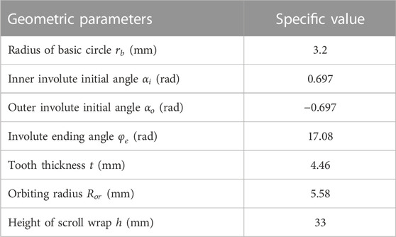
TABLE 1. Main geometric parameters.
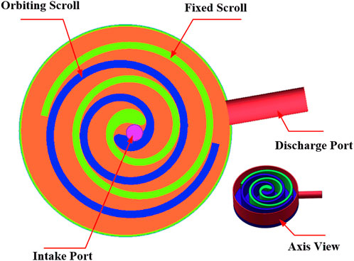
FIGURE 1. Geometric model.
Inner wall involute profile equation:
Outer wall involute profile equation:
Where
The structure design of the scroll profile is the key to the meshing of the scroll, and the processing of the profile has a greater impact on the performance and efficiency of the scroll expander. Especially for the tooth head part, if reasonable tooth head correction is not performed to avoid interference in the center part of scroll profile, the tooth head will be deformed more under high temperature and pressure, which will affect the meshing effect. In severe cases, it may even cause the tooth head to break and affect the operation of the whole machine. Nowadays, common methods of tooth head correction include dual arc correction, multiple pairs of arc correction, and arc plus straight-line correction, etc. In this paper, the influence of different tooth head corrections on the flow field distribution and deformation characteristics of the scroll is further explored by comparing the dual-arc correction and dual-arc plus straight-line correction.
The dual-arc correction is also called perfect mesh profile (PMP). The modifying curve is composed of two circular arcs, which are all tangential with the involutes at contact points, thus leading to smooth and continuous profile. For the dual-arc correction, many scholars have given the construction method (Lee and Wu, 1995; Ma et al., 2017; Mojiri et al., 2019; Mojiri et al., 2020). The correction steps can be simplified as follows: as shown in Figure 2, the coordinate system is established with the center O of the base circle of the scroll as the origin. Firstly, the modified unfold angle
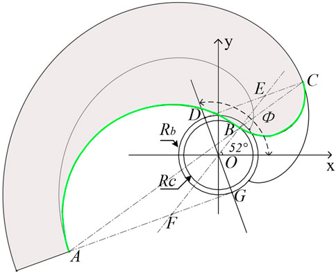
FIGURE 2. PMP correction.
The dual-arc plus straight-line correction is a correction form that combines circular arc and straight line, which is obtained on the basis of arc correction. As shown in Figure 3A, a straight line that crosses the center of the base circle and forms a γ angle with the X axis intersects the straight lines AG and CD at points F and E, respectively. Then, F and E are the centers of the two modified arcs. When the correction angle γ is variable, the degree of deviation of the center of the circle is different. Then the circle is made with AF and EC as radius respectively, and then make the common tangent of the two circles, so that the corrected straight-line MN is obtained. Finally, the redundant line segment is cut, and the dual-arc plus straight-line correction is obtained. It is found that the parameters affecting the correction of EA-SAL are mainly the modified unfold angle
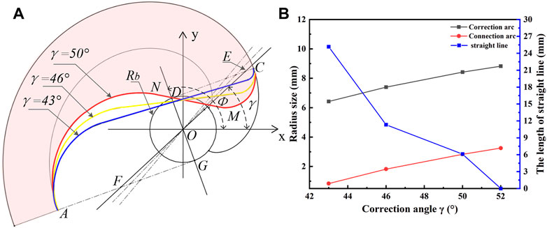
FIGURE 3. (A) EA-SAL correction (B) The relationship between the correction angle γ and the correction arc radius and the correction straight line length.
The modified scroll tooth not only avoid the tool interference, but also increase the tooth head wall thickness and improves the strength and stiffness of the tooth head. For PMP correction and EA-SAL correction, if the correction parameters are different, then the tooth head strength and the formed suction chamber volume will also be different. In this paper, the area between the modified profile and the outer involute profile indicates the thickening of the tooth head, which characterizes the strength and stiffness of the tooth head. The axial projection area of the tooth head under different correction angles and the suction volume under different rotation angles are calculated in Solid Works, which are shown in Table 2.
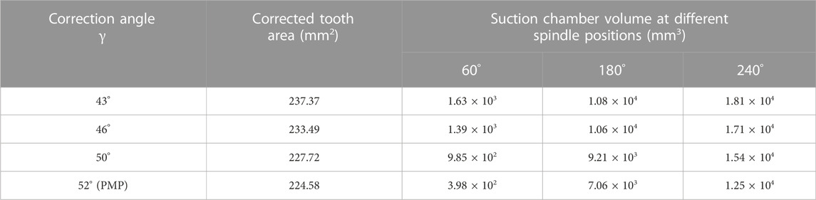
TABLE 2. Axial projection area and suction cavity volume of tooth head at different correction angles.
As can be seen from Table 2, the EA-SAL correction can increase the axial area of the tooth head, thereby increasing the overall strength of the tooth head, and the increase range is within 6%. In addition, the tooth head area decreases with the increase of correction angle γ. Therefore, appropriately reducing the correction angle γ can effectively improve the strength and stiffness of the tooth head. Meanwhile, by comparing the suction chamber volume, it can be seen that the suction chamber volume increases with the increase of the shaft rotation angles and decreases with the increase of the correction angle γ. Although the suction chamber volume under the PMP correction is small, its growth rate is greater than that under the EA-SAL correction. Figure 3B shows that the correction angle γ affects the radius of the correction arc and the length of the correction line, thus affecting the curvature change of the scroll tooth wall.
The one-way fluid-solid coupling method is adopted in this paper. Firstly, the numerical simulation of the flow field in the scroll expander is carried out in the CFD fluid software ANSYS FLUENT, and the internal temperature, pressure and velocity distribution are obtained. Then, the pressure and temperature results of CFD simulation are imported into ANSYS static model as the boundary conditions of the FEM model by coupling the wall. Finally, the stress and deformation analysis are carried out in ANSYS19.0 static model. In this paper, the flow field distribution at the center of the scroll plate and the stress and deformation at the beginning of the tooth head are specially studied.
The fluid calculation domain of scroll expander is obtained by cavity extraction in ANSYS Workbench, as shown in Figure 4A. Then, the computational domain consisting of inlet domain, outlet domain and working domain is meshed in ICEM, as shown in Figure 4B. In order to ensure the quality of the grid, the working domain grid is stretched from triangular surface grid to triangular prism grid. The inlet domain and outlet domain are meshed by hexahedral structure and they are connected to the working domain by interface. The whole calculation domain has 782,784 nodes and 1,478,268 cells.
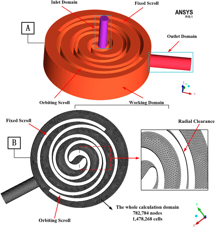
FIGURE 4. (A) Computational domains of the scroll expander (B) Illustration of the grids for computational domain.
It is meshed and then loaded into FLUENT to simulate flow and heat transfer. The whole working process obeys the continuity equation, the momentum conservation equation and the energy conservation equation. K-epsilon model is selected as the turbulence model. R123 real gas in NIST database is selected as the working fluid. Coupled algorithm is selected as the pressure-velocity coupling scheme which solves the pressure-based and momentum continuity equations together. The standard wall function method is used in the area near the wall. The inlet and outlet are set as the pressure boundary, where the total pressure and temperature are 1,000 kPa and 405 K respectively. In particular, the interfaces between gas and surfaces of scroll parts are defined as coupled walls for data transmission.
In order to verify the reliability of the numerical model, experimental measurements were carried out under four different test conditions. The test rig has been introduced in the previous work (Wei et al., 2015; Liu et al., 2018), and the test conditions are also shown in Table 3. By controlling and adjusting exhaust flow/temperature, working fluid flow/temperature, metering pump stroke, inlet/outlet gate valve opening, bypass valve opening and load, the performance parameters of expander under four working conditions are obtained. They include the flow rate, speed, effective output power, inlet/outlet pressure and temperature of the scroll expander. The output power is obtained by measuring the voltage and current of the electrical load, namely the generator electric power, as shown in Eq. 4. The mass flow rate is measured by turbine flowmeter. Meanwhile, the numerical simulation of the four working conditions is carried out, and the corresponding numerical calculation results are obtained, where the simulated shaft power can be obtained by Eq. 5. Ultimately, a comparison of the experimental results and numerical calculations results under four conditions is shown in Figures 5A, B.
Where U and I represent measured voltage and current, respectively; internal friction losses and external electro-mechanical losses are lumped into one single efficiency η; n is the rotating speed of the orbiting scroll;

TABLE 3. Operating conditions.
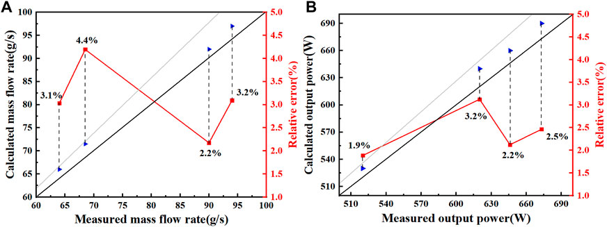
FIGURE 5. Comparisons between experimental and simulation results (A) mass flow rate and (B) output power.
It seems that the experimental results are in good agreement with the calculation results, and the maximum deviation is less than 5%. Therefore, the reliability of the calculation results is verified in a reasonable error range, and the numerical method can be used for subsequent research.
The static analysis module is established in ANSYS after importing and the scroll plate model. The global mesh size is set up and the independent mesh generation is adopted. By means of a one-way coupling method, the temperature and pressure results obtained by CFD simulation are transmitted to the finite element model as boundary conditions for the stress and deformation analysis of the scroll plate. According to the actual working conditions of the scroll expander, the corresponding displacement constraints are set for the orbiting scroll:
(1) The displacement in the Z direction of the side wall around the end plate is constrained;
(2) The displacement of the inner wall surface of the orbiting scroll bearing hole in the X and Y directions are constrained;
(3) The displacement in the Z direction of the top of the orbiting scroll bearing hole is constrained.
The scroll plate material in this study is aluminum alloy 4032, and its material parameters are shown in Table 4.
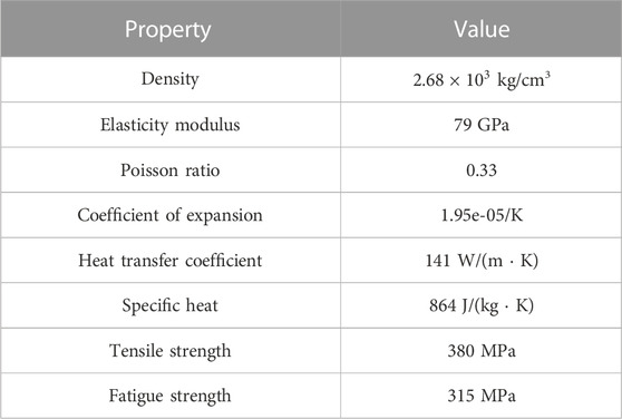
TABLE 4. Material properties.
The flow field distribution of the working chamber is affected differently by the modified profile of the tooth head with different combinations. The positions with spindle angles of 60°, 180° and 240° are selected to study the flow field distribution characteristics in the working chamber of the scroll plate after the tooth head is modified by PMP and EA-SAL.
Since the correction of the tooth head has a greater influence on the flow field distribution at the center of the tooth head, this paper mainly studies the flow field distribution of the central suction chamber of the scroll expander. In order to better observe the spatial distribution of the flow field after PMP correction and EA-SAL correction, the circular planes with z = 8 mm, 18 mm and 28 mm are established in CFD-POST with the center of the fixed scroll as the center. When the shaft rotation angle is 60°, the temperature distribution of the central suction chamber under PMP and EA-SAL correction is shown in Figure 6.
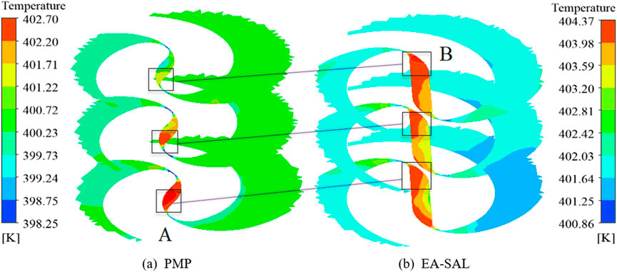
FIGURE 6. Temperature distribution in the center of tooth head at 60° angle.
It can be seen from the cloud diagram that when the shaft rotates to the position of 60°, the temperature at the center of the scroll plate under the two tooth head corrections is lower than that at other positions. This is because at this position, the connecting area between the inlet and the central suction chamber is nearly blocked by the orbiting scroll, which causes mall connected area and serious throttling. In addition, it shows that the temperature at the center of the scroll under the EA-SAL correction is greater than that under PMP correction by comparing the temperature scales. The average difference is about 2 K and the reason is that different tooth head modifications will cause different tooth head shapes. The modified geometric structure of EA-SAL makes the larger volume of the central suction chamber formed by meshing, which leads to more high temperature working fluid being inhaled. As shown in the frame line in the figure, the positions of the maximum temperature in the suction chamber under the two corrections are different. They are distributed at both ends of the suction chamber. This is caused by the position of the inlet port and the correction profile. In the case of PMP correction, the radius of the correction arc is larger than that of the connection arc, so the working fluid is more likely to flow to the A side along the fixed scroll wall. In the case of EA-SAL correction, the inlet port is located at the correction straight line position and close to side B, so the temperature of side B is higher.
With the rotation of the spindle, the connected area between the inlet port and the suction chamber increases, the throttling weakens, and the temperature of the working chamber increases. At the 180° position, the opening of the inlet port is the largest, and the temperature of the central suction chamber is the highest. However, due to different tooth head profile and different curvature changes, there are differences in the temperature distribution of the suction chamber. As shown in Figures 7A, B, the temperature is the highest in the vertical direction of the inlet port, and is slightly lower on both sides. The temperature near the surface of the orbiting scroll and the meshing point has obvious stratification and is relatively small. In addition, along the downward direction of the Z axis, the area of high temperature becomes larger and larger, and the temperature distribution is uneven. As shown in Figure 7C, the high temperature working fluid enters the central suction chamber and flows rapidly along the direction of the tooth height. When the airflow hits the end plate of the orbiting scroll, the velocity decrease and the direction changes, so that a local high temperature is obtained in the lower part of the suction chamber. In comparison, it can be found that this phenomenon is weaker under EA-SAL correction. The reason is that the combination of arc and straight line makes the flow fluctuation smaller. It is more favorable for the working fluid to the flow and transfer heat and easier to disperse to the surrounding during the flow process.
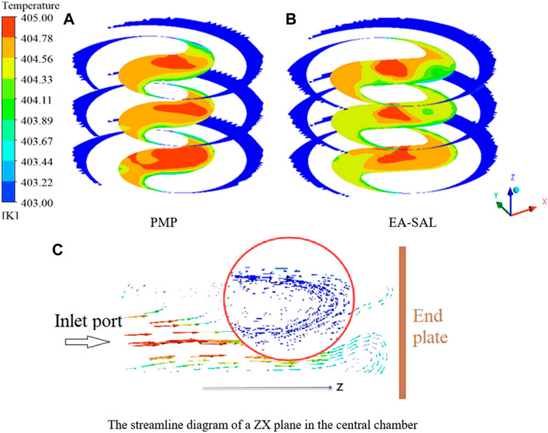
FIGURE 7. (A,B) are the temperature distribution of the central suction chamber of the tooth head after PMP correction and EA-SAL correction at 180° angle, respectively; (C) is the streamline diagram of ZX plane of central chamber.
As shown in Figure 8, at the 240° spindle rotation angle, the temperature distribution of the central suction chamber of the two modified scroll plates shows polarization. Which means taking the suction center as the boundary, the temperature distribution on both sides is quite different. The temperature on the left is higher than that on the right. In addition, the temperature on the right side is unevenly distributed with local high temperature. The specific reason is that the working fluid flows more smoothly towards the left side along the inner wall of the fixed scroll under the action of kinetic energy after entering the central suction chamber. On the contrary, the working fluid flowing to the right side is blocked by a part of the inner wall of the orbiting scroll. Therefore, the working fluid gas on the left side accumulates quickly, resulting in temperature rise and more uniform distribution. On the right side, the average temperature under the PMP correction is greater than that under EA-SAL correction. The reason is that the curvature of the connecting arc at the beginning of the tooth head of the former is smaller than that of the latter, so it is more conducive to the flow of working fluid. As shown by the circle in the figure, local high temperature appears under both corrections, and this phenomenon is more obvious under EA-SAL correction. The reason for this phenomenon is that the flow of working fluid at the circle is significantly blocked by the wall, and the curvature is large. This leads to the decrease of working fluid flow velocity, the formation of local low-speed vortex and the increase of temperature.
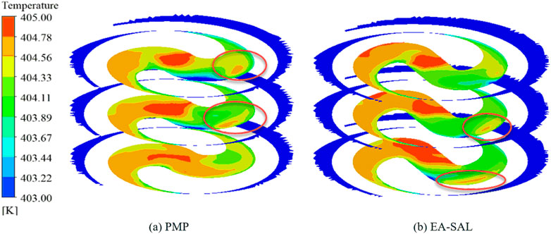
FIGURE 8. Temperature distribution in the center of tooth head at 240° angle.
At different spindle rotation angles, the pressure distribution of the central suction chamber of the scroll after PMP correction and EA-SAI correction is shown in Figures 9A–C and Figures 9D–F. When the spindle angle is 60°, the pressure value at the center of the scroll under EA-SAL correction is significantly greater than that under PMP correction. The reason is the same as the temperature distribution. In this position, the former suction chamber volume is larger and more high-pressure gas is inhaled. With the rotation of the orbiting scroll, the volume changing rate of the suction chamber in the center of the scroll under the PMP correction is greater, so the gap between the two corrections is gradually reduced. At the angle of 180°, the average pressure under the PMP correction is greater than that under EA-SAL correction. At the angle of 240°, the pressure value under EA-SAL correction is higher than that under PMP correction by about 5 kPa. In addition, due to the combination of circular arc and straight line at this position, the pressure distribution is uneven caused by the more complex flow of the working fluid in the central suction chamber and the larger flow resistance is larger.
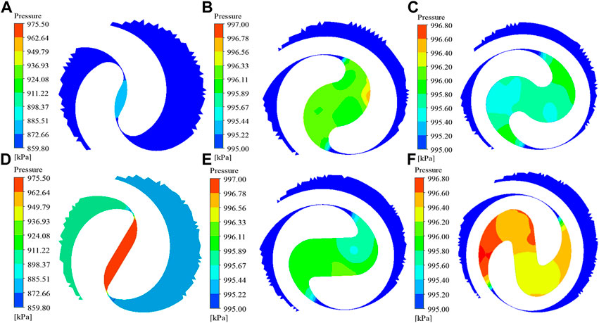
FIGURE 9. (A–C) and (D–F) are the pressure distribution of the spindle angle at 60°, 180° and 240° under PMP correction and EA-SAL correction, respectively.
The numerical simulation results of flow field calculated by CFD are imported into the static analysis module for stress and deformation analysis of scroll tooth. In order to observe the deformation law of the scroll tooth under the two tooth head correction methods more directly, the deformation curve of the top of the scroll tooth is drawn. The deformation curve is drawn by taking the modified starting point of the scroll tooth head as the origin, the inner arc length as x coordinate and the deformation amount as y coordinate. In this paper, the arc length range of 1–50 mm is selected to make a comparative analysis of tooth head deformation after PMP correction and EA-SAL correction.
In Figures 10A–F show the top deformation curves of the orbiting scroll tooth head modified by PMP and EA-SAL under the action of temperature load at 60°, 180° and 240° angles position respectively. It can be seen intuitively from the curve distribution that the temperature load has a greater influence on the axial deformation of the tooth head. The axial deformation trend of the tooth head under the two corrections are basically the same, which gradually decrease outward along the scroll profile. The axial deformation of the tooth head under EA-SAL correction is slightly larger than that under PMP correction within a certain range of spindle rotation angle. However, the gap between them is reduced with the increase of spindle rotation angle and is eventually reversed. At the position of 60° angle, the average difference of axial deformation is 8um. The reason is the same as the flow field analysis. At this position, the average temperature at the center of the tooth head under EA-SAL correction is higher than that under PMP correction, so the thermal stress deformation is slightly larger than that under PMP correction. Since the modified tooth is thicker and the degrees of freedom in the X and Y directions of the bearing holes are limited, the figure shows that the radial deformation is smaller than the axial deformation. In addition, the former part of the radial deformation curve shows a downward trend, because this stage is in the connecting arc section. The curvature of the position is larger, the flow rate of the working fluid is faster, and the internal energy conversion is high, which makes the deformation in a contraction state. The large fluctuation of radial deformation at the 60° position is caused by the large change of temperature gradient and the change of direction. Moreover, the average difference of radial deformation between the tooth heads is less than 5 um, and all of them tend to increase outward.
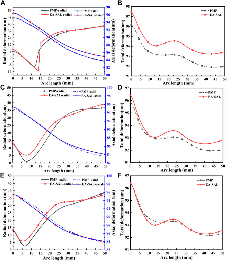
FIGURE 10. The top deformation curve under temperature load at different spindle positions [(A,B)-60°; (C,D)-180°; (E,F)-240°].
It is not difficult to find that the overall total deformation of the tooth head corrected by EA-SAL is slightly larger than that by PMP based on the total deformation curve under temperature load. Moreover, their difference gradually decreases with the increase of the angle, which is related to the temperature distribution at different rotation angles. In the range of 0–12 mm arc length, the tooth thickness gradually increases from the beginning of the tooth head, so the larger wall thickness reduces the bending stress caused by the temperature, resulting in rapid reduction of deformation.
The top deformation curves of tooth head modified by PMP and EA-SAL under internal pressure load at different spindle positions are shown in Figures 11A–F. From the deformation curves at different spindle positions, it can be seen that the trends of radial deformation distribution of the tooth head modified by the two methods are roughly the same. However, due to the different correction forms and different tooth thickness, the deformation is different in the local range. In general, the average deformation of the tooth after PMP correction is greater than that after EA-SAL correction. At the angle of 60°, the deformation curves under the two modifications both show steep inflection points. The EA-SAL shows expansion effect, whilst the PMP shows contraction effect. This can be attributed to the deformation fluctuation near the inlet port caused by the sudden large pressure difference between the inside and outside of scroll tooth.
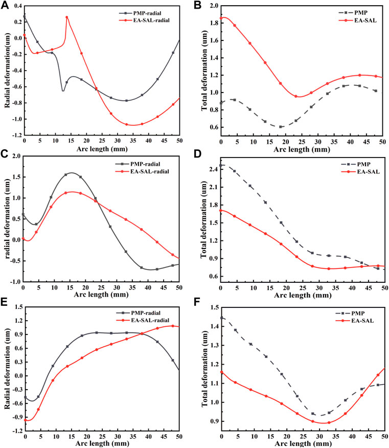
FIGURE 11. The top deformation curve under pressure load at different spindle positions [(A,B)-60°; (C,D)-180°; (E,F)-240°].
As can be observed from the total pressure deformation curve, the total pressure deformation of the tooth head after EA-SAL correction is greater than that of the tooth head after PMP correction at a small spindle angles because of the difference in suction chamber volume. However, with the increase of rotation angle, under the influence of expansion volume and tooth head wall thickness, the deformation effect of the two corrections is reversed. The total deformation of the tooth head under PMP correction is gradually larger than that under EA-SAL. Therefore, it can be seen that the deformation of the tooth head is complex and changeable, which is affected by temperature, pressure, correction method and spindle rotation angle.
In Figures 12, 13 show deformation curves of scroll tooth heads corrected by different correction angles under temperature load and pressure load at the same rotation angle. From the deformation curve under temperature load, it can be seen that the deformation trend of the tooth head after correction with different correction angles is similar, the PMP correction has a smoother trend and less fluctuation than the EA-SAL correction. Combined with the data in Table 5, it can be found that the deformation of tooth head under the action of temperature load decreases with the decrease of correction angle. The deformation difference between the EA-SAL correction of γ = 43° and the PMP correction of γ = 52° under the action of temperature load is larger. The reason is that the thickness of the tooth head corrected by EA-SAL is larger and less affected by thermal stress. So appropriately reducing the correction Angle is conducive to reducing the deformation caused by thermal stress.
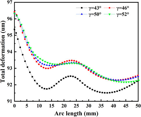
FIGURE 12. Deformation of tooth heads with different correction angles under temperature load.
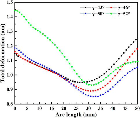
FIGURE 13. Deformation of tooth heads with different correction angles under pressure load.
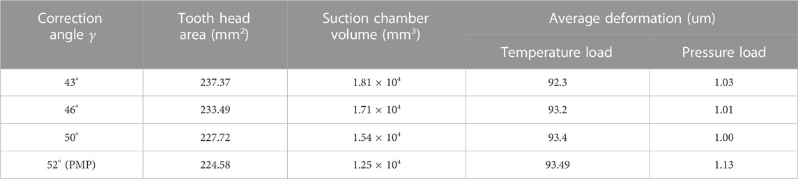
TABLE 5. The data of tooth heads with different correction angles.
From the deformation curve under internal pressure load, it can be seen that the overall deformation of the tooth head under PMP correction is greater than that under EA-SAL correction, and the difference is significant at the front end of the tooth head, which is about 20%. In addition, as the EA-SAL correction increases the tooth thickness, the deformation of the tooth head under different correction angles is relatively close. Under the action of internal pressure, the deformation of tooth head also decreases with the decrease of the correction angle. But after 30 mm, the deformation gradually increases, and the smaller the correction angle, the greater the deformation. The reason is that the smaller the correction angle, the greater the rate of change of the tooth thickness, resulting in greater changes in the amount of deformation.
In this research, CFD numerical simulation and finite element method are combined to study the influence of tooth modification on the internal flow field and tooth head deformation of a scroll expander in an ORC waste heat recovery system. Meanwhile, by changing the parameter value of the tooth head modification, the deformation law and strength change of the tooth head under different modification parameters are explored. The main conclusions are as follows:
(1) The EA-SAL corrected tooth head has a larger head area, a larger central suction chamber volume and better head strength. In addition, the tooth head area decreases with increasing correction angle γ.
(2) The EA-SAL modified profile makes the curvature of the tooth head wall change greatly, resulting in more uneven distribution of the flow field in the center chamber of the tooth head and more complicated flow.
(3) The deformation trend of the two corrected tooth heads is basically the same, both decreasing along the scroll profile towards the outer ring, while the axial deformation of the tooth head under temperature load is obvious. Within a certain range of rotation angles, the thermal deformation of the tooth head after EA-SAL correction is slightly larger than that after PMP correction. However, the gap gradually decreases or even reverses with the increase of the spindle rotation angle. Additionally, the average total deformation of the PMP corrected tooth head under internal pressure loading is greater.
(4) With a given initial correction angle
The research provides a theoretical basis for the optimization design and performance improvement of scroll expander, but it is far from enough. In the future work, on the basis of this study, the suction port structure suitable for different tooth head structures can be explored to better improve the performance of the expander.
The original contributions presented in the study are included in the article/Supplementary Material, further inquiries can be directed to the corresponding author.
The writing—original draft preparation: DX and ZhLiu; Writing—review and editing: ZhLiu; Methodology: ZhLi and ZeL; Validation: TH; Data curation: DX; Funding: ZhLiu.
The study and the related experiments were supported by Hubei Key Laboratory of Power System Design and Test for Electrical Vehicle, Hubei Natural Science Foundation Youth Project (2020CFB320) and Hubei Superior and Distinctive Discipline Group of “New Energy Vehicle and Smart Transportation” (XKTD012022).
The authors declare that the research was conducted in the absence of any commercial or financial relationships that could be construed as a potential conflict of interest.
All claims expressed in this article are solely those of the authors and do not necessarily represent those of their affiliated organizations, or those of the publisher, the editors and the reviewers. Any product that may be evaluated in this article, or claim that may be made by its manufacturer, is not guaranteed or endorsed by the publisher.
Bell, I. H., Groll, E. A., Braun, J. E., Horton, W., and Lemort, V. (2014). Comprehensive analytic solutions for the geometry of symmetric constant-wall-thickness scroll machines. Int. J. Refrig. 45, 223–242. doi:10.1016/j.ijrefrig.2014.05.029
Dumont, O., Parthoens, A., Dickes, R., and Lemort, V. (2018). Experimental investigation and optimal performance assessment of four volumetric expanders (scroll, screw, piston and roots) tested in a small-scale organic Rankine cycle system. Energy 165, 1119–1127. doi:10.1016/j.energy.2018.06.182
Emhardt, S., Song, P., Tian, G., Chew, J., and Wei, M. (2019). CFD analysis of variable wall thickness scroll expander integrated into small scale ORC systems. Energy Procedia 158, 2272–2277. doi:10.1016/j.egypro.2019.01.241
Emhardt, S., Tian, G., Song, P., Chew, J., and Wei, M. (2022). CFD analysis of the influence of variable wall thickness on the aerodynamic performance of small scale ORC scroll expanders. Energy 244, 122586. doi:10.1016/j.energy.2021.122586
Emhardt, S., Tian, G., Song, P., Chew, J., and Wei, M. (2020). CFD modelling of small scale ORC scroll expanders using variable wall thicknesses. Energy 199, 117399. doi:10.1016/j.energy.2020.117399
Fanti, G. R., Romão, D. A., de Almeida, R. B., and de Mello, P. E. (2020). Influence of flank clearance on the performance of a scroll expander prototype. Energy 193, 116823. doi:10.1016/j.energy.2019.116823
Firth, A., Zhang, B., and Yang, A. (2019). Quantification of global waste heat and its environmental effects. Appl. Energy 235, 1314–1334. doi:10.1016/j.apenergy.2018.10.102
Gomaa, M. R., Mustafa, R. J., Al-Dhaifallah, M., and Rezk, H. (2020). A low-grade heat Organic Rankine Cycle driven by hybrid solar collectors and a waste heat recovery system. Energy Rep. 6, 3425–3445. doi:10.1016/j.egyr.2020.12.011
Imran, M., Usman, M., Park, B. S., and Lee, D. (2016). Volumetric expanders for low grade heat and waste heat recovery applications. Renew. Sustain. Energy Rev. 57, 1090–1109. doi:10.1016/j.rser.2015.12.139
Lee, Y. R., and Wu, W. F. (1995). On the profile design of a scroll compressor. Int. J. Refrig. 18, 308–317. doi:10.1016/0140-7007(95)00013-2
Li, L., Ge, Y. T., Luo, X., and Tassou, S. A. (2017). Experimental investigations into power generation with low grade waste heat and R245fa Organic Rankine Cycles (ORCs). Appl. Therm. Eng. 115, 815–824. doi:10.1016/j.applthermaleng.2017.01.024
Lin, Y., Chong, C. H., Ma, L., Li, Z., and Ni, W. (2022). Quantification of waste heat potential in China: A top-down societal waste heat accounting model. Energy 261, 125194. doi:10.1016/j.energy.2022.125194
Liu, T., and Wu, Z. (2015). Modeling of top scroll profile using equidistant-curve approach for a scroll compressor. Math. Problems Eng. 112, 121–128. doi:10.1155/2015/403249
Liu, Y., Hung, C., and Chang, Y. (2010). Study on involute of circle with variable radii in a scroll compressor. Mech. Mach. Theory 45, 1520–1536. doi:10.1016/j.mechmachtheory.2010.07.001
Liu, Z., Wei, M., Song, P., Emhardt, S., Tian, G., and Huang, Z. (2018). The fluid-thermal-solid coupling analysis of a scroll expander used in an ORC waste heat recovery system. Appl. Therm. Eng. 138, 72–82. doi:10.1016/j.applthermaleng.2018.04.048
Lu, Y., Roskilly, A. P., Jiang, L., Chen, L. F., and Yu, X. (2017). Analysis of a 1 kW organic Rankine cycle using a scroll expander for engine coolant and exhaust heat recovery. Front. Energy 11, 527–534. doi:10.1007/s11708-017-0516-0
Lu, Y., Roskilly, A. P., Jiang, L., and Yu, X. (2017). Working fluid selection for a small-scale organic Rankine cycle recovering engine waste heat. Energy Procedia 123, 346–352. doi:10.1016/j.egypro.2017.07.266
Lu, Y., Roskilly, A. P., Smallbone, A., Yu, X., and Wang, Y. (2017). Design and parametric study of an Organic Rankine cycle using a scroll expander for engine waste heat recovery. Energy Procedia 105, 1420–1425. doi:10.1016/j.egypro.2017.03.530
Lu, Y., Roskilly, A. P., Tang, K., Wang, Y., Jiang, L., Yuan, Y., et al. (2017). Investigation and performance study of a dual-source chemisorption power generation cycle using scroll expander. Appl. Energy 204, 979–993. doi:10.1016/j.apenergy.2017.02.068
Ma, Z., Bao, H., and Roskilly, A. P. (2017). Dynamic modelling and experimental validation of scroll expander for small scale power generation system. Appl. Energy 186, 262–281. doi:10.1016/j.apenergy.2016.08.025
Mojiri, A., Mikel, M., and Barber, T. (2020). Compression chamber volume analysis for co-rotating scroll compressors. Int. J. Refrig. 112, 172–188. doi:10.1016/j.ijrefrig.2020.01.005
Mojiri, A., Mikel, M., and Tracie, B. (2019). Geometry of wrap profiles in Co-rotating scroll compressors. Int. J. Refrig. 106, 327–337. doi:10.1016/j.ijrefrig.2019.06.032
Qiang, J. G., and Tao, W. (2013). Numerical modelling of temperature distribution for orbiting scroll wrap in an air scroll compressor. Int. J. Heat Mass Transf. 67, 678–689. doi:10.1016/j.ijheatmasstransfer.2013.08.066
Shaffer, B. R., and Groll, E. A. (2013). Variable wall thickness scroll geometry modeling with use of a control volume approach. Int. J. Refrig. 36, 1809–1820. doi:10.1016/j.ijrefrig.2013.08.003
Song, P., Wei, M., Liu, Z., and Zhao, B. (2015). Effects of suction port arrangements on a scroll expander for a small scale ORC system based on CFD approach. Appl. Energy 150, 274–285. doi:10.1016/j.apenergy.2015.04.046
Song, P., Wei, M., Shi, L., Danish, S. Y., and Ma, C. (2015). A review of scroll expanders for organic rankine cycle systems. Appl. Therm. Eng. 75, 54–64. doi:10.1016/j.applthermaleng.2014.05.094
Song, P., Wei, M., Zhang, Y., Sun, L., Emhardt, S., and Zhuge, W. (2018). The impact of a bilateral symmetric discharge structure on the performance of a scroll expander for ORC power generation system. Energy 158, 458–470. doi:10.1016/j.energy.2018.06.053
Song, P., Zhuge, W., Zhang, Y., Zhang, L., and Duan, H. (2017). Unsteady leakage flow through axial clearance of an ORC scroll expander. Energy Procedia 129, 355–362. doi:10.1016/j.egypro.2017.09.221
Suman, A., Randi, S., Casari, N., Pinelli, M., and Nespoli, L. (2017). Experimental and numerical characterization of an oil-free scroll expander. Energy Procedia 129, 403–410. doi:10.1016/j.egypro.2017.09.120
Ullah, H., Bin, P., Bocko, J., Zhang, P., and Zhang, Y. (2021). Stress and deformation analysis of oil-free air scroll compressor. J. Phys. Conf. Ser. 1877, 012004. doi:10.1088/1742-6596/1877/1/012004
Varshil, P., and Deshmukh, D. (2021). A comprehensive review of waste heat recovery from a diesel engine using organic rankine cycle. Energy Rep. 7, 3951–3970. doi:10.1016/j.egyr.2021.06.081
Wang, C., Zhang, S., Cheng, J. M., Lei, B. W., Du, Y. J., and Wu, J. H. (2021). Simulation of the deformation and contact of scrolls in the scroll compressor. Mater Sci. Eng. 1180, 012013. doi:10.1088/1757-899x/1180/1/012013
Wang, J., Han, Y., Xi, Z., Wang, Z., and Cui, D. (2022). Geometric design and analysis of scroll compressors with a novel circular involute modified wrap. Proc. Institution Mech. Eng. Part E J. Process Mech. Eng. 236, 964–974. doi:10.1177/09544089211053075
Wang, J., Liu, Q., Cao, C., Wang, Z., Li, Q., and Qu, Y. (2018). Design methodology and geometric modeling of complete meshing profiles for scroll compressors. Int. J. Refrig. 91, 199–210. doi:10.1016/j.ijrefrig.2018.05.011
Wang, X., Shu, G., Tian, H., Wang, R., and Cai, J. W. (2020). Dynamic performance comparison of different cascade waste heat recovery systems for internal combustion engine in combined cooling, heating and power. Appl. Energy 260, 114245. doi:10.1016/j.apenergy.2019.114245
Wei, M., Song, P., Zhao, B., Shi, L., Wang, Z., and Ma, C. (2015). Unsteady flow in the suction process of a scroll expander for an ORC waste heat recovery system. Appl. Therm. Eng. 78, 460–470. doi:10.1016/j.applthermaleng.2015.01.010
Xi, H., Li, M. J., Zhang, H., and He, Y. (2019). Experimental studies of organic Rankine cycle systems using scroll expanders with different suction volumes. J. Clean. Prod. 218, 241–249. doi:10.1016/j.jclepro.2019.01.302
Yu, X., Li, Z., Lu, Y., Huang, R., and Roskilly, A. P. (2019). Investigation of organic Rankine cycle integrated with double latent thermal energy storage for engine waste heat recovery. Energy 170, 1098–1112. doi:10.1016/j.energy.2018.12.196
Zhang, H., Guan, X., Ding, Y., and Liu, C. (2018). Emergy analysis of Organic Rankine Cycle (ORC) for waste heat power generation. J. Clean. Prod. 183, 1207–1215. doi:10.1016/j.jclepro.2018.02.170
Zhao, M., Wei, M., Song, P., Liu, Z., and Tian, G. (2017). Performance evaluation of a diesel engine integrated with ORC system. Appl. Therm. Eng. 115, 221–228. doi:10.1016/j.applthermaleng.2016.12.065
Zheng, Q., Yang, B., Chen, N., Yang, H. M., and Hu, M. (2014). Numerical simulation analysis for scroll of scroll compressor based on ABAQUS. Appl. Mech. Mater. 488, 1047–1051. doi:10.4028/www.scientific.net/amm.488-489.1047
Keywords: ORC waste heat recovery, scroll expander, PMP (dual-arc correction), EA-SAL (dual-arc plus straight-line correction), flow field and deformation distribution
Citation: Liu Z, Xie D, Li Z, Huang T and Liu Z (2023) Effect of tooth head modification on the performance of a scroll expander for ORC waste heat recovery system. Front. Energy Res. 10:1088719. doi: 10.3389/fenrg.2022.1088719
Received: 03 November 2022; Accepted: 07 December 2022;
Published: 10 January 2023.
Edited by:
Ling Zhou, Jiangsu University, ChinaReviewed by:
Fubin Yang, Beijing University of Technology, ChinaCopyright © 2023 Liu, Xie, Li, Huang and Liu. This is an open-access article distributed under the terms of the Creative Commons Attribution License (CC BY). The use, distribution or reproduction in other forums is permitted, provided the original author(s) and the copyright owner(s) are credited and that the original publication in this journal is cited, in accordance with accepted academic practice. No use, distribution or reproduction is permitted which does not comply with these terms.
*Correspondence: Dongsheng Xie, MTYyMjY4ODE0NkBxcS5jb20=
Disclaimer: All claims expressed in this article are solely those of the authors and do not necessarily represent those of their affiliated organizations, or those of the publisher, the editors and the reviewers. Any product that may be evaluated in this article or claim that may be made by its manufacturer is not guaranteed or endorsed by the publisher.
Research integrity at Frontiers
Learn more about the work of our research integrity team to safeguard the quality of each article we publish.