 Qunying Liu
94% of researchers rate our articles as excellent or good
Learn more about the work of our research integrity team to safeguard the quality of each article we publish.
Find out more
ORIGINAL RESEARCH article
Front. Energy Res., 06 January 2023
Sec. Process and Energy Systems Engineering
Volume 10 - 2022 | https://doi.org/10.3389/fenrg.2022.1088563
This article is part of the Research TopicPlanning and Operation of Hybrid Renewable Energy Systems, Volume IIView all 12 articles
The absorption and output characteristics of reactive power of the doubly-fed induction generator (DFIG) greatly influence the voltage stability of PCC (Point of Common Coupling) where the wind farms are integrated into the bulk power grid. This study proposes a reactive power compensation strategy for coordinated voltage control (CVC) of PCC with large-scale wind farms to achieve the expected voltage quality of the power grid through a minimum amount of control actions in emergencies. To this end, the mechanism of reactive power and voltage control inside DFIG is first analyzed. Then, the concept of reactive power reserve (RPR) sensitivity concerning control actions is introduced and an index of voltage stability margin is proposed to evaluate and analyze the distance between the current operating point and the voltage collapse point by analyzing the relationship between reactive power reserve and voltage stability margin. In the event of an emergency, critical reactive power reserves are obtained to reduce the dimension and complexity of the control problem. The sensitivity of reactive power reserve and the control are formulated into a convex quadratic programming problem to optimize the control strategies for voltage stability. The proposed technology has been validated on the IEEE 39-bus system.
Because of the development of power electronics control techniques, high penetration of wind farm dominated by DFIG will become a prominent characteristics of power system motivated by the “double carbon” strategy recognized by the whole world. However, grid integration of multiple wind farms through long transmission lines brings about great challenges to system voltage stability due to the stochasticity and variability of wind generations, which tends to cause the tripping of wind farms, even a widespread event or potential system collapse. The RPR is a critical metric to maintain voltage stability, which is an essential information source for voltage stability boundary estimation (Dong et al., 2005). Therefore, it is important to assess the reactive power reserve of the key buses based on the local information (Sissine, 2007). Considering the voltage control cost and the control effects, to control all the voltage buses is unrealistic. Hence, to find the important buses which are sensitive to reactive power compensation is recognized to be prominent to improve voltage stability.
According to the research published in recent years, CVC has commonly included three steps: 1)Discovering the relationship of voltage stability margin and RPR to determine the buses sensitive to the reactive power (El-Araby and Yorino, 2018; Han et al., 2018); 2)Calculating the RPR in power system (Li et al., 20132013; Jankowski et al., 20172017); 3)Controlling voltage by coordinating the active power production, reactive compensation devices and transformers (Qinyu et al., 20182018; Ouyang et al., 2019), especially in the power system inter-collected with wind farm (Leonardi and Ajjarapu, 2012; Huang et al., 2020). Ref. (Ghosh et al., 2020).has proposed a dynamic CVC architecture for reactive power capability enhancement of the DFIG-based wind power generation. To improve the control effect, ref. (Zhang et al., 2020). has proposed an optimal sensitivity to online track the accurate RPR of wind farms. ref. (Ren et al., 2022).based on the tabu search algorithm, the reactive power compensation amount of each field area is calculated with the minimum nodal voltage index and the maximum margin index as the objective function.Based on the local voltage profile to identify the emergency, (Ma et al., 2022). has performed a adaptive voltage control. Based on the clustered effective reactive reserve, (Park et al., 2021). Has proposed an indicator to identify the risk of dynamic voltage stability.Based on the second-order trajectory sensitivity analysis, (Hu et al., 2021). Has proposed a robust DVR assessment method to determine both the inductive and capacitive DVR. (Oliveira and Bollen, 2022). Has proposed a dynamic CVC strategy to enhance the reactive power capability of the DFIG during grid faults.
The CVC strategy tends to formulate a MLP (Multi-objectives Linear Programming) problems (Grudinin, 1998; Gabash and Li, 2012), the control effect depends on whether the optimal solution of MLP is found. Due to the complexity, insecure convergence, and high computational cost, how to calculate the optimal solutions, and also improve the convergence at the same time is still a hot topic (Sun et al., 2017).
The optimal solutions tend to include the reactive power compensation location, the reactive power compensation amount and the voltage improvement, and so on. In (De and Goswami, 2014), Artificial Bee Colony algorithm has been used to solve optimum power flow (OPF) problems, which is formed by three new RPP methods. In (Ding et al., 2016), the conic relaxation based branch flow formulation has been employed to set up a mixed integer convex programming model, and the second order cone programming based column-and-constraint generation algorithm is utilized to solve the proposed two-stage robust reactive power optimization model. In (Mugemanyi et al., 2020), the chaotic bat algorithm is applied to solve the optimal reactive power dispatch problem taking into account small-scale, medium-scale and large-scale power systems. In (Ibrahim et al., 2022), a voltage secure multi-period optimal reactive power dispatch problem has been formulated and OPTALG and GridOpt have been used to solve the optimization problem.
According to the aforementioned research, few studies have explored the relationship between control action and RPR. Hence the precise control is difficult to perform. However, the search for the optimal solution in reactive power optimization is still time-consuming, which makes it difficult to apply the above methods online. For these reasons, our research work is focused on two aspects:
1) To determine the key buses and weak areas of the system for voltage stability, the calculation method of R sensitivity with respect to control actions is proposed. Based on RPR sensitivity, the point-to-point voltage support capability is analyzed to determine the priority and weighting factor of different control variables (e.g., active power of DFIG, equivalent susceptance of shunt capacitor, and load shedding);
2) The convex quadratic programming problem with voltage stability as the objective is established. A convex quadratic programming problem is formulated with inequality constraint in this research to obtain an optimal control amount. Furthermore, the modified genetic algorithm (MGA) approach is proposed to solve it with less computation complexity while achieving better convergence.
This paper is organized as follows: Section 2 introduces the concept of voltage reactive power sensitivities with respect to control actions and Section 3 describes how the index of voltage stability margin is established. The control strategy of reactive power compensation is explained in Section 4. How to determine the optimal control amount is discussed in Section 5. Section 6 shows the results of the proposed approach applied to the IEEE 39-bus system. Finally, the conclusion and future work are addressed in Section 1.
To define the concept of reactive power reserve of the doubly-fed induction generator, the reactive regulation characteristic of DFIG is analyzed. The definition of traditional reactive power control inside DFIG is introduced in (Mugemanyi et al., 2020). The typical configuration of the DFIG system is shown in Figure 1.
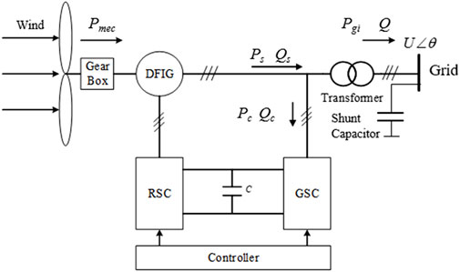
FIGURE 1. Configuration of doubly-fed induction generator.
In Figure 1, the rotor-side converter (RSC) is used to control the maximum of the active power production, and the grid-side converter (GSC) is used to control the reactive power before participating in the voltage support.
The output of reactive power of the DFIG is Q, which is composed of the reactive power Qs on the stator side and the reactive power
In Eq. 2,
In Eq. 3,
The reactive power reserve refers to the reserved adjustable margin for the DFIG, which can adjust the terminal voltage fast. In some emergencies, such as asymmetrical short-circuit faults, the reactive power reserve can be used to support the deteriorating voltage stability. The capacity of reactive power reserve RPR of the doubly-fed induction generator can be expressed as
During the operation process, the reactive power reserve of DFIG is determined both by itself and the demand from the grid side. On the DFIG side, it can be obtained from the PV and PQ curves. Because the total capacity is a given value, the change in the active power of the DFIG tends to cause the decreased reactive power reserve, which as a result will influence the voltage stability. The PQ curve of the stator side of the DFIG is shown by the dotted line in Figure 2, which is a semi-circle with
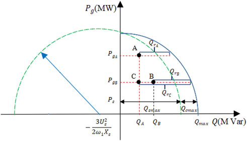
FIGURE 2. PQ Curve of doubly-fed Wind Turbine.
By considering the output of the grid-side converter, the PQ curve of the DFIG is shown by the solid line. On the grid side, two potential control actions have been considered: the shunt capacitor switching and the load shedding. Reactive power reserve sensitivity with respect to the changes in the three control actions is formulated as follows.
According to Eq. 5 and Figure 2, when the system operates at point A, the minimum RPR requirement on the DFIG side is violated. To bring the RPR back to a safe operational point, the active power generation is reduced from
In Eq. 6,
Shunt capacitors always cause positive increments of RPRs. Once the switching of shunt capacitors is employed, the reactive power production of the DFIG changes from point A to point C as described in Figure 2. Eq 7 describes the sensitivity of RPRs for shunt capacitors. In Eq 7,
where,
When an emergency occurs, the voltage drops sharply, load shedding is the most direct measure employed to change the reactive power production of the DFIG from point A to point C as described in Figure 2. Equations 8 and 9 represent RPR sensitivities to active and reactive load shedding, respectively:
In Eqs 8, 9,
where,
The terms
In Eq. 13,
Assuming that the variation of steady state is small, the Taylor series expansion is performed in Eq. 14 and the other terms above the second order are ignored. The resulting simplification of the Taylor series is shown as
In Eq. 15,
With Eq. 18, the RPR sensitivity with respect to control actions has been introduced. In order to construct the relationship between the reactive power reserves and the voltage stability margin, the next step is to analyze the index of the voltage stability criterion.
According to the traditional PV curve, the load of the power system increases gradually. For each incremental load, the power flow is recalculated to determine the bus voltage corresponding to the load. The increment of the load is stopped when the voltage collapse point or the nose of the PV curve is reached. The knee is a bifurcation point, exceeding which means that the system becomes unstable. This bifurcation point is marked as the maximum operating point. The voltage stability margin is usually measured by the distance between the current operating point and the maximum operating point [25, 26]. This measure provides an absolute and direct estimate of how much margin the system still has before approaching a collapse point, which also means that the voltage collapse is imminent when the system has a margin of 0 MW. Previous research has shown that the voltage stability margin (VSM) of the grid side can usually be improved through appropriate reactive power reserve (RPR) management [27-29]. For individual reactive power sources, it is found that the RPR of individual sources does not exhibit a consistent correlation with the VSM. The relationship between RPR and VSM can be approximately linear [30], which is shown in Figure 3.
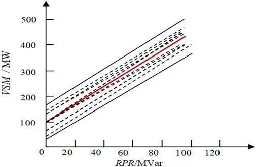
FIGURE 3. The relationship between RPR and VSM.
For the entire voltage control area, not all doubly-fed induction generators have adequate reactive power capability, only a reduced number of critical doubly-fed induction generators will be targeted to enhance the voltage stability margin. Experimental results have shown that the VSM of all systems is linearly related to the sum of critical RPRs as follows:
where
The goal of adjusting and managing the control quantity is to maintain the voltage level after disturbances through the least control actions and the reactive compensation. The solution of the convex quadratic control problem shown in Eq. 20 will determine the minimal amount of control actions needed to improve critical RPRs.
In Eq. 20,
Commonly, the reactive power reserve margin of the doubly-fed induction generators will not be reduced below the minimum value. Eq 21 gives the reactive power reserve limitation.
where
Equation 22 ensures that the amount of VSM will be raised above the minimum value.
In Eq. 23, bus voltage changes around the initial value can be easily impacted by the active power output, the capacitor compensation, and the active and reactive power of the load. Therefore, the voltage in Eq. 23 is considered to be expressed by the sum of the initial value
constraints of load reactive power removal respectivelywhere
By combining Eqs 20-28, an optimization problem is formed. The description of the method is shown in Figure 4.
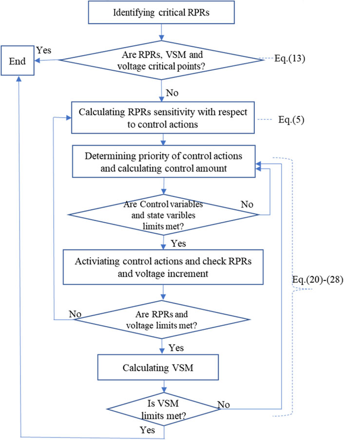
FIGURE 4. Flow chart for solving minimum control quantity.
It is assumed that the method converges under the condition that all limits are satisfied. If the VSM constraint is not satisfied, the process continues until it is converged. It needs to note that once the contingency cases increase, the number of constraints and variables increases. Hence, the computation of the optimization problem will increase significantly. Therefore, a fast and reliable solving method is important.
In this paper, an improved genetic algorithm (IGA) is used to solve the planning problem and search for the optimal control amount. The improved genetic algorithm includes the hybrid coding method for the improvement of coding, binary coding method is used for discrete control variables such as the transformer tap and the reactive power compensation switching of shunt capacitor group, and real coding method is used for continuous variables such as generator terminal voltage and load active and reactive power. To improve the initial population, an initial population with a quantity twice that of the traditional genetic algorithm (TGA) at random is generated in IGA, and then the fitness function value of all individuals in the population is calculated. Through comparison, the fitness function values are arranged in descending order, and half of the individuals with lower fitness function values are discarded. The other half of the individuals with higher fitness function values are taken as the initial population for subsequent iterative calculation. The initial population number obtained after improvement is the same as that of the TGA. However, the average value of the fitness function value of the newly generated population is higher, so that the convergence speed can be improved during power flow calculation. In order to avoid the local optimal solution and loss of population diversity caused by the premature maturity of excellent individuals, the quadratic fitness function value calculation method is adopted, by reducing the difference of fitness function values among individuals. After the first fitness function value is calculated, the average value of the fitness function value is calculated, and then the quadratic fitness function value is calculated. The implementation process of the improved genetic algorithm for the above multi-objective optimization problem is as follows:
Step 1: Obtaining the basic state value of power system by Newton Raphson power flow calculation;
Step 2: Determining the weak bus of the system and the compensation position of the parallel capacitor; then the preselected control variables are screened according to the RPR sensitivity.
Step 3: Starting the IGA, and coding the control variable and system state variable by using the binary code and real code, randomly generating double initial population;
Step 4: Calculating the fitness value of individuals in the initial population, retaining half of the individuals with larger fitness value, calculating the secondary fitness value, and selecting the excellent species group according to the results.
Step 5: Calculating the crossing probability and carry out the crossing operation; calculating the mutation probability and perform mutation operation;
Step 6: Recording the applied amount of various control variables, the increase amount of reactive power reserve margin, voltage and power and the increase of voltage stability margin calculated by the new species group;
Step 7: Making a judgment based on the three termination criteria in IGA. If any of the three criteria is met, continuing to step 8, or going back to step 2
Step 8: Outputting the minimum value imposed by the system control variables, reactive power reserve margin, voltage stability margin, and other state variable values.
The IEEE 39-bus system depicted in Figure 5 is adopted to test the proposed analytical approach. The algorithm is simulated by using PSASP software and consists of ten synchronous generators, 39 buses interconnected by 46 lines, and 12 transformers. Five DFIGs with a rated capacity of 150 MW each are integrated at five different buses without replacing the existing conventional units connected to them. The five bus numbers are 19, 20, 23, 25, and 29, respectively.
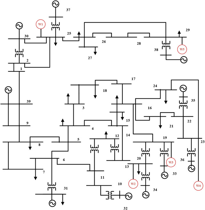
FIGURE 5. Structure Diagram of IEEE-39 bus system with DFIGs.
In the simulation process, only the RPRs at DFIG buses are calculated. Line 6-11 is assumed to suffer a three-phase-short-circuited fault at 0.5 s and is tripped at 0.7s. The reactive power distribution and voltage level in the system are changed. Voltage at bus 12 falls to about 0.9 p.u. Because the active power reduction of wind farm and load shedding tend to cause frequency oscillation and economic losses, the weight of these related control variables is set to 50%, and the weight factor values of all shunt capacitors are set to 100%. The TGA and IGA are applied to the IEEE-39 bus system for multi-objective optimization comparison:
1) Parameter settings of TGA: population size is 50, evolutionary generation is 120, crossover probability Pc = 0.5, mutation probability Pm = 0.01, and the maximum allowable number of iterations is 120.
2) Parameter setting of IGA: IGA is set according to the improved parameters used in (1). The initial population number is 50, the evolutionary generation is 120, the upper and lower limits of crossover probability are 0.9 and 0.6, and the upper and lower limits of mutation probability are 0.01 and 0.005.
The optimal solution obtained by the IGA and TGA is shunt capacitor compensation at bus 12 with 1.32 MVar. When the control is performed, Table 1 shows the comparison of VSM improvement and convergence generation between the TGA and IGA.
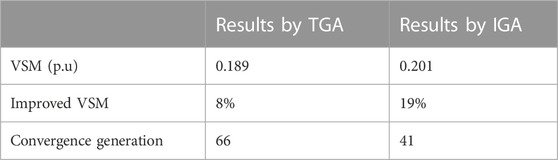
TABLE 1. Comparison with the TGA and IGA at bus 12 after reactive power control.
In Table 1, when the optimal solution is reached, the number of iterations of TGA is 66, while the number of iterations of IGA is 41, which is 25 times less than that of TGA, which indicates that IGA has a faster convergence speed. However, the VSM obtained by IGA is more than that by TGA. At the same time, the active power loss of the system (shown in Figure 6) is reduced from the initial value of 123 kw to 120.2 kw at the iteration ending.

FIGURE 6. The relationship between the total active power loss and iterations when bus 12 is compensated.
Then the loads in the load buses are increased until some bus is first approaching the collapse point, it is shown in Figure 7 that the RPRs of all the DFIGs are significantly reduced with Generator 3, 4 consuming almost all the RPRs and losing their voltage regulating capability, thus forming the critical RPRs and their minimum limits. To improve the critical RPRs, three kinds of control measures are investigated.
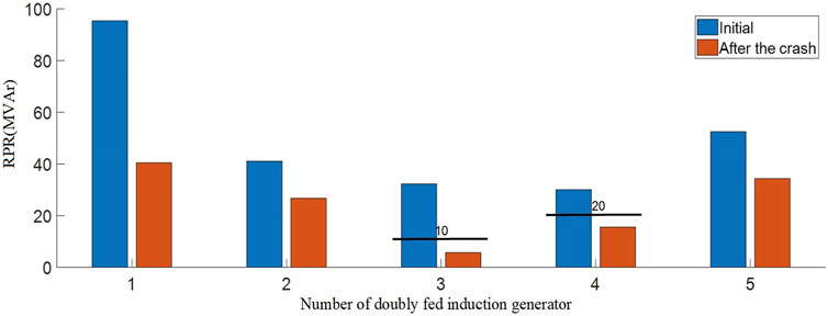
FIGURE 7. The change of RPR after the collapse.
According to the sensitivity data in Table 2, the reduction of the active power output can improve the RPR itself. The improvement is due to a significant increase in the amount of reactive power production. Moreover, reducing active power production tends to slightly improve the RPRs of the nearby units. In this case, the active power outputs
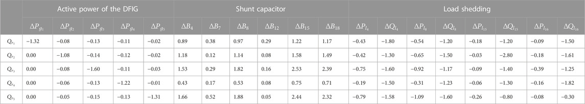
TABLE 2. sensitivity of rpr for three control measures.
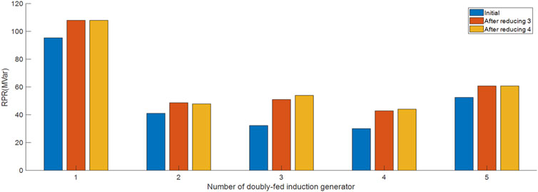
FIGURE 8. The effect of power generation reduction on RPR.
Shunt capacitors with low investment cost are the most common equipment to compensate reactive power and play an important role to achieve desirable voltage stability margin. The values of sensitivity in Table 2 show the improvement of reactive power reserves. The shunt capacitors are installed on the buses 4, 7, 8, 12, 15, and 18 and the maximum allowable shunt capacitance is limited to 20MVar. Improvements in RPRs are presented in Figure 9.
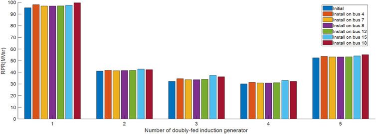
FIGURE 9. The effect of shunt capacitors on RPR.
Although load shedding is not often recommended, it can be used as the last resort to maintain the power balance and prevent voltage collapse. In the IEEE-39 bus system, the loads at buses 4, 7, 8, 15, and 16 are shed with a constant power factor. The control effect of load shedding is presented in Figure 10. It is shown that when the reactive load at bus 15 is removed, the reactive power reserve margin of DFIG 3 is increased from 32.3 MVar to 47.4 MVar.
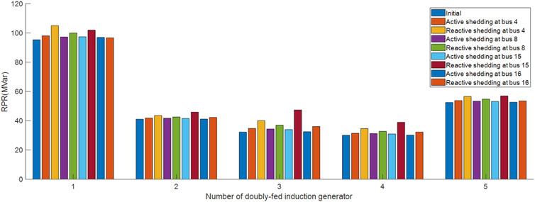
FIGURE 10. The effect of load shedding on RPR.
After each control variable is analyzed, all control variables will be tested together in a linear optimization problem and a few iterations are needed to achieve all imposed requirements. As mentioned before, the overall system VSM is linearly related to the sum of critical RPRs, and the value of the parameter k is 0.3112 by using the change of VSM to divide the sum of all the changes of critical RPRs.
Because generation shedding and load shedding can lead to frequency oscillations and economic losses, the weights associated with those variables are set to 50%, whereas the values of the weight factor of all shunt capacitors are still set to 1.0. To meet the requirements of RPRs and the limitation of VSM at the same time, two rounds of control measures have been implemented and the control actions for each round are shown in Table 3. According to the sensitivity priority, although 19 control variables are considered, only 14 control variables work to improve the VSM. Remarkably, there is a significant augment of reactive compensation on bus 18 and load shedding on buses 4 and 15. After iterations, when all the critical RPRs and control variables limits are met, the total amount of VSM is increased from 50.048 MW to 59.9896MW, with an increase of 19.9% as shown in Figure 11. In this process, the active power at the load is gradually increased and the active power of the DFIG is reduced, although this will slightly reduce voltage value at bus 12, it will be maintained at an appropriate stable value. The load center is often where the demand for reactive power is large. The implementation of reactive power compensation among the load center can effectively reduce the transmission of long distances of reactive power flow on the line, which has a direct and obvious effect on reducing the line loss. According to the principle of local balance of reactive power, buses 4, 7, 8, 12, 15, and 16 are determined as the compensation points. As seen from Figure 12, by applying control measures on the local key buses, not only the voltage stability of these key vulnerable buses is significantly improved, but also the voltage stability of the whole system is improved to a certain extent.
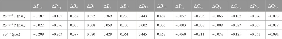
TABLE 3. The minimum quantity of control variable.
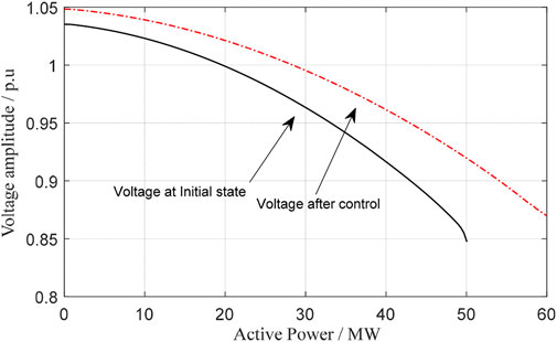
FIGURE 11. VSM enhancement after the minimum control is applied.
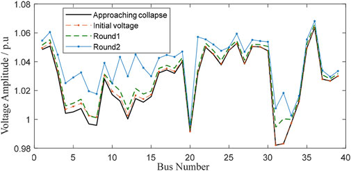
FIGURE 12. Bus Voltage enhancement after two rounds of control.
Table 4 shows the comparison of improved voltage stability between the TGA and the IGA. Because the intersection rate and variation rate of the traditional genetic algorithm remains constant, the convergence speed of the algorithm is slow, and the problem of premature convergence often occurs. To solve this problem, the modified adaptive genetic algorithm is adopted. When the optimization process falls into the trend of the local optimal solution, the intersection rate and variable rate are increased and when the group tends to diverge in the solution space, the intersection rate and variation rate are reduced. The simulation results show that the total CPU time for IGA to calculate the two rounds of control measures for the IEEE-39 Bus system is approximately 15 s while the running time of the TGA is 32 s. The total time estimates include the PV curve, sensitivity, and optimization calculations.
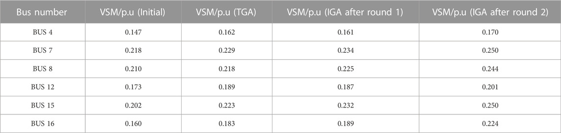
TABLE 4. Effect of Control measures on Voltage Stability margin of fragile bus.
In this paper, a method based on convex quadratic programming is proposed to coordinate different reactive power reserves for improved voltage stability margin of the power system with DFIG wind farms.Built upon the control mechanism of reactive power reserve in a doubly-fed induction generator, three main control measures, i.e., DGIG control, shunt capacitor banks, and load shedding, are proposed and compared to improve the RPRs to maintain system voltage stability and the results show that the reduced power generation of DGIG can both improve its reactive power reserve and the RPR of the other units, which makes it more suitable to provide the reactive power reserves for voltage stability.To fully unlock the value of the DGIG wind farms, the sensitivity method is used to detect and remove the unnecessary control variables, which further reduces the dimension and complexity of the convex quadratic programming problem for voltage control. The improved genetic algorithm is used to solve the proposed convex quadratic programming problems. Compared with the traditional genetic algorithm, the IGA has a shorter operation time without sacrificing the accuracy of the results. Further research should be focused on implementing additional control variables and applying them to larger networks.
The original contributions presented in the study are included in the article/supplementary material, further inquiries can be directed to the corresponding author.
QL is responsible for the whole idea and the deduction of the method; YS is responsible for the simulation; YJ is responsible for the algorithm verification,English writing and improvements; YX is responsible for the modify the thoery analysis of CVC; SC is responsible for the verification and analysis of the simulation.
The authors declare that the research was conducted in the absence of any commercial or financial relationships that could be construed as a potential conflict of interest.
All claims expressed in this article are solely those of the authors and do not necessarily represent those of their affiliated organizations, or those of the publisher, the editors and the reviewers. Any product that may be evaluated in this article, or claim that may be made by its manufacturer, is not guaranteed or endorsed by the publisher.
De, M., and Goswami, S. (2014). Optimal reactive power procurement with voltage stability consideration in deregulated power system. IEEE Trans. Power Syst. 29 (5), 2078–2086. doi:10.1109/tpwrs.2014.2308304
Ding, T., Liu, S., Yuan, W., Bie, Z., and Zeng, B. (2016). A two-stage robust reactive power optimization considering uncertain wind power integration in active distribution networks. IEEE Trans. Sustain. Energy 7 (01), 301–311. doi:10.1109/tste.2015.2494587
Dong, F., Chowdhury, B. H., Crow, M. L., and Acar, L. (2005). Improving voltage stability by reactive power reserve management. IEEE Trans. Power Syst. 20 (01), 338–345. doi:10.1109/tpwrs.2004.841241
El-Araby, E. S. E., and Yorino, N. (2018). Reactive power reserve management tool for voltage stability enhancement. IET Generation, Transm. Distribution 12 (8), 1879–1888. doi:10.1049/iet-gtd.2017.1356
Gabash, A., and Li, P. (2012). Active-reactive optimal power flow in distribution networks with embedded generation and battery storage. IEEE Trans. Power Syst. 27 (4), 2026–2035. doi:10.1109/tpwrs.2012.2187315
Ghosh, S., Isbeih, Y., Bhattarai, R., Mohamed, S., Ehab, F. E., and Sukumar, K. (2020). A dynamic coordination control architecture for reactive power capability enhancement of the DFIG-based wind power generation. IEEE Trans. Power Syst. 35 (04), 3051–3064. doi:10.1109/tpwrs.2020.2968483
Grudinin, N. (1998). Reactive power optimization using successive quadratic programming method. IEEE Trans. Power Syst. 13 (4), 1219–1225. doi:10.1109/59.736232
Han, T., Chen, Y., Ma, J., Zhao, Y., and Chi, Y. (2018). Surrogate modeling-based multi-objective dynamic VAR planning considering short-term voltage stability and transient stability. IEEE Trans. Power Syst. 33 (1), 622–633. doi:10.1109/tpwrs.2017.2696021
Hu, B., Niu, T., Li, F., Xie, K., Li, W., and Jin, H. (2021). Dynamic var reserve assessment in multi-infeed LCC-HVDC networks. IEEE Trans. Power Syst. 36 (01), 68–80. doi:10.1109/tpwrs.2020.3008491
Huang, S., Wu, Q., Zhao, J., and Liao, W. (2020). Distributed optimal voltage control for VSC-hvdc connected large-scale wind farm cluster based on analytical target cascading method. IEEE Trans. Sustain. Energy. 11 (04), 2152–2161. doi:10.1109/tste.2019.2952122
Ibrahim, T., Tomas Rubira, T., Rosso, A., Patel, M., Guggilam, S., and Mohamed, A. (2022). Alternating optimization approach for voltage-secure multi-period optimal reactive power dispatch. IEEE Trans. Power Syst. 37 (5), 3805–3816. doi:10.1109/tpwrs.2021.3133358
Jankowski, R., Kosmecki, M., and Kubanek, A. (2017). Novel voltage stability assessment method based on reactive power reserve measurements[C]//Proceedings of the 2017 11th IEEE International Conference on Compatibility, Power Electronics and Power Engineering (CPE-POWERENG). IEEE, Cadiz, Spain 65–70.
Leonardi, B., and Ajjarapu, V. (2012). An approach for real time voltage stability margin control via reactive power reserve sensitivities. IEEE Trans. power Syst. 28 (2), 615–625. doi:10.1109/tpwrs.2012.2212253
Li, Y., Zhao, J., Liu, Z., Li, P., Zhang, X., and Tang, X., (2013). Proceedings of the IEEE international conference of IEEE region 10 TENCON 2013). IEEE, 1–4. Xi'an, China. Assessment method of dynamic reactive power valuation for transient voltage stability.
Ma, H., Wang, G., Gao, X., Zou, Z., and Dong, Y. (2022). An adaptive voltage control using local voltage profile mode and similarity ranking. Front. Energy Res. 10, 1–12. doi:10.3389/fenrg.2022.865151
Mugemanyi, S., Qu, Z., Rugema, F., Dong, Y., Bananeza, C., and Wang, L. (2020). Optimal reactive power dispatch using chaotic bat algorithm. IEEE ACCESS 8, 65830–65867. doi:10.1109/access.2020.2982988
Oliveira, R. A., and Bollen, M. H. J. (2022). Susceptibility of large wind power plants to voltage disturbances–recommendations to stakeholders. J. Mod. Power Syst. Clean Energy 10 (2), 416–429. doi:10.35833/mpce.2020.000543
Ouyang, J., Tang, T., Yao, J., and Li, M. (2019). Active voltage control for DFIG-based wind farm integrated power system by coordinating active and reactive powers under wind speed variations. IEEE Trans. Energy Convers. 34 (3), 1504–1511. doi:10.1109/tec.2019.2905673
Park, B., Im, S., Kim, D., and Lee, B. (2021). Clustered effective reactive reserve to secure dynamic voltage stability in power system operation. IEEE Trans. Power Syst. 36 (2), 1183–1192. doi:10.1109/tpwrs.2020.3020119
Qinyu, B., Lin, Y., Jiayi, M., Lu, T., and Youyin, W. (2018). Proceedings of the China international conference on electricity distribution (CICED). IEEE,Tianjin, China 2029–2033.Analysis of influence with connected wind farm power changing and improvement strategies on grid voltage stability
Ren, X., Wang, H., Wang, Z., Wang, Q., Li, B., Wu, H., et al. (2022). Reactive voltage control of wind farm based on tabu algorithm. Front. Energy Res. 10, 1–8. doi:10.3389/fenrg.2022.902623
Sissine, F. (2007). Energy independence and security act of 2007: A summary of major provisions. Washington, DC, USA: Congressional Research Service, the Library of Congress.
Sun, Q., Cheng, H., and Song, Y. (2017). Bi-objective reactive power reserve optimization to coordinate long-and short-term voltage stability. IEEE Access 6, 13057–13065. doi:10.1109/access.2017.2701826
Keywords: reactive power reserve, voltage stability margin, convex quadratic programming problem, wind power, power system
Citation: Liu Q, Song Y, Jiang Y, Xu Y and Chen S (2023) Coordinated voltage control for improved power system voltage stability by incorporating the reactive power reserve from wind farms. Front. Energy Res. 10:1088563. doi: 10.3389/fenrg.2022.1088563
Received: 03 November 2022; Accepted: 19 December 2022;
Published: 06 January 2023.
Edited by:
Liansong Xiong, Xi'an Jiaotong University, ChinaReviewed by:
Ning Li, Xi'an University of Technology, ChinaCopyright © 2023 Liu, Song, Jiang, Xu and Chen. This is an open-access article distributed under the terms of the Creative Commons Attribution License (CC BY). The use, distribution or reproduction in other forums is permitted, provided the original author(s) and the copyright owner(s) are credited and that the original publication in this journal is cited, in accordance with accepted academic practice. No use, distribution or reproduction is permitted which does not comply with these terms.
*Correspondence: Qunying Liu, lqy1206@126.com
Disclaimer: All claims expressed in this article are solely those of the authors and do not necessarily represent those of their affiliated organizations, or those of the publisher, the editors and the reviewers. Any product that may be evaluated in this article or claim that may be made by its manufacturer is not guaranteed or endorsed by the publisher.
Research integrity at Frontiers
Learn more about the work of our research integrity team to safeguard the quality of each article we publish.