 Sahib Ullah1
 Sarmad Majeed Malik1*Yingyun Sun2Muhammad Numan3Mansoor Asif4Junjie Hu2Muhammad Kamran Bodla5
- 1Department of Electrical Engineering, College of Electrical and Mechanical Engineering (CEME), National University of Sciences and Technology (NUST), Islamabad, Pakistan
- 2State Key Laboratory of Alternate Electrical Power System with Renewable Energy Sources, Department of Electrical Engineering, North China Electric Power University (NCEPU), Beijing, China
- 3Department of Electrical Engineering, US-Pakistan Center for Advanced Studies in Energy (USPCAS-E), National University of Sciences and Technology (NUST), Islamabad, Pakistan
- 4Department of Electrical Engineering, School of Electrical Engineering and Computer Science (SEECS), National University of Sciences and Technology (NUST), Islamabad, Pakistan
- 5Department of Electrical Engineering, Shanghai Jiao Tong University (SJTU), Shanghai, China
Renewable energy sources tied to a utility grid require non-linear control algorithms to provide an efficient and stable output under different operating conditions. The maximum power point tracking (MPPT) approach is necessary for power generation due to non-linear behavior of photovoltaic (PV) power plants. In changing environmental and partial shading conditions, the standard MPPT methods may lead to abnormal results. In this paper, a backstepping based real twisting sliding mode MPPT control is proposed for the PV-battery system where maximum available power is extracted by tracking PV voltage. Moreover, a direct sliding mode control is proposed for battery-integrated buck boost converter for voltage regulation. Reference sliding surface is generated through linear interpolation based on the predicted maximum power point PV voltage. The proposed MPPT strategy is tested against variations of irradiance, temperature, and load. Simulation results highlight superior tracking performance, reduced chattering, and oscillations of this technique over existing models.
1 Introduction
Renewable energy sources appear as the best solution for worldwide power shortage and environmental pollution. In particular, the focus is on solar as it offers inexhaustible, clean and free energy which is abundantly available at various parts of the world. The demand of photovoltaic (PV) is also increasing as solar energy is deployed for residential and industrial purposes (Rajabi et al., 2022). In this regard, the optimization of solar power generation is important as it reduces system operational cost and number of PV panels and improves system efficiency. This is achieved through maximum power point tracking (MPPT) algorithm that ensures maximum output PV power under varying conditions (Millah et al., 2021).
With an increased rate of utilization of PV, researchers have focused on developing new MPPT techniques to extract maximum power from the PV system. Different MPPT methodologies have been introduced which can be broadly categorized as metaheuristic optimization, control law based MPPT, and machine learning based MPPT techniques. Machine learning based radial basis function neural network (RBNN) has been proposed in (Khan et al., 2021), which has a fast convergence but cannot accommodate continuous chattering as neural network needs continuous training. Genetic algorithm (GA) based MPPT with an artificial neural network (ANN) has also been proposed for MPPT which demonstrated reasonable tracking speed and DC power output (Ali et al., 2018). However, this technique is difficult to implement due to complexity arising from increased system dynamics. ANN based MPPT approach for PV electric vehicle is studied in (Bhatia et al., 2020) where open circuit voltage and temperature of solar cell were used as input variables while MPP voltage was the output variable. In addition to ANN and GA, fuzzy logic controller is also used for PV systems which is relatively easy to design since knowledge of an accurate MPPT model is not required (Dehghani et al., 2021). However, continuous training and high-error susceptibility are major issues. Conventional perturb and observe (P&O) strategy is also used for MPPT control due to its fast convergence and simplicity (Ahmed and Salam, 2018). In general, machine learning MPPT techniques achieve high efficiency, fast convergence and reduced oscillations but are costly and computationally extensive. Moreover, the systems cannot capture partial shading condition (PSC) under global MPP.
To deal with the issue of PSC, bio-inspired metaheuristic optimization based techniques are employed. Shuffled frog algorithm has been proposed in (Aldosary et al., 2021) to address this anomaly and improve MPPT controller for battery integrated PV system but the technique is inefficient under rapidly changing atmospheric conditions. Hybrid whale optimization algorithm has been discussed in some literature which has a high efficiency but it requires accurate data set and works for finite time limits (Tao et al., 2021). Although the metaheuristic techniques have various advantages, none of these optimizers address optimization problem with different constraints (Shams et al., 2021). In fact, existing research has examined the optimizers for a single or few patterns of irradiance without comprehensive statistical analysis. For instance, the gray wolf optimizer in (Jegha et al., 2020) has shown tracking accuracy under a certain set of irradiance while the impact of temperature is neglected. Dragonfly and adaptive cuckoo search optimization are presented in (Mirza et al., 2019) where variations are proposed to reference voltage for rapid global convergence among multiple PV systems. The performance of all metaheuristic optimization-based MPPT strategies is dependent on population size, number of iterations, convergence speed and effectiveness of the information sharing method.
Closed-loop MPPT control strategies aim to overcome the shortcoming of computational complexity offered by metaheuristic optimization techniques. Non-linear closed-loop schemes have been widely used in PV systems. A robust non-linear backstepping controller (BSC) for MPPT tracking is analyzed in (Ali et al., 2020), which relies on reference power generation through neuro-fuzzy approach. This system is designed for a single irradiance value and requires re-training as irradiance changes. A similar technique is discussed in (Awais et al., 2020) where the non-linear controller is linearized for a certain field data. However, this scheme is infeasible for practical PV systems which experience constantly changing environmental conditions. Sliding mode control (SMC) is one of the widely employed non-linear closed-loop method which offers various advantages such as disturbance rejection, parameter variation insensitivity and decoupled design (Aguilar et al., 2019). SMC can overcome the issue of uncertainty limits to an extent. In the presence of large uncertainties, controller gain has to be increased which enhances chattering effect (Skik and Abbou, 2016). Backstepping terminal sliding mode (BTSM) controller is discussed in (Behih and Attoui, 2021) to extract maximum power of PV system. However, it can only track MPPT curve and fails to provide controlled compensation to variations in irradiance and temperature. Non-linear control law based double integral sliding mode controller is studied in (Pradhan and Subudhi, 2016) which reduces the steady state error of MPPT through an integral component. This error reduction is at the expense of distorted transient response with increased chattering. Second order sliding mode MPPT controller has also been studied in some literature but it generates inaccurate reference current and hence, an inaccurate optimal power extraction (Peng et al., 2019). A comparison of these control techniques is highlighted in Table 1.
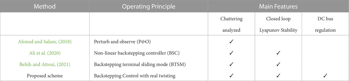
TABLE 1. Comparison of control schemes of PV system.
This paper presents a robust non-linear backstepping based real twisting sliding mode control for MPP tracking in PV battery systems. In the proposed scheme, the regression plane is generated by the predicted maximum power point voltage using linear interpolation which gives high accuracy. Contrary to other autonomous schemes which deploy droop control for DC bus voltage regulation, in this paper, a direct sliding mode control is proposed which helps regulate voltage under varying irradiance, temperature and loads. The system topology consisting of PV, battery, boost, and buck-boost converter is simulated and analyzed in MATLAB where it is observed that the proposed scheme has a good tracking with reduced overshoot, chattering and settling time. The optimal performance of the proposed control is also highlighted in comparison with other well-established control strategies.
The rest of the paper is organized as follows: Section 2 discusses the system topology and converter control. Section 3 presents back stepping based real twisting sliding mode control while the power management and parameter design are analyzed in Section 4. Simulation results and discussion are given in Section 5, followed by conclusion in Section 6.
2 System topology and converter control
The system topology consists of PV module and battery linked to DC bus via buck-boost converters. This is shown in Figure 1. The battery buck-boost converter is bidirectional and can operate in either buck or boost mode depending on the current drawn from the source. It consists of two loops: an outer voltage control loop with PI controller and an inner current control using SMC. This helps regulate the DC bus voltage. Linear interpolation-based regression plane is employed to generate the reference voltage signal for PV. The modeling of PV and buck-boost converters along with the control schemes are discussed as follows.
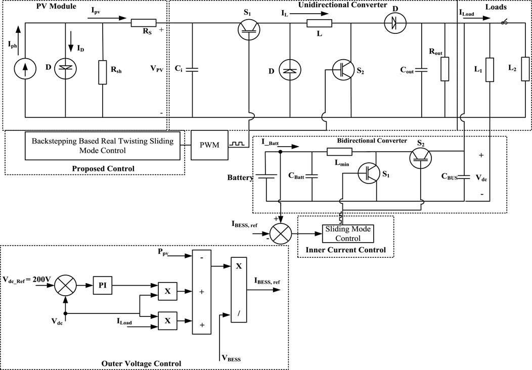
FIGURE 1. Photovoltaic battery connected system under consideration.
2.1 PV module modeling
The PV module consists of solar cells connected in series and parallel. Series connection gives the required voltage output while parallel connection increases output current. Different models of solar cells are used in PV system such as single diode, double diode and three diode model. Single diode model is commonly used due to its simplicity while double and three diode models are treated as industrial models and are used for specific applications. In this paper, single diode model is considered which is shown in Figure 2.
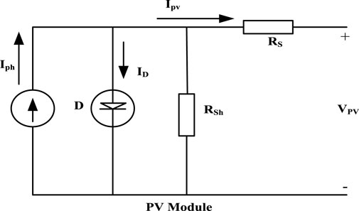
FIGURE 2. Single diode mode.
The current produced in the solar cell is directly proportional to light intensity and the output current of PV can be expressed as (Ibrahim and Anani, 2017):
The output voltage V of the module is the product of voltage of single cell and the number of cells. Thus, the short circuit current is given as:
where a positive value of Ki indicates an increase in short circuit current with temperature. The open circuit voltage of PV is expressed as:
where a negative value of Kv indicates that as the temperature rises, the open circuit voltage decreases. The maximum current and voltage of solar cell array is represented as (Ibrahim and Anani, 2017):
The PV panel characteristic for different values of temperature and irradiance is shown in Figures 3, 4, respectively. It can be observed that the output current marginally rises with increasing temperature. However, the open circuit voltage drops. Irradiation variations have a significant impact on the short circuit voltage but a negligible impact on the open circuit voltage. The oscillation of the MPP is therefore dependent on solar irradiation (Rehman et al., 2020).
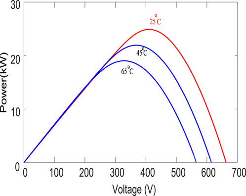
FIGURE 3. PV Curve with temperature variations.

FIGURE 4. PV Curve with irradiance variations.
2.2 Buck boost converter modeling
From inductor volt second balance and capacitor charge balance, we have:
The input and output resistance of converter Rin and RL follow the relation:
Averaging across a switching period yields state space equations for control design as:
3 Proposed backstepping based real twisting sliding mode control
The first step in controller design involves calculations of error between actual and desired PV output voltage. Thus, ɛ1 defined as the difference between actual and expected output voltage of a solar PV system:
where α1ref is the reference PV voltage. Combining (11) and (14), we have:
To reduce error signal to zero, we need to treat α2 as a virtual control input which should satisfy Lyapunov stability theory. Thus, the time derivative of Lyapunov term
The constant K1 in (17) must be a positive constant for any specific x2. Hence, (16) can be rewritten as:
The stabilization function acts as a reference for x2 as:
The second state needs a new reference for further tracking. In this regard,
Solving (16) and (19) leads to:
Substituting (19) in (21), we have:
Differentiating (20) with respect to time leads to:
Therefore, the time derivative of
where
To ensure convergence of errors ɛ1 and ɛ2 to zero, a composite Lyapunov function Vc is defined as:
The time derivative of Vc is given as:
For Vc to be negative, let:
which can be expanded as:
Thus, the backstepping based equivalent control law becomes:
This control law modifies (27) to an alternate form as:
where 0 < μ < 1 and α2ref ≠ 0.
From (31), it can be observed that the derivative of Lyapunov function is negative definite. Therefore, the design of proposed controller is globally asymptotically stable.
The Real twisting sliding mode-based discontinuous control Law is designed as (Bjaoui et al., 2019):
The modified control law is used for mitigating chattering effect in higher order non-linear system. The proposed backstepping based real twisting sliding mode control law, is given as:
The proposed algorithm in this paper uses a continuous control function that drives the sliding variable and its derivative to zero in finite time. By twisting the state trajectories around the origin, convergence independent of constrained perturbations is achieved that retains good performance despite variations and uncertainties. The flow chart of algorithm is shown in Figure 5.
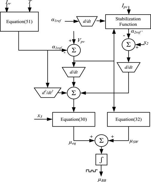
FIGURE 5. Flow chart of proposed BRTA algorithm.
4 Power flow management
Bidirectional buck-boost converters can operate in buck mode or boost mode depending on the power flow direction. Two control modes need to be deployed to operate the converter in desired mode of operation and based on the battery current direction, required mode should be triggered. It is worth mentioning that the objective of both modes is to regulate DC bus voltage.
In the battery control, outer voltage loop produces the current reference for inner current control. Assuming negligible losses in the system, the dc current can be expressed as:
Battery current IBESS is used to regulate Idc to its reference Idc,ref. Hence, (34) can be written as:
The sliding surface for the inner current loop of battery controller is chosen as:
The battery current and DC bus voltages reach their reference values in a finite time. Correspondingly, SMC controls PWM signal which is used in buck and boost modes.
4.1 Buck mode operation
The duty cycle in the buck mode can be expressed as:
The battery current is given as:
Considering (36) and (37) with μBuck = 0, δ > 0, we have:
When δ < 0 and μBuck = 1, we have:
Thus, the sliding surface δ = 0 is finite time attractive.
4.2 Boost mode operation
The duty cycle in the boost mode is given as:
while the battery current is:
Considering (36) and (41) with μBoost = 0, δ < 0, we have:
When δ > 0 and μBoost = 1, we have:
For sliding mode to exist in (36), the sliding condition
4.3 Parameter design of unidirectional buck-boost converter
The duty cycle of buck-boost converter is dependent on input and output voltage as:
The value of inductor L can be derived from switching time period T, voltage drop across diode Vd1 and output current Iout as:
The value of capacitance C is obtained as:
4.4 Parameter design of bidirectional buck-boost converter
For non-inverting buck-boost converters, the model is designed to work in continuous conduction mode (CCM). Since the converter has two modes of operation, the design is identical to buck and boost converters.
The minimum value of inductance to ensure CCM operation, for both buck and boost modes, is calculated as:
In (48), a value of 33 is used for μ which corresponds to maximum value solution and maintains CCM. The dc bus capacitor filters the ripples in voltage and its value is selected as:
The size of battery capacitor can be determined as:
5 Simulation results and discussion
To analyze the proposed control scheme, the system in Figure 1 is built in Simulink. The DC bus voltage is 200 V while the PV system has maximum power rating of 25 kW with solar irradiance 1000 W/m2 and operating temperature of 298K/25°C. The system parameters are obtained from (45–50) and are highlighted in Table 2 where (K1, K2, K3, K4, K5) are gains of BRTA while (K6, K7) are gains of SMC, respectively.
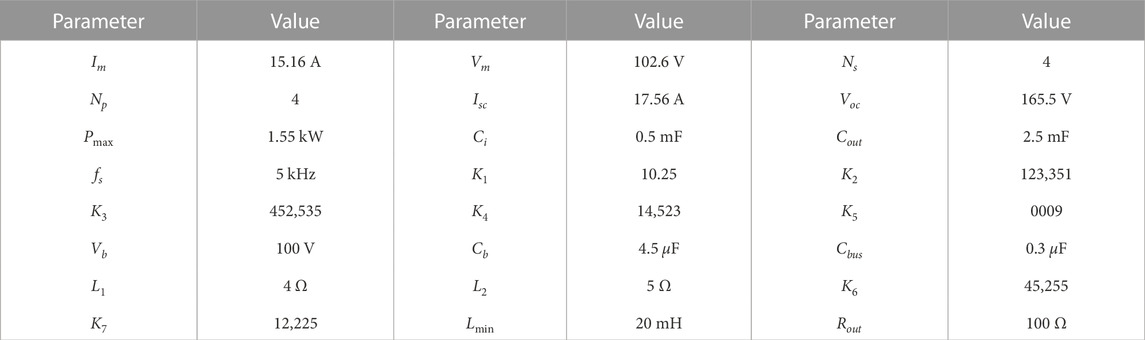
TABLE 2. System parameters and initial conditions.
The PV panel regression plane is shown in Figure 6. It provides a reference voltage for the non-linear controller to achieve MPP under fluctuating temperature and irradiance conditions. The PV module characteristic curve is used to build the Vmpp matrix for various temperature and irradiance levels. The regression plane is obtained via linear interpolation, which gives the reference voltage, α1ref, to the controller. To achieve MPP, the backstepping based real twisting controller follows reference voltage α1ref as:
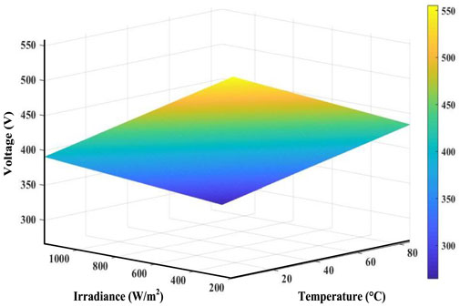
FIGURE 6. Regression plane.
At initial steady state, PV panel is producing 25 kW and load power consumption is 10 kW. The battery is in charging mode with 15 kW. The control law in (33) determines the desired PV voltage while BRTA extracts maximum power point by tracking the desired PV voltage obtained by linear regression method. System performance is studied through the following changes.
1) The irradiance of PV panel varies from 1000 W/m2 to 850 W/m2 at t = 1 s.
2) The PV temperature is increased from 25°C to 45°C at t = 2 s.
3) Simultaneous change of temperature and irradiance is observed at t = 3 s. In this regard, temperature is raised from 45°C to 65°C and irradiance drops from 850 W/m2 to 650 W/m2.
4) The PV system load is increased by 8 kW at t = 4 s.
5.1 Change in irradiance
The suggested MPPT controller’s performance is first validated using an irradiance variation. At t = 1 s, the irradiance of PV panel is reduced from 1000 W/m2 to 850 W/m2. Following this change, the PV power falls from 25 kW to 23 kW which can also be confirmed from product of (4) and (5). This is shown in Figure 7. Since the load is constant, the active power used to charge battery changes from 15 kW to 13 kW. It should be noted that the negative power in Figure 7 signifies charging operation of battery.

FIGURE 7. Power profiles of battery, load, and PV.
Based on the measured values of temperature and irradiance, the reference PV voltage waveform is shown in Figure 8. It can be seen from Figure 9 that the proposed controller successfully tracks the reference voltage during irradiance variation. In this regard, the settling time is 005 s and rise time is 003 s. The system has a good dc bus voltage regulation at 200 V which is highlighted in Figure 10.
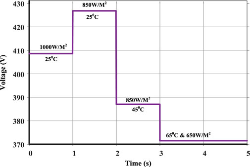
FIGURE 8. Maximum peak power reference voltage.
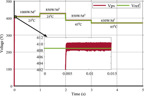
FIGURE 9. PV voltage tracking.

FIGURE 10. DC bus voltage variation.
5.2 Change in temperature
The PV system observes a temperature variation from 25°C to 45°C at t = 2 s. As shown in Figure 3, for the same voltage, the power produced by PV decreases with increase in temperature. This is highlighted in Figure 7 where the PV power reduces by 3 kW. Correspondingly, the battery overcomes the power shortage to the load by discharging 3 kW and maintaining constant load power. During this change, the proposed controller is constantly tracking the reference PV voltage with reduced chattering and fast convergence as highlighted in Figure 9. It can also be observed from Figure 10 that the voltage variations of DC bus are minimal, signifying good performance of the scheme.
5.3 Simultaneous change in temperature and irradiance
The PV system can also experience simultaneous variations in temperature and irradiance and this scenario is simulated at t = 3 s. At this instant, temperature increases from 45°C to 65°C while irradiance decreases from 850 W/m2 to 650 W/m2. These variations have a combined effect of reducing the PV power from 20 kW to 14 kW as apparent from preceding discussion and shown in Figure 7. Since the load is constant, the battery discharges to ensure same power supply to load. The reference PV voltage variation is shown in Figure 8 where it can be observed that the temperature and irradiance variations force the reference voltage to change from 387 V to 372 V. The controller maintains its voltage tracking capability with minimum overshoot. Moreover, the DC bus voltage is still maintained at reference value. This is given in Figures 9, 10.
5.4 Change in load
At t = 4 s, the load of the PV system is increased by 8 kW. During this change, the irradiance and temperature are kept constant and hence, the PV output power is maintained at 14 kW. To satisfy the new load, battery discharging power rises by 8 kW. This is evident from Figure 7. As shown in Figure 8, the reference generated PV voltage by controller remains same as there is no change in temperature and irradiance. The controller is successfully tracking the PV voltage highlighted in Figure 9. The reference dc bus voltage profile observes a sharp dip of around 1 V which is well-within the voltage regulation limit. This is shown in Figure 10. All the simulated scenarios highlight the optimal performance of the control scheme under different conditions of temperature, irradiance and load.
5.5 Comparison of proposed scheme with other schemes
In this section, the proposed PV controller is compared with prevalent MPPT tracking algorithms such as P&O, BSC and BTSM. Different environmental conditions are used with variations in temperature and irradiance. The voltage comparison of the techniques is shown in Figure 11. It can be observed that the proposed BRTA controller achieves steady state in 005 s compared to BTSM which achieves the steady state in 01 s. The BRTA controller has fast rise time, superior tracking performance and achieves MPP rapidly with no overshoot compared to P&O. No chattering is observed in proposed technique compared to BSC and BTSM controllers. On the other hand, BSC control strategy shows steady state error in MPP tracking and minimal tracking performance during fluctuations in atmospheric condition. Detailed voltage profile comparison is shown in Table 3.
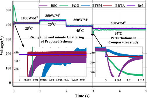
FIGURE 11. Voltage tracking comparison.

TABLE 3. Comparison of PV voltage tracking.
For each control strategy, comparison of PV array output power is shown in Figure 12. The BRTA tracking performance is better during temperature and irradiance fluctuations in terms of fast convergence, rise time and reduced chattering. The results show that the proposed controller is reliable, more robust and has a faster response during atmospheric fluctuations. Moreover, it ensures a seamless, stable operation with battery connected system which makes it ideal for future power systems.
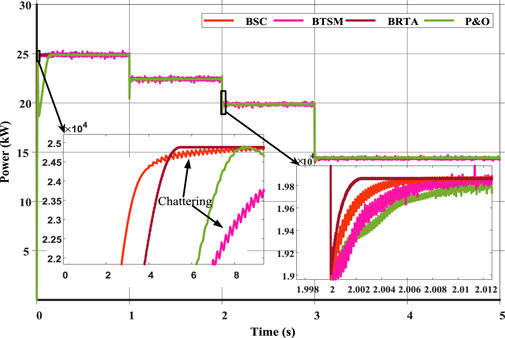
FIGURE 12. Maximum power comparison.
6 Conclusion and future work
This paper presents a robust non-linear backstepping based real twisting sliding mode control for MPP tracking in PV battery systems. In the proposed scheme, the regression plane is generated by the predicted maximum power point voltage using linear interpolation which gives high accuracy. Contrary to other autonomous schemes which deploy droop control for DC bus voltage regulation, in this paper, a direct sliding mode control is proposed which helps regulate voltage under varying irradiance, temperature and loads. The system topology consisting of PV, battery, boost, and buck-boost converter is simulated and analyzed in MATLAB where it is observed that the proposed scheme has a good tracking with reduced overshoot, chattering and settling time. The optimal performance of the proposed control is also highlighted in comparison with other well-established control strategies, making it an ideal candidate for future PV-battery systems.
For future work, the proposed scheme can be integrated with machine learning techniques to further improve the system performance. The system can be expanded to include AC and DC sources to analyze dynamics. Moreover, the hardware prototype should be developed to ensure coherence between simulated and measured values.
Data availability statement
The datasets presented in this article are not readily available because they are under the authority of corresponding author’s university. Requests to access the datasets should be directed to c2FybWFkbWFsaWs5MEBnbWFpbC5jb20=.
Author contributions
All authors listed have made a substantial, direct, and intellectual contribution to the work and approved it for publication.
Funding
This study is supported by the State Key Laboratory of Alternate Electrical Power System with Renewable Energy Sources, North China Electric Power University, Beijing, China (Grant No. LAPS21017).
Conflict of interest
The authors declare that the research was conducted in the absence of any commercial or financial relationships that could be construed as a potential conflict of interest.
Publisher’s note
All claims expressed in this article are solely those of the authors and do not necessarily represent those of their affiliated organizations, or those of the publisher, the editors and the reviewers. Any product that may be evaluated in this article, or claim that may be made by its manufacturer, is not guaranteed or endorsed by the publisher.
References
Aguilar, P. V., Espinoza-Trejo, D. R., Saavedra, J. L., De Angelo, C. H., and Taheri, S. (2019). “Nonlinear control of a boost DC/DC converter for photovoltaic MPPT systems using a TMS320F28379D microcontroller,” in 2019 IEEE 7th International Conference on Smart Energy Grid Engineering (SEGE), Oshawa, ON, Canada, 12-14 August 2019, 156–161.
Ahmed, J., and Salam, Z. (2018). An enhanced adaptive (P&O) MPPT for fast and efficient tracking under varying environmental conditions. IEEE Trans. Sust. Energy. 9 (3), 1487–1496. doi:10.1109/tste.2018.2791968
Aldosary, A., Ali, Z. M., Alhaider, M. M., Ghahremani, M., Dadfar, S., and Suzuki, K. (2021). A modified shuffled frog algorithm to improve MPPT controller in PV System with storage batteries under variable atmospheric conditions. Control Eng. Pract. 112, 104831. doi:10.1016/j.conengprac.2021.104831
Ali, K., Khan, Q., Ullah, S., Khan, I., and Khan, L. (2020). Nonlinear robust integral backstepping based MPPT control for stand-alone photovoltaic system. PLOS ONE 15 (5), e0231749. doi:10.1371/journal.pone.0231749
Ali, M. N., Mahmoud, K., Lehtonen, M., and Darwish, M. M. F. (2018). Promising MPPT methods combining metaheuristic, fuzzy-logic and ANN techniques for grid-connected photovoltaic. Sensors 21 (4), 1244. doi:10.3390/s21041244
Awais, M., Khan, L., Ahmad, S., Mumtaz, S., and Badar, R. (2020). Nonlinear adaptive NeuroFuzzy feedback linearization based MPPT control schemes for photovoltaic system in microgrid. PLOS ONE 15 (6), e0234992. doi:10.1371/journal.pone.0234992
Behih, K., and Attoui, H. (2021). Backstepping terminal sliding mode MPPT controller for photovoltaic systems. Eng. Technol. Appl. Sci. Res. 11 (2), 7060–7067. doi:10.48084/etasr.4101
Bhatia, P., Mittal, S., Raizada, S., and Verma, V. (2020). “Hybrid ANN based incremental conductance MPPT-current control algorithm for constant power generation of PV fed DC microgrid,” in IEEE First International Conference on Smart Technologies for Power, Energy and Control (STPEC), Nagpur, India, 25-26 September 2020, 1–7.
Bjaoui, M., Khiari, B., Benadli, R., Memni, M., and Sellami, A. (2019). Practical implementation of the backstepping sliding mode controller MPPT for a PV-storage application. Energies 12 (18), 3539. doi:10.3390/en12183539
Dehghani, M., Taghipour, M., Gharehpetian, G. B., and Abedi, M. (2021). Optimized fuzzy controller for MPPT of grid-connected PV systems in rapidly changing atmospheric conditions. Jour. Mod. Power Syst. Clean Energy. 9 (2), 376–383. doi:10.35833/mpce.2019.000086
Ibrahim, H., and Anani, N. (2017). Variations of PV module parameters with irradiance and temperature. Energy Procedia 134, 276–285. doi:10.1016/j.egypro.2017.09.617
Jegha, A. D. G., Subathra, M. S. P., Kumar, N. M., Subramaniam, U., and Padmanaban, S. (2020). A high gain dc-dc converter with grey wolf optimizer based MPPT algorithm for PV fed BLDC motor drive. Appl. Sci. 10 (8), 2797. doi:10.3390/app10082797
Khan, Z. A., Khan, L., Ahmad, S., Mumtaz, S., Jafar, M., and Khan, Q. (2021). RBF neural network based backstepping terminal sliding mode MPPT control technique for PV system. PLOS ONE 16 (4), e0249705. doi:10.1371/journal.pone.0249705
Millah, I. S., Subroto, R. K., Chang, Y. W., Lian, K. L., and Ke, B. -R. (2021). Investigation of maximum power point tracking of different kinds of solar panels under partial shading conditions. IEEE Trans. Indus. App. 57 (1), 17–25. doi:10.1109/tia.2020.3029998
Mirza, A. F., Ling, Q., Javed, M. Y., and Mansoor, M. (2019). Novel MPPT techniques for photovoltaic systems under uniform irradiance and partial shading. Sol. Energy 184, 628–648. doi:10.1016/j.solener.2019.04.034
Peng, Z., Wang, J., Bi, D., Wen, Y., Dai, Y., Yin, X., et al. (2019). Droop control strategy incorporating coupling compensation and virtual impedance for microgrid application. IEEE Trans. Energy Convers. 34 (1), 277–291. doi:10.1109/TEC.2019.2892621
Pradhan, R., and Subudhi, B. (2016). Double integral sliding mode MPPT control of a photovoltaic system. IEEE Trans. Control Sys. Tech. 24 (1), 285–292. doi:10.1109/tcst.2015.2420674
Rajabi, A., Elphick, S., David, J., Pors, A., and Robinson, D. (2022). Innovative approaches for assessing and enhancing the hosting capacity of PV-rich distribution networks: An Australian perspective. Renew. Sust. Energy Rev. 161, 112365. doi:10.1016/j.rser.2022.112365
Rehman, A., Khan, L., Khan, Q., and Karam, F. W. (2020). “GRNN based higher order sliding mode MPPT control paradigms for standalone PV system,” in 2019 15th International Conference on Emerging Technologies (ICET), Peshawar, Pakistan, 02-03 December 2019, 1–6.
Shams, I., Mekhilef, S., and Tey, K. S. (2021). Maximum power point tracking using modified butterfly optimization algorithm for partial shading, uniform shading, and fast varying load conditions. IEEE Trans. Power Elect. 36 (5), 5569–5581. doi:10.1109/tpel.2020.3029607
Skik, N., and Abbou, A. (2016). “Nonlinear control for MPPT and UPF of PV system connected to the grid,” in 2016 7th International Renewable Energy Congress (IREC), Hammamet, Tunisia, 22-24 March 2016, 1–6.
Tao, H., Ghahremani, M., Ahmed, F. W., Jing, W., Nazir, M. S., and Ohshima, K. (2021). A novel MPPT controller in PV systems with hybrid whale optimization-PS algorithm based ANFIS under different conditions. Control Eng. Pract. 112, 104809. doi:10.1016/j.conengprac.2021.104809
Nomenclature
α1ref Reference voltage of PV
α1 Output voltage of PV panel
δ Error between battery actual current and reference current
μ Duty cycle of converter
μBB Duty cycle of bidirectional buck-boost converter
μboost Duty cycle of buck-boost when operating in boost mode
μbuck Duty cycle of Buck-Boost when operating in buck mode
ξ Error between actual PV voltage and desired reference
A Exponential voltage
B Exponential capacity
BESS Battery energy storage system
BRTA Backstepping based real twisting algorithm
BSC Backstepping controller
Cb Battery capacitance
Cdc DC bus capacitance
Ci Input capacitance of buck-boost converter
Cout Output capacitance of buck-boost converter
fs Switching frequency of converters
G Irradiance
i* Filtered current
I0 Reverse saturation current
IBESS Battery current
Id Diode current
Im Maximum power point current
Iph Photocurrent
Ipv PV Cell output current
Irr Current due to incident irradiance
Isat Saturation current
ISCM Short circuit current at STC
Isc Short circuit current of PV
it Actual battery current
IBSC Integral backstepping controller
INC Incremental conductance
K Boltzmann constant
Ki Short circuit current gain
Kv Open circuit voltage gain
L Inductance of unidirectional converter
L1, L2 Output loads
Lmin Inductance of bidirectional converter
n Ideality factor of diode
Np Number of PV cells in parallel
Ns Number of PV cells in series
Pmax PV rated maximum power
PO Perturb and observe
Q Maximum battery capacity
q Electron charge in coulomb
R Internal resistance of battery
Rsh Shunt resistance of PV
Rs Series resistance of PV
Sign Signum function
SMC Sliding mode control
SOC Battery state of charge
STC Standard test conditions
T Temperature in Kelvin
V Output voltage of PV module
V0 Constant battery voltage
VBESS Battery no-load voltage
Vb Battery nominal voltage
Vco Output voltage of converter
Vc Composite lyapunov function
Vd1 Diode voltage
Vm Maximum power point voltage
VOCM Open circuit voltage at STC
Voc Open circuit voltage of PV
Vpv PV Cell output voltage
Keywords: maximum power point tracking, lyapunov stability, DC bus voltage regulation, PV battery, converter
Citation: Ullah S, Malik SM, Sun Y, Numan M, Asif M, Hu J and Bodla MK (2023) Backstepping based real twisting sliding mode control for photovoltaic system. Front. Energy Res. 10:1087593. doi: 10.3389/fenrg.2022.1087593
Received: 02 November 2022; Accepted: 20 December 2022;
Published: 19 January 2023.
Edited by:
Carlos Gutiérrez Hita, Miguel Hernández University of Elche, SpainReviewed by:
Amit Kumar, Thapar Institute of Engineering & Technology, IndiaSahaj Saxena, Thapar Institute of Engineering & Technology, India
Copyright © 2023 Ullah, Malik, Sun, Numan, Asif, Hu and Bodla. This is an open-access article distributed under the terms of the Creative Commons Attribution License (CC BY). The use, distribution or reproduction in other forums is permitted, provided the original author(s) and the copyright owner(s) are credited and that the original publication in this journal is cited, in accordance with accepted academic practice. No use, distribution or reproduction is permitted which does not comply with these terms.
*Correspondence: Sarmad Majeed Malik, c2FybWFkbWFsaWs5MEBnbWFpbC5jb20=