 Wenyang Deng
 Yongjun Zhang
 Yuan Tang
- School of Electric Power, South China University of Technology, Guangzhou, China
The capacitive-coupling inverter (CCI) is more cost-effective in reactive power conditioning and enhanced reactive power regulation ability when compared with the inductive-coupling inverter (ICI). As power conditioning capability is vital for a microgrid (MG) system, a new MG frame with hybrid parallel-connected ICIs and CCIs was proposed in this paper. With lower DC-link voltage for the CCI, an adaptive power sharing method was proposed for reducing total rated power and losses. A power-sharing control layer based on a back-propagation neural network that guarantees rapid and accurate sharing ratio computation was investigated as well. The results of simulations and experiments were used to verify the effectiveness of the proposed method.
1 Introduction
Distributed generation (DG), which offers distinct advantages, including lower transmission losses, greater power control flexibility, high energy efficiency and lower pollution dissipation, is playing an important role in the development of next-generation power grids (Deng et al., 2021; Liu et al., 2019a). A microgrid (MG) is a self-sufficient energy system based on DG that serves a discrete geographic footprint, such as a college campus, business center or neighborhood. Ensuring a stable point-of-common-coupling (PCC) voltage in a MG is vital, and requires that the DG unit have a wide reactive power control capability to cope with load fluctuations through its inverter interface (Ahmed et al., 2021; Murty and Kumar, 2022).
With large active power transfer capacity, the inductive-coupling inverter (ICI) is used in most DG applications (Zhang et al., 2019). However, the reactive power compensation capability of the ICI relies on a DC-link voltage that is higher than the PCC voltage, resulting in high conversion losses and increased operational breakdown risks (Deng et al., 2020). The reactive power compensation capacity of ICI is also limited by the output capacity of the DG system (Ziyi et al., 2023); therefore, additional reactive compensation devices, such as the static VAR compensator (SVC), are necessary for an ICI-based MG system, leading to increased investment cost.
In order to have enhanced reactive power compensation capability with reduced conversion loss and cost, as well as increased control flexibility and operational stability, a capacitive-coupling inverter (CCI) has been proposed by researchers (Pang et al., 2022). It was first presented in the form of a reactive power compensator and then, was studied as a standalone generation unit (Fujita and Akagi, 1991; Deng et al., 2019; Gong et al., 2021). Because the capacitor was series-connected, the CCI had a better reactive power control capability with a lower DC-link voltage than the ICI (Sou et al., 2022). To fully utilize the power regulation capabilities of both ICI and CCI, and keep the conversion loss and equipment cost low, a new hybrid consisting of parallel-connected ICIs and CCIs was proposed in this paper (Figure 1). A comparison of CCI and ICI is presented in Table 1.
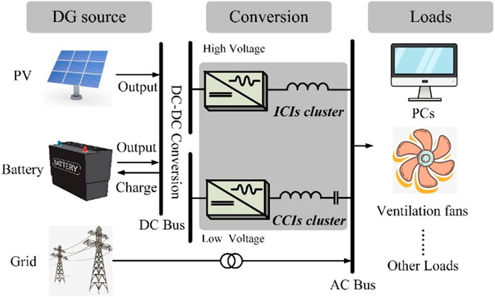
FIGURE 1. Architecture of the proposed parallel-connected ICI-CCI structure.
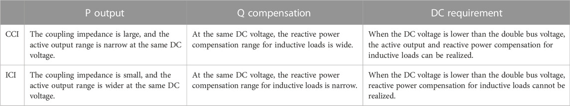
TABLE 1. Comparison of different inverters.
For the proposed MG system, coordinative operation of the inverters is required to regulate the DG output according to changes in load demand (Yazdani et al., 2020). Power-sharing control plays a pivotal role in the inverter’s coordinative operation, and this was investigated by (Mousazadeh Mousavi et al., 2018; Qi et al., 2020). Droop control is simple and widely used since it can regulate inverters locally and achieve power sharing automatically. However, the controller characteristics were easily affected by mismatched feeder impedance, unbalanced loads, and other factors (Mousazadeh Mousavi et al., 2018; Liu et al., 2019b; Razi et al., 2020). For this reason, modified droop control strategies were proposed. To compensate for differences in feeder impedance, a virtual-impedance was devised (Mousazadeh Mousavi et al., 2018)- (Razi et al., 2020). Using specifically designed parameters, the virtual-impedance could also tune the resistive and capacitive feeder impedances and maintain satisfactory power-sharing (Liu et al., 2019b)- (He et al., 2019). Furthermore, by revising the control algorithm, droop control could be enhanced to compensate for inaccurate power-sharing (Lao et al., 2019).
The modified controllers are only for the ICI, and are inappropriate for the proposed MG system. This is first because of the differences in DC-link voltage, which means that the power transfer range was not the same for the CCI and ICI, and the targeted power may surpass the control range of the CCI or the ICI with conventional equal power-sharing control. Secondly, the equal power-sharing ratio was not optimized for inverter total power reduction. For these reasons, a neural network (NN)-based adaptive power sharing scheme was proposed in order to calculate the optimal power-sharing ratio and maintain minimum power capacity. The main contributions of this work include:
• Proposal of a new hybrid system of parallel-connected ICIs and CCIs for better power control flexibility of a microgrid.
• Investigation of the effect of power-sharing ratio on the inverters’ power capacity reduction and its arithmetic computation methods.
• Proposal of a power-sharing controller based on an artificial neural network (NN), to achieve fast, accurate, adaptive power-sharing.
• The principles underlying the NN model applied to the proposed method were studied and evaluated.
This paper is organized as follows. Section 2 introduces the power delivery characteristics of ICIs and CCIs. In Section 3, power flow equations are provided and we investigate how different power sharing ratios affect the proposed MG system’s performance. Section 4 presents the power-ratio restraints and computations based on minimum system cost. A power sharing controller based on an artificial neural network model is also presented in this section. The results of simulations and experiments are given in Section 5 to verify the effectiveness of the proposed control method. The conclusions and implications for adoption are presented in Section 6.
2 Hybrid connected inverters in the MG
2.1 Modelling of the hybrid connected inverters
The equivalent circuit of the hybrid connected inverters is shown in Figure 2. ICI-based and CCI-based DG units are coupled to the power grid with different DC sources. The general power flow from the DG unit to the power grid can be expressed as:
where
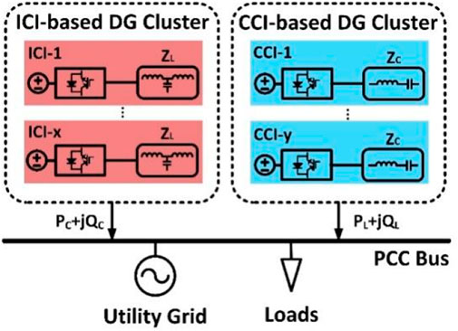
FIGURE 2. Equivalent circuit of hybrid connected inverters in a microgrid system.
To generalize the power flow, a power base is defined as:
By standardizing all ICIs as one ICI unit and all CCIs as one CCI unit, the power output of the inverters in Figure 2 can be expressed as:
2.2 Power control range
Usually, there are three factors that affect the power control range of the inverter: the property of the coupling impedance (inductive or capacitive), the output voltage, and the equivalent value of the coupling impedance. The following discussion focuses on these three aspects in describing the advantages of the proposed MG system. Since the output voltage is proportional to the DC-link voltage, these two voltages are not distinguished in the following discussion.
The main difference between ICI and CCI is the property of the coupling impedance, which leads to different power delivery characteristics. Assuming the direction of active power injection and reactive power compensation is positive, the power base and the DC-link voltage of the ICI and CCI are the same, and the last term is >
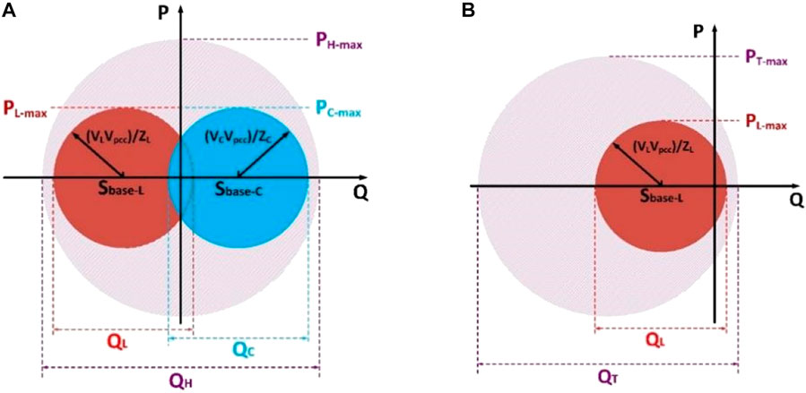
FIGURE 3. Possible power range boundaries with different structures (when the equivalent coupling impedance and the DC voltage of CCI and ICI are the same). (A) Hybrid-connected ICI and CCI. (B) Parallel-connected ICIs.
In Figure 3,
According to Figure 3, it can be found, that with the proposed system, the active power transfer range of the two MG systems is the same, and the reactive power compensation range of the proposed system is much larger than the traditional one.
The output voltage of the inverter will also affect the power transfer. Figure 4 shows the power range with the variation of the output voltage of ICI and CCI.
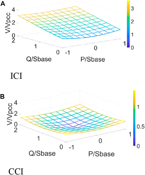
FIGURE 4. Variation in output voltage with power delivery of ICI and CCI. (A) ICI. (B) CCI.
The CCI achieved a wide range of reactive power compensation with lower output voltage, and the DC-link voltage requirement of CCI could be effectively reduced, which increased the adaptiveness and flexibility of the MG system in reactive power compensation (Figure 4).
The equivalent value concept of the coupling impedance can be replaced by the power base. Practically, the power base of the CCI is usually set equal to the nominal load demand of the MG. In this paper, the CCI’s power base is set as a reference like the following:
The ratio of the ICI power base to the reference power base was set as:
If the battery charging in a MG is not considered, the power range boundaries of the proposed MG system can be deduced (Table 2).
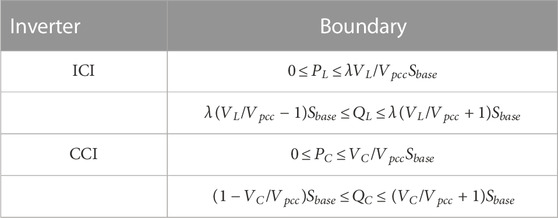
TABLE 2. Power boundary of the hybrid MG system.
To sum up, we believe that the proposed hybrid of ICIs and CCIs connected to a MG system is able to achieve a wider reactive power compensation range. Since the CCI is able to work under a lower DC-link voltage, an optimal power sharing method could reduce the total power capacity compared with a traditional microgrid using ICIs only.
3 Power-sharing for the proposed MG system
3.1 Power sharing ratio
The power-sharing ratio was defined for the proposed MG system. The power reference of the hybrid-connected ICI and CCI can be described as:
where
To normalize the power demands, power reference coefficients are defined as:
The power capacity of ICI and CCI can be deduced as:
where
According to Eq. 9 and Eq. 10, the power capacity of an inverter changes with the power ratio for a given set of active and reactive power references. A detailed discussion will be provided hereinafter.
3.2 Effect of power sharing ratio on power capacity
To better evaluate the effect of power sharing ratio on power capacity, a case study is essential.
Assuming that the power base of the ICI was 1/8 times that of the CCI and the ratio of DC-link voltage to PCC voltage for the ICI was 1.5 and for the CCI, 0.7, six cases with random power reference coefficients are listed in Table 3.
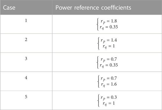
TABLE 3. Power reference coefficients in the case studies.
The positions of the case studies in terms of the power delivery range of the CCI are shown in Figure 5. As shown in the figure, the active power reference in case 1 was much larger than the reactive power reference. In cases 2, 3, and 4, there was little difference between the active and reactive power references, which were uniformly distributed outside the CCI’s power output range. The power references in case 5 both fell within CCI’s power range. To keep the proposed system always working within the minimum power capacity, after receiving the power demand signals, the current from the CCI should be as large as possible because of the lower DC-link voltage, and to keep minimum power capacity the current from the CCI must obey the relationship:
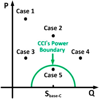
FIGURE 5. Locations of power references in the case study.
By substituting the power reference coefficients into (Eq. 11), we noted that the current from the ICI varied according to the different power-sharing ratios (Figure 6). Thus, the power sharing ratios significantly affected the output current.
FIGURE 6. Total power capacity varies with different power ratios.
According to Figure 6, the lowest point is always located at (0, 0) in the x-y plane, which means the ICI should never output any current on mathematical calculation. However, due to the limitation of voltage and the power base, a single CCI may not always satisfy the power demands. Therefore, to find the correct power sharing ratio to meet the power demands and reduce the ICI current to the lowest possible, a power sharing ratio calculation method is proposed in the next part.
4 Adaptive power sharing method
From the above discussion, we concluded that the power sharing ratio critically affected the total power capacity. Thus, determining the optimal power sharing ratio for the lowest power capacity in the proposed MG is important. In this section, we investigated the power sharing ratio calculation for the unequal power sharing method.
4.1 Power sharing ratio restraints
Power capacity is seriously restricted by the inverter’s output voltage and PCC voltage. Eq. 11 described the relationship between voltage and power, as well as power references as:
The power sharing ratio boundary is also obtained as:
4.2 Power sharing ratio calculation
In the hybrid MG system, the output current of the ICI should be as small as possible because of its higher DC-link voltage. This calculation is expressed as:
Since only the CCI is active in case 5, power sharing is not available. The current vector graphs for power-sharing are illustrated in Figure 7 for cases 1–4.
FIGURE 7. Graph of current vectors in different cases.
In the figure,
For this case study, the number of ICIs under equal power sharing was assumed to be 2.
In Figure 7,
where
The radius of the circle of the CCI’s power range can be described as:
The initial point and the location of the power reference are marked as
and
Assuming the acute angle between
1. When
The power-sharing ratio is:
and:
2. When
The power-sharing ratio is:
and:
3, When
the expression for
and the power-sharing ratio is:
• If the power references satisfy:
the power-sharing ratio is:
4.3 Effectiveness of the adaptive power sharing method
According to Eqs 14–30, the power sharing ratios can be obtained for cases 1–4. The power sharing ratio in case 5 is determined as (0, 0). Thus, the corresponding power ratios under the proposed method and the conventional method were calculated and are summarized in Table 4. As the comparison shows, the proposed power sharing method for the hybrid MG system can effectively reduce the power capacity.
TABLE 4. Summary and comparison of power capacities of different systems.
5 Realization of the NN-based power sharing controller
In the last section, a complete power sharing calculation process is provided. It can be seen that the calculation process is complicated and includes some complex forms of computation, such as trigonometric functions and square roots. It could be difficult for the controller chip to compute when the load demands vary rapidly. To solve this problem, an NN-based power sharing model is proposed in this work.
5.1 Training and evaluation of the NN model
The architecture of an NN model is based on neurons and can be divided into three main parts: the input layer, the hidden layer, and the output layer (Wang et al., 2020). The input layer receives signals from the outside world. The hidden layer is the intermediate layer connecting the input layer and the output layer, and constitutes the core of the NN as being composed of many neurons. The output layer returns the results of the mathematical operations on the input (Liu et al., 2021).
As a representative of a NN the application areas of a back-propagation neural network (BPNN) include function approximation, regression analysis, numerical prediction, and classification and data processing (Chen et al., 2020). The BPNN calculates the final network error based on the forward operation of the input data, transmits the error in the opposite direction, and contains a mechanism for adjusting the weights and thresholds of the corresponding layers according to certain rules when crossing different layers. After a large number of data samples are trained, an algorithmic model that can accomplish complex nonlinear mapping is finally constructed. For such networks, the input layer is responsible for feeding data into the neural network. The hidden layer fits and optimizes the parameters to the neural network by model training. These include weights and biases as well as the selection of various parameters and activation functions. The output layer is responsible for outputting the computational results from the neural network (Wang et al., 2022). The principal algorithm process of the BPNN model in this paper is illustrated in Figure 8.
FIGURE 8. Principal process diagram of the BP neural network algorithm.
The BPNN model can be expressed mathematically as
A loss function was set to examine the difference between the predicted value and the known answer, and also to evaluate the accuracy of the trained NN model. With enough training sessions, the loss function will be stable in the vicinity of a very small value, which can be regarded as the prediction error of the NN model (Huang et al., 2021). In this paper, the sigmoid function was chosen as the activation function and the mean square error (MSE) as the loss function to describe the prediction error.
5.2 Effect of the prediction error
For a BPNN, the number of neurons, hidden layers, as well as training sessions, have a high positive correlation with the final MSE. However, an excessive number of neurons and hidden layers will increase the computational power required of the chip in the power sharing controller. In addition, an increase in the amount of training data will also increase the difficulty of BPNN training (Huang et al., 2021). Therefore, it is essential to choose the proper numbers of neurons and hidden layers, and also the amount of training data. The selection principle is based on experience, as well as the required prediction error of the BPNN.
To evaluate the impact on the total power capacity due to the prediction error, a partial derivative equation is presented. Assuming that the prediction error of the total power capacity is defined as:
there are:
and:
The results from inserting the parameters from cases 1 to 5 into (Eq. 26) are summarized in Table 5.
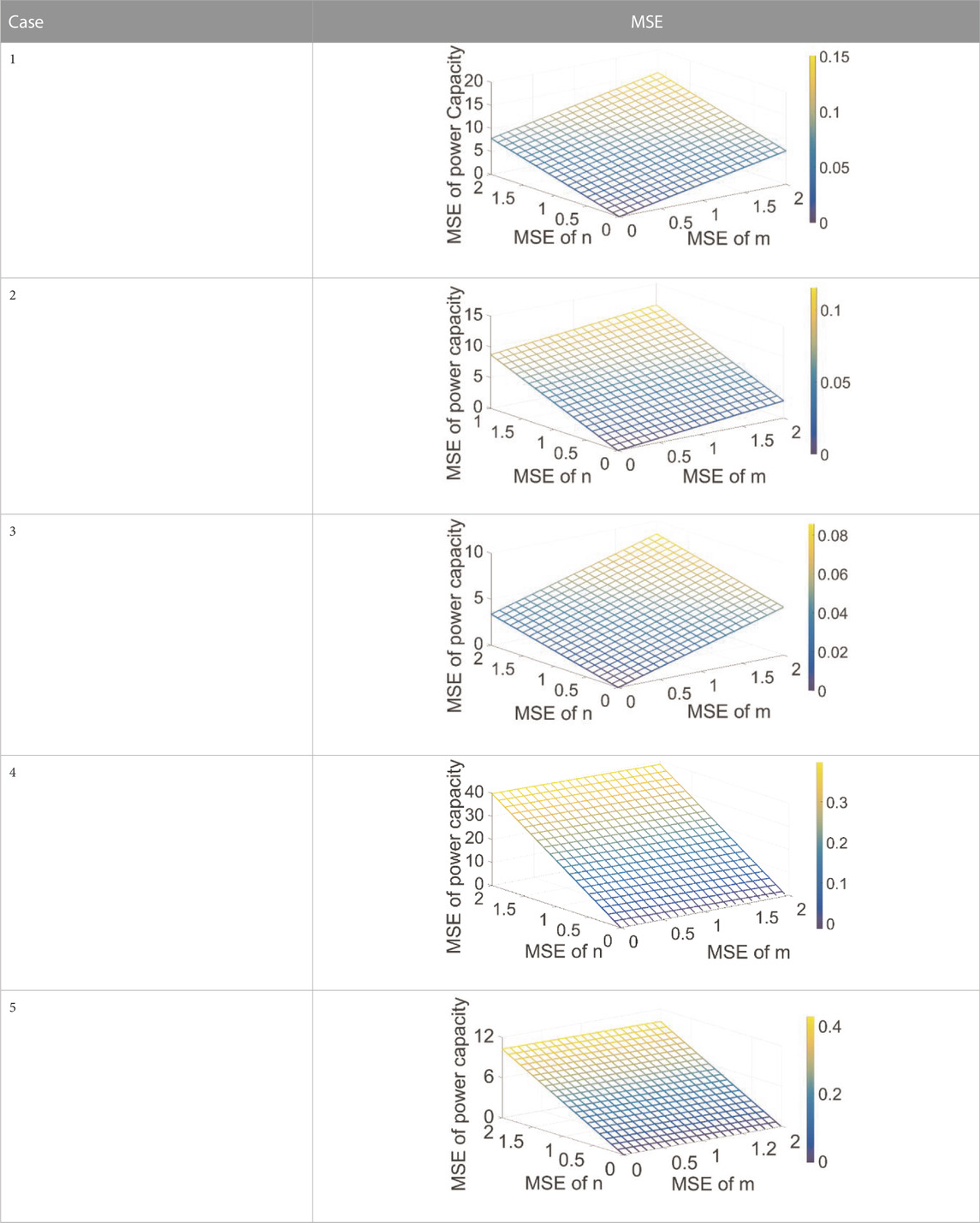
TABLE 5. Partial equation calculation results.
As in Table 4, the degrees of impact of m and n on the total power capacity are not the same. As the reactive power sharing ratio will more critically affect the prediction error, a larger active power demand will increase the effect of the reactive power sharing ratio error on the power capacity. A smaller reactive power output will reduce the influence of the active power sharing ratio on the power capacity.
Assuming that the total power capacity bias should not exceed 5%, the prediction errors of the active and reactive power sharing ratio must be smaller than 0.5%, which means that the MSE of the BPNN cannot be larger than 0.005 to keep the total power bias within a satisfactory range.
The BPNN model includes two hidden layers, and a total of 15 neurons were proposed. The size of the training set was 380 groups of power references and sharing ratios. Like the training results shown in Figure 9, after training, the MSE of the BPNN model reached a value on the order of 10–5, which is satisfactory for generating power sharing ratios.
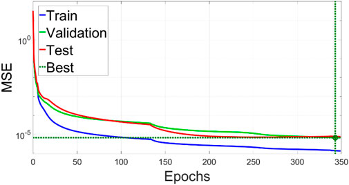
FIGURE 9. Training results of the proposed BPNN.
The control block diagram of the proposed power sharing method for the hybrid ICI and CCI system microgrid is presented in Figure 10. As the figure shows, the power demands will be sent to the secondary power sharing layer with a well-trained BPNN model and generate an optimal power sharing ratio, which can reduce the total power capacity requirement of the hybrid MG system to the minimum value. The power sharing ratio then will be used to calculate the actual power references for the local inverters. Virtual-impedance loops are employed in the local control layers to eliminate the tracking errors by droop control.
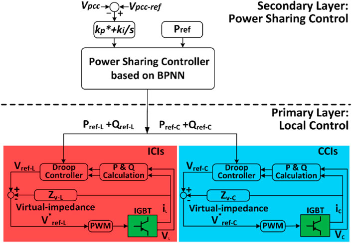
FIGURE 10. Control block diagram of the proposed control method.
6 Simulations and experimental verification
The proposed power sharing method aims to keep the hybrid MG system working with the lowest power capacity and to ensure accurate power transfer. Since the power capacity cannot be obtained by the results of the test, therefore, in this section, all tests will follow the case study strictly, and the results will verify the accuracy of power transfer under the proposed power sharing method.
6.1 Simulation results
Simulation tests were conducted in Matlab/Simulink, to verify the effectiveness of the proposed power sharing strategy. Test cases are listed in Table 3, and the control block diagram is given in Figure 10. Simulation parameters are listed in Table 6. All tests were performed with ICIs under equal power sharing and using the proposed adaptive power sharing model. The simulation results with the proposed MG system and adaptive power sharing method are illustrated in Figure 11 and the results of equal power sharing with the ICIs in the MG system are shown in Figure 12. Power references for each inverter were calculated based on the total power references and power sharing ratio; the references were varied by 1.5 s in each case. Based on the results, the power sharing algorithm proved effective and the output power tracked the reference smoothly and accurately.
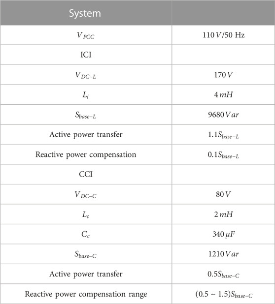
TABLE 6. Summary and comparison of power capacities of different systems.
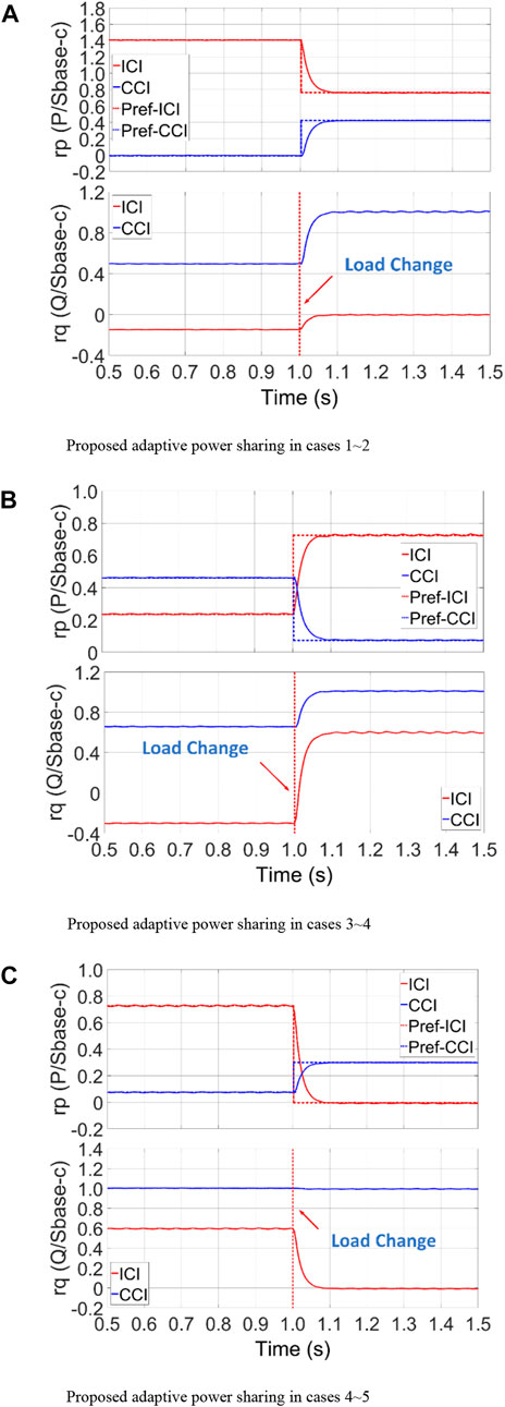
FIGURE 11. Simulation results with the proposed adaptive power sharing in (A) cases 1 and 2, (B) cases 3 and 4, and (C) cases 4 and 5.
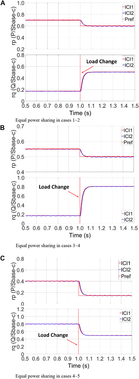
FIGURE 12. Simulation results in the equal power sharing in (A) cases 1 and 2, (B) cases 3 and 4, and (C) cases 4 and 5.
6.2 Experiment verification
To verify the power control effectiveness of the proposed method on the hardware level, a prototype was implemented in the lab (Figure 13). The configuration of the testing system was the same as the simulation. The parallel-connected inverters were controlled by a DSP-based controller. All tests followed the simulation settings. The power transfer waveforms under the different cases are shown in Figure 14.

FIGURE 13. Experimental platform.
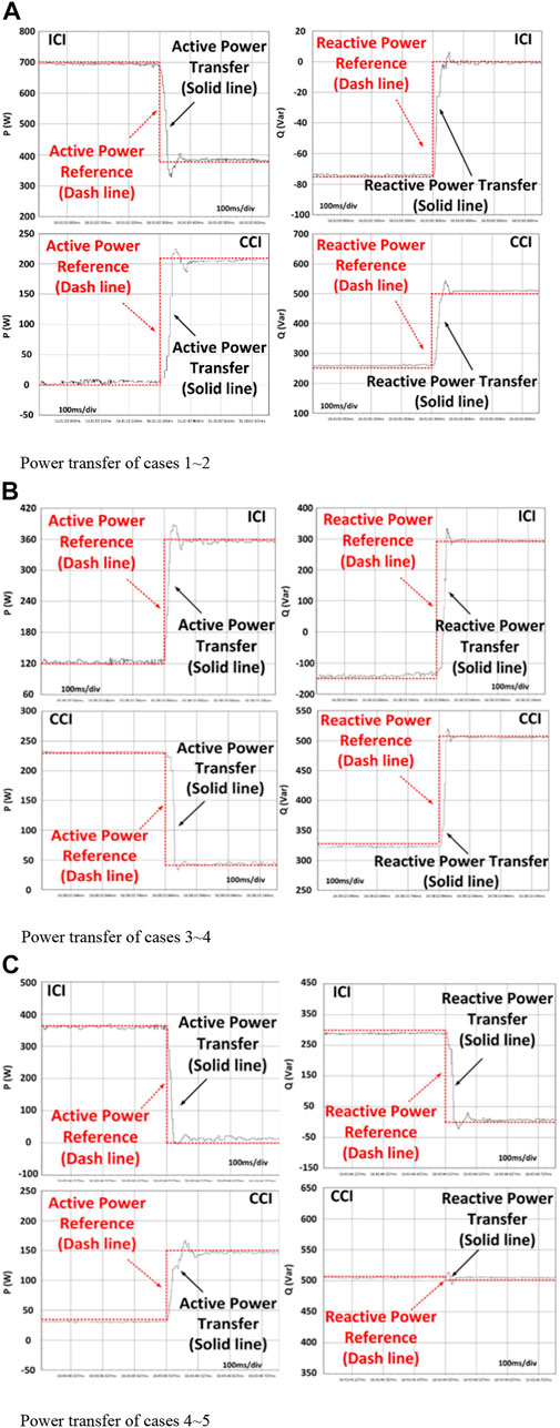
FIGURE 14. Power transfer waveforms under the proposed power sharing. (A) Power transfer of cases 1 and 2. (B) Power transfer of cases 3 and 4. (C) Power transfer of cases 4 and 5.
Similarly, the conventional equal power sharing method was also tested on parallel-connected ICIs. The power transfer waveforms are provided in Figure 15.
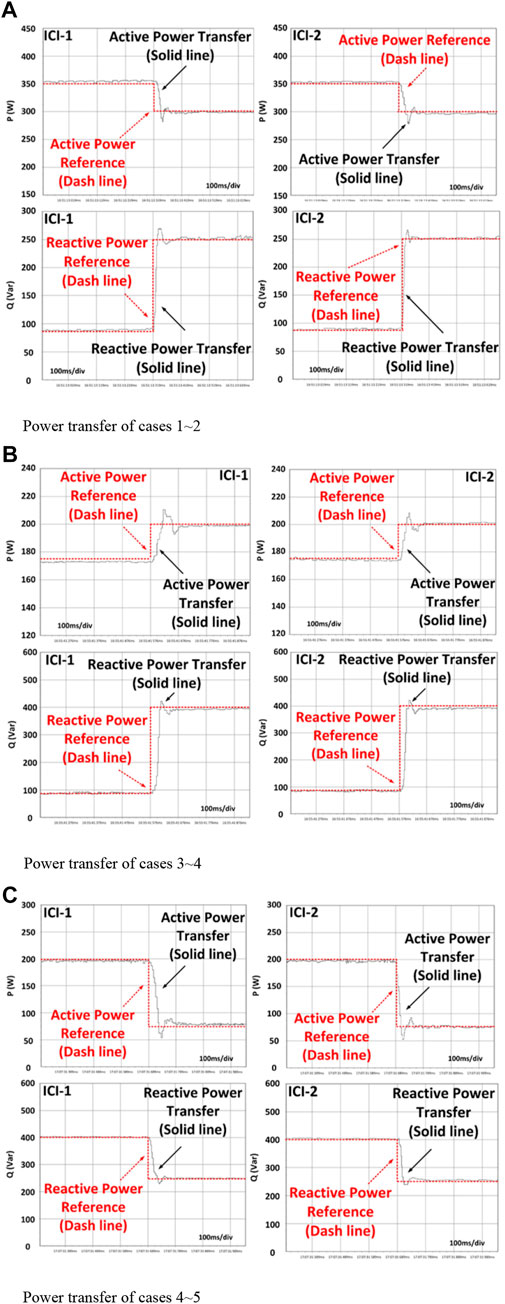
FIGURE 15. Power transfer waveforms under equal power sharing. (A) Power transfer of cases 1 and 2. (B) Power transfer of cases 3 and 4. (C) Power transfer of cases 4 and 5.
7 Conclusion
The CCIs and ICIs have advantages in active and reactive power transfer, respectively. To enhance the reactive power compensation capacity, lower the total power capacity, and reduce transmission losses in a MG system, a hybrid of ICIs and CCIs grid-tied to the MG system was proposed. With its different power characteristics, the conventional equal-sharing method was not suitable for the proposed system. In order to keep the MG system operating continually at minimum power capacity, a power-sharing ratio calculation method for adaptive power sharing was proposed. Simulations and experimental results proved that the hybrid MG system can work well with the proposed control strategy.
Data availability statement
The original contributions presented in the study are included in the article/Supplementary Material; further inquiries can be directed to the corresponding author.
Author contributions
WD and YT provided the ideas and theory of the paper, QL and YY helped to implement the experimental platform, and YZ supervised the research work.
Funding
This work was funded by the China Postdoctoral Science Foundation (2020M682704).
Conflict of interest
The authors declare that the research was conducted in the absence of any commercial or financial relationships that could be construed as a potential conflict of interest.
Publisher’s note
All claims expressed in this article are solely those of the authors and do not necessarily represent those of their affiliated organizations, or those of the publisher, the editors and the reviewers. Any product that may be evaluated in this article, or claim that may be made by its manufacturer, is not guaranteed or endorsed by the publisher.
References
Ahmed, K., Seyedmahmoudian, M., Mekhilef, S., Mubarak, N. M., and Stojcevski, A. (2021). A review on primary and secondary controls of inverter-interfaced microgrid. J. Mod. Power Syst. Clean Energy 9 (5), 969–985. doi:10.35833/mpce.2020.000068
Chen, L., Zhang, F., and Sun, L. (2020). Research on the calibration of binocular camera based on BP neural network optimized by improved genetic simulated annealing algorithm. IEEE Access 8, 103815–103832. doi:10.1109/access.2020.2992652
Deng, W., Dai, N., Lao, K. -W., and Guerrero, J. M. (2020). A virtual-impedance droop control for accurate active power control and reactive power sharing using capacitive-coupling inverters. IEEE Trans. Ind. Appl. 56 (6), 6722–6733. doi:10.1109/tia.2020.3012934Nov.-Dec.
Deng, W., Dai, N. Y., Lao, K., and Guerrero, J. M. “An enhanced power decoupling control for grid-connected capacitive-coupling inverters,” in 2019 IEEE Energy Conversion Congress and Exposition (ECCE), Baltimore, MD, USA, September, 2019, 1466–1473.
Deng, W., Li, Q., Zhang, Y., Yi, Y., and Huang, G. “An unequal power sharing strategy for capacitive- and inductive-coupling inverters in microgrid,” in 2021 IEEE Energy Conversion Congress and Exposition (ECCE), Vancouver, BC, Canada, October, 2021, 3444–3451.
Fujita, H., and Akagi, H. (1991). A practical approach to harmonic compensation in power systems—series connection of passive and active filters. IEEE Trans. Ind. Appl. 27 (6), 1020–1025. doi:10.1109/28.108451Nov.-Dec.
Gong, C., Sou, W.-K., and Lam, C.-S. (2021). Design and analysis of vector proportional–integral current controller for LC-coupling hybrid active power filter with minimum DC-link voltage. IEEE Trans. Power Electron. 36 (8), 9041–9056. doi:10.1109/tpel.2021.3049834Aug
He, J., Du, L., Liang, B., Li, Y., and Wang, C. (2019). A coupled virtual impedance for parallel ac/dc converter-based power electronics system. IEEE Trans. Smart Grid 10 (3), 3387–3400. doi:10.1109/tsg.2018.2825383
Huang, A., Cao, Z., Wang, C., Wen, J., Lu, F., and Xu, L. (2021). An FPGA-based on-chip neural network for TDLAS tomography in dynamic flames. IEEE Trans. Instrum. Meas. 70, 1–11. doi:10.1109/tim.2021.3115210Art no. 4506911
Lao, K., Deng, W., Sheng, J., and Dai, N. (2019). PQ-coupling strategy for droop control in grid-connected capacitive-coupled inverter. IEEE Access 7, 31663–31671. doi:10.1109/access.2019.2902314
Liu, B., Liu, Z., Liu, J., An, R., Zheng, H., and Shi, Y. (2019). An adaptive virtual impedance control scheme based on small-AC-signal injection for unbalanced and harmonic power sharing in islanded microgrids. IEEE Trans. Power Electron. 34 (12), 12333–12355. doi:10.1109/tpel.2019.2905588Dec
Liu, J., Huang, J., Sun, R., Yu, H., and Xiao, R. (2021). Data fusion for multi-source sensors using GA-PSO-BP neural network. IEEE Trans. Intell. Transp. Syst. 22 (10), 6583–6598. doi:10.1109/tits.2020.3010296Oct
Liu, P., Cai, Z., Xie, P., Li, X., and Zhang, Y. (2019). A decomposition coordination planning method for flexible generation resources in isolated microgrids. IEEE Access 7, 76720–76730. doi:10.1109/access.2019.2922756
Mousazadeh Mousavi, S. Y., Jalilian, A., Savaghebi, M., and Guerrero, J. M. (2018). Autonomous control of current- and voltage-controlled DG interface inverters for reactive power sharing and harmonics compensation in islanded microgrids. IEEE Trans. Power Electron. 33 (11), 9375–9386. doi:10.1109/tpel.2018.2792780Nov
Murty, V., and Kumar, A. (2022). Multi-objective energy management in microgrids with hybrid energy sources and battery energy storage systems. Prot. Control Mod. Power Syst. 5 (6), 1–20.
Pang, Y., Xiang, Z., Bai, Z., Wang, L., Wong, C. K., Lam, C. S., et al. (2022). A fusion topology of higher efficiency and lower capacity hybrid parallel multi-converters for power quality compensation. IEEE Trans. Power Electron. 37 (5), 5957–5969. doi:10.1109/tpel.2021.3131747
Qi, Y., Tang, Y., Potti, K. R. R., and Rajashekara, K. (2020). Robust power sharing control for parallel three-phase inverters against voltage measurement errors. IEEE Trans. Power Electron. 35 (12), 13590–13601. doi:10.1109/tpel.2020.2993290Dec
Razi, R., Iman-Eini, H., and Hamzeh, M. (2020). An impedance-power droop method for accurate power sharing in islanded resistive microgrids. IEEE J. Emerg. Sel. Top. Power Electron. 8 (4), 3763–3771. doi:10.1109/jestpe.2019.2926319Dec
Sou, W.-K., Chao, C.-W., Gong, C., Lam, C.-S., and Wong, C.-K. (2022). Analysis design and implementation of multi-quasi-proportional-resonant controller for thyristor-controlled LC-coupling hybrid active power filter (TCLC-HAPF). IEEE Trans. Ind. Electron. 69 (1), 29–40. doi:10.1109/tie.2021.3050393
Wang, S., Zhu, H., Wu, M., and Zhang, W. (2020). Active disturbance rejection decoupling control for three-degree-of- freedom six-Pole active magnetic bearing based on BP neural network. IEEE Trans. Appl. Supercond. 30 (4), 1–5. doi:10.1109/tasc.2020.2990794Art no. 3603505
Wang, W., Zhu, Q., Wang, Z., Zhao, X., and Yang, Y. (2022). Research on indoor positioning algorithm based on SAGA-BP neural network. IEEE Sens. J. 22 (4), 3736–3744. doi:10.1109/jsen.2021.312088215 Feb.15
Yazdani, S., Ferdowsi, M., Davari, M., and Shamsi, P. (2020). Advanced current-limiting and power-sharing control in a PV-based grid-forming inverter under unbalanced grid conditions. IEEE J. Emerg. Sel. Top. Power Electron. 8 (2), 1084–1096. doi:10.1109/jestpe.2019.2959006
Zhang, J., Li, L., Dorrell, D. G., Norambuena, M., and Rodriguez, J. (2019). Predictive voltage control of direct matrix converters with improved output voltage for renewable distributed generation. IEEE J. Emerg. Sel. Top. Power Electron. 7 (1), 296–308. doi:10.1109/jestpe.2018.2874275
Keywords: microgrid, capacitive-coupling inverter, unequal power sharing, power capacity, BPNN
Citation: Deng W, Zhang Y, Tang Y, Li Q and Yi Y (2023) A neural network-based adaptive power-sharing strategy for hybrid frame inverters in a microgrid. Front. Energy Res. 10:1082948. doi: 10.3389/fenrg.2022.1082948
Received: 28 October 2022; Accepted: 21 November 2022;
Published: 06 January 2023.
Edited by:
Xue Lyu, University of Wisconsin-Madison, United StatesCopyright © 2023 Deng, Zhang, Tang, Li and Yi. This is an open-access article distributed under the terms of the Creative Commons Attribution License (CC BY). The use, distribution or reproduction in other forums is permitted, provided the original author(s) and the copyright owner(s) are credited and that the original publication in this journal is cited, in accordance with accepted academic practice. No use, distribution or reproduction is permitted which does not comply with these terms.
*Correspondence: Yuan Tang, dGFuZ3l1YW5Ac2N1dC5lZHUuY24=