 Salam J. Yaqoob1*
 Husam Arnoos2
 Mohammed A. Qasim3,4
 Ephraim B. Agyekum3
 Ahmad Alzahrani5*
 Salah Kamel6,7*
- 1Department of Research and Education, Authority of the Popular Crowd, Baghdad, Iraq
- 2Department of Control and Communication, The Ministry of Electricity, Baghdad, Iraq
- 3Nuclear Power Plants and Renewable Energy Sources Department, Ural Federal University, Yekaterinburg, Russia
- 4Department of Projects and Engineering Services, Ministry of Health, Baghdad, Iraq
- 5Electrical Engineering Department, College of Engineering, Najran University, Najran, Saudi Arabia
- 6Electrical Engineering Department, Faculty of Engineering, Aswan University, Aswan, Egypt
- 7Applied Science Research Center, Applied Science Private University, Amman, Jordan
The purpose of this paper is to propose an energy management strategy (EMS) based on flatness control method for a standalone hybrid photovoltaic-battery system. The goal of the proposed method is to use non-linear flatness theory to develop an efficient EMS in order to provide a stable DC bus voltage and an optimal power sharing process between the solar array and the battery. The suggested EMS is responsible for balancing the power reference for the PV system and the battery while keeping the DC bus voltage steady and performing at its reference value. In order to maximize the PV’s power, a perturb and observe with a variable step size (VSSP and P&O) based maximum power point tracking (MPPT) method with a DC/DC boost converter was used. In addition, a DC/DC bidirectional converter was developed to control the charging and discharging process of the battery. Moreover, the proposed EMS strategy was verified in a MATLAB®/Simulink-based simulation environment by subjecting it to a variety of scenarios, including those with varying degrees of irradiation and sudden changes in load. The obtained results show that the presented EMS method was able to keep the bus voltage stable despite changes in load or solar radiation. Furthermore, the EMS By minimizing bus voltage spikes, the technique also ensured excellent power quality which helped the battery’s operation in terms of lifetime and efficiency. Finally, the suggested strategy has a minimum overshoot rate in the bus voltage and higher tracking efficiency compared with the classical load following (LF) strategy under various load conditions.
1 Introduction
1.1 Background and motivation
Microgrid (MG) operation with distributed generation units (DG) and renewable energy sources (RES), such as photovoltaic (PV) systems, wind turbine (WT), and proton exchange membrane (PEM) fuel cells (FC), is now the most commonly used in electrical power systems (Evans et al., 2009; Qazi et al., 2019; Sinsel et al., 2020). In addition, the use of these sources necessitates the addition of a supplementary energy storage system unit in order to reduce power fluctuations and increase the availability of electricity (Molina and Juanico, 2010). In contrast, stand-alone or off-grid photovoltaic (PV) systems using Li-ion batteries that are more efficient have gained popularity in recent years (Vonsien and Madlener, 2020). It is essential in that system to have an EMS between the photovoltaic cells, the battery, and the load in order to transfer the right amount of power between the sources and increase the lifespan of the battery (Rydh and Sandén, 2005; Bragard et al., 2010; Campana et al., 2021). In point of fact, it is possible to achieve the maximum power of the PV system by using a maximum power point tracking (MPPT) device. This device not only improves the effectiveness of the PV systems but also improves their performance in a variety of weather conditions (Saleh et al., 2020; Yaqoob et al., 2020). In order to manage the duty cycle and extract the peak power, an MPPT device is installed into a PV system or module with an appropriate DC/DC converter. Several other MPPT methods, including perturb and observe (P & O), incremental conductance (IC), fuzzy logic, and several others, are used in the application of PV systems (Rizzo and Scelba, 2015; Robles Algarín et al., 2017; Rezk et al., 2019; Shang et al., 2020). Managing lithium-ion batteries, on the other hand, can improve performance, extend battery life, and cut down on power losses in the grid. The right way to manage the battery may help keep the DC bus voltage constant and improve the way power is shared between the load and the generator (Mesbahi et al., 2017; Hannan et al., 2018; Berrueta et al., 2020).
1.2 Previous works
Off-grid photovoltaic (PV) systems or DCMG systems with battery energy storage systems and renewable energy sources have been proposed by a number of researchers (Shiau et al., 2009; Ongaro et al., 2012; Li et al., 2015). These systems are intended to improve efficiency and deliver optimal power to the load by utilizing power DC/DC converters. For example, the authors of (Fathabadi, 2019) proposed a hybrid power system consisting of solar panels, fuel cells, and batteries that could charge electric vehicles (EVs) that use lithium-ion batteries. The work that was given was modeled and simulated by utilizing the MATLAB® and Simulink software, and the efficiency of the system fulfilled expectations. This was shown by the fact that the generated outputs matched up with the outcomes that were needed. It was also found out that it is feasible to increase the energy efficiency of this system by making use of electrical equipment that is more energy efficient, such as batteries that run on lithium-ion. In a remote location, Khadepaun et al. (Khadepaun and Shah, 2020) presented a demonstration of a hybrid MG that was powered by a solar PV system as well as PEMFC cells. According to the findings of this research, the use of environmentally friendly fuel cells as energy source units in small grid plants is the superior choice to the utilization of lithium batteries, which have a life span of between five and 7 years. When it has reached the end of its useful life, it should be thrown away, which is another way in which it harms the environment. According to the findings of the research, making use of DC loads, such as electric vehicles, lights, and chargers, makes the MG system more efficient and productive since it eliminates losses that would have been generated by shifting current from DC to AC. The power system that Gonzalez et al. (Gonzalez et al., 2019) suggest using is a PV/FC/battery MG system that also includes a battery unit for energy storage. The model predictive control method is used inside an EMS in order to distribute the appropriate amount of real power to the grid. This strategy cuts down on how much power the battery needs, but it depends on how accurate the prediction is, which is a variable and unpredictable factor.
The authors of (Tofighi and Kalantar, 2011) suggested using EMS to manage the power flow between the sources and load for a PV/battery system using linear PI management. This would allow the authors to control the flow of power. MATLAB® and Simulink were used in order to verify the accuracy of the provided technique. The findings that were acquired were achieved under a variety of load situations, and they demonstrate that the suggested PV-battery system has a quick speed response as well as a minimal oscillation in DC voltage. However, in classic EMS, a proportional-integral (PI) control was used to regulate the power sharing between PV, the battery, and the load (Kewat et al., 2018). This type of control has several problems, the most important of which are the need for tuning, the linear control type, and the slow dynamics.
The study in (Sharma et al., 2022) presented a sensitivity analysis and techno-economic modeling of a MG system consisting of solar, wind, hydro, and battery storage, with this MG system linked to the utility grid. One benefit of the on-grid approach for rural areas is that any extra power from RES can be sold back to the utility grid. This helps find the lowest Levelized Cost of Energy (LCOE) and Total Net Present Cost (TNPC). The authors in (Belaid et al., 2022a; Belaid et al., 2022b), proposed a power management control (PMC) based optimization for a wind/battery system. This method is created and coupled to the suggested two-level MPPT controller in order to facilitate the management of the wind and battery power system. The used PMC guarantees that the utilised storage batteries are subjected to the least amount of stress possible by providing efficient optimum functioning of two MPPT algorithms. The primary purpose of the PMC-based system is to meet the power requirements of the load, while secondary goals include preserving the state of charge of the battery bank, avoiding power outages, and maximizing the useful life of the batteries. The authors in (Dashtdar et al., 2022) proposed an EMS for a residential MG system in order to reduce the cost of operating the MG sources. The suggested EMS method is implemented on the combined heat power (CHP) with batteries and the obtained results show the effect of the battery on MG participation in load response. In addition, the cost of operating a MG and how to exchange with the grid under varying market price tariffs are analyzed, with results demonstrating the efficacy of the suggested strategy.
1.3 Research contributions
This article presents an optimum EMS based on the non-linear flatness control theory for an off-grid hybrid solar PV system.
The following are the main contributions that are presented by this research:
1 Suggests a non-linear control based EMS for PV-battery power systems that provides excellent quality for the output power.
2 Manages the Li-ion battery based on its power reference in order to ensure optimal performance and stable voltage at the DC link connection.
3 Proposes a highly efficient VSSP&O based MPPT to optimize the output power of the PV array without power oscillation.
1.4 Research structure
This paper was structured into the following sections: Section 2 introduces photovoltaic system modeling. Section 3 presents the proposed energy management strategy. Section 4 reports the simulation results and discussion. Finally, Section 5 presents the conclusion of the paper.
2 Photovoltaic system modeling
2.1 Model of PV array
Figure 1 depicts the electrical circuit of a PV cell model used in this study (Molina and Juanico, 2010; Saleh et al., 2020). It is simple and straightforward to express in the MATLAB® environment and provides enough representation for the PV array. The PV array current (
where the components in the above equation are summarized as follows:
✓
✓
✓
✓
✓
✓
✓
✓
✓
✓
✓
✓
✓
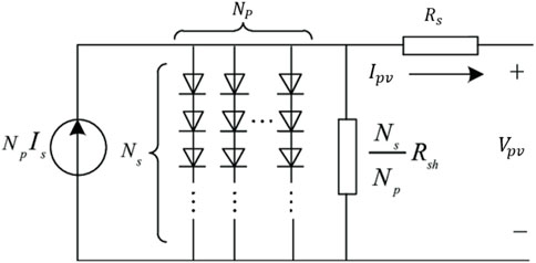
FIGURE 1. Electrical circuit for a single-diode photovoltaic array.
Furthermore, in this research, the PV array employed in simulation is made up of 5 × 10 array, resulting in a large PV array of 10 kW to deliver adequate DC power and voltage to the DC load side and battery. Furthermore, the employed PV array was connected via a DC/DC boost converter to amplify the PV voltage and implement the MPPT algorithm for varied irradiance profiles. Table 1 shows the datasheet parameters of the employed PV module type KC200GT under STC circumstances (Energy Matters, 2020). These parameters include maximum output power
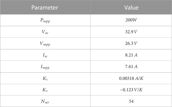
TABLE 1. Datasheet parameters of the KC200GT PV module at STC conditions.
2.2 Suggested MPPT method
A MPPT approach is required in PV system applications to optimize power from the PV system and to increase system performance under varying weather conditions (Rizzo and Scelba, 2015; Yaqoob et al., 2020). Furthermore, the MPPT control is used to create the required duty cycle and to activate the boost circuit’s switch as seen in Figure 2. Several low-cost and easy MPPT approaches, including P&O and IC techniques, were applied to extract the maximum power from the PV module (Saleh et al., 2020; Yaqoob et al., 2020). In this paper, a VSSP&O MPPT was used to track the MPP of the P-V characteristics of the PV system. The flowchart of the presented MPPT method is illustrated in Figure 3. The presented MPPT was designed with a variable step size in order to vary the duty ratio with respect to the change in power. Thus, this method is more efficient than the traditional fixed step size P&O. Therefore, the PV system will be controlled without power oscillation around the MPP, and the performance will be improved.
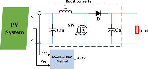
FIGURE 2. Block diagram of the suggested MPPT controller with boots converter.

FIGURE 3. Flowchart of the modified VSSP&O MPPT technique.
2.3 Li-ion battery modeling
Li-ion batteries are extensively used in many power systems due to their increased efficiency when compared to other technologies (Ferahtia et al., 2021). It is known as a lithium-metal battery because it contains metallic lithium as an anode. However, a greater energy density was attained from a battery with a little power density. The increased energy density of the Li-ion battery makes it more appropriate for off-grid PV applications, especially when electricity availability is limited. The battery model utilized in this study is based on the MATLAB/Simulink® model shown in Figure 4. The battery’s output voltage can be stated as follows (Ferahtia et al., 2021):
where the above battery’s parameters can be defined as.
• Vb is the output voltage of the battery (V),
• E0 is the voltage at the open-circuit case
• Q is the normal battery’s capacity (Ah),
• K is the polarization constant,
• it is the current battery charge (
•
• B denotes the exponential zonetime constant inverse in the exponential zone (Ah−1);
• Rb is the internal resistance (Ω), and
• i and i* are the battery current and the filtered current (A), respectively.
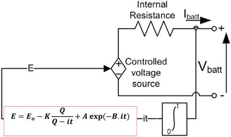
FIGURE 4. Electrical model of li-ion battery.
The battery design was implemented under simulation based on the characteristics listed in Table 2. The battery module parameters are shown in Figure 5. The initial SOC of the battery is 95%. A battery bank of
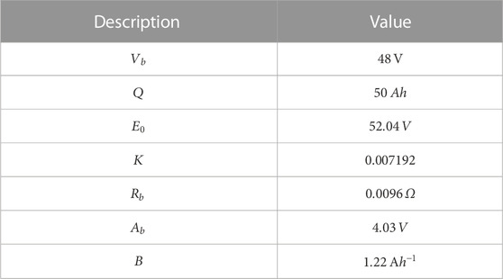
TABLE 2. The battery’s design parameters.
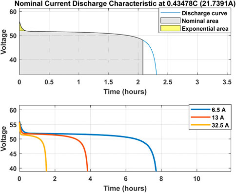
FIGURE 5. The battery characterestics used in this work.
2.4 Desing of boost converter
The electrical boost converter circuit that shown in Figure 2 have three main parameters which are should be calculated to design the boost conveter in the simulation or practical operation. As a result, the following Equations 3-5 are utilized for the inductor current (
where
3 Proposed EMS strategy
Using a PV-Li-ion battery as a hybrid power system, as seen in Figure 6, can improve the performance and meet the load demand. As seen in Figure 1, both a Li-ion battery and a PV system are connected to the DC bus by a DC/DC boost converter and a bidirectional DC/DC converter, respectively, to supply the DC load. In this study, an efficient EMS based on flatness control theory is utilized to estimate the reference power of the battery and supply the DC load demand while maintaining the bus voltage within standard limits
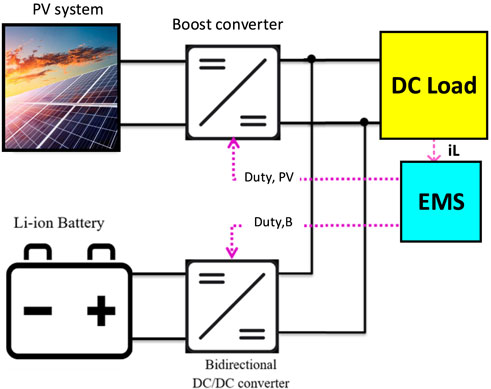
FIGURE 6. The proposed hybrid PV-battery power system.
Because of the system’s non-linearity for the PV-battery system, the control technique may be more complicated. Because of this, the classical linear PI control method was replaced with the differential non-linear flatness theory to reduce the order of the model (Ferahtia et al., 2020):
where the above items can be indicted below:
•
•
•
•
•
• Also,
•
The proposed EMS was applied to the HPS system to estimate the required power from the load and generate the optimal EMS for the battery and the PV system. The proposed model under flatness theory was defined as follows:
where
where
where
Furthermore, both the PV and battery follow their power reference values, which are expressed in Eqs 15, 16. The output power of the PV system was tracked using an MPPT controller, while the power of the battery module was estimated using trajectory planning in flatness control.
Furthermore, the input control unit (
where is the limited maximum power of the battery,
Moreover, the most critical variable in the proposed system is the flat output
From this equation, it is clear that the output transfer function is a pure integrator. So, a PI controller is applied based on the supposing of
where
The block diagram of the proposed EMS is illustrated in Figure 7.
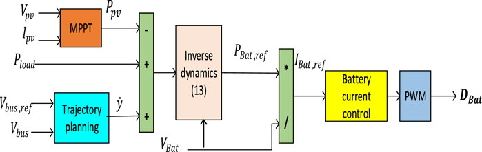
FIGURE 7. Proposed EMS of the hybrid PV-battery model.
4 Simulation results and discussion
Following the design of the control strategy, MATLAB/Simulink®2021 software was used to test and prove the hybrid power system in order to validate the effetiveness of the proposed EMS. Both the PV system and the battery are connected to a shared DC bus via DC/DC converters, and the control system is employed to keep the voltage constant at its reference. The reference voltage for the DC bus is 380V, which is tracked to ensure stability. The parameters of the proposed system are listed in Table 3.
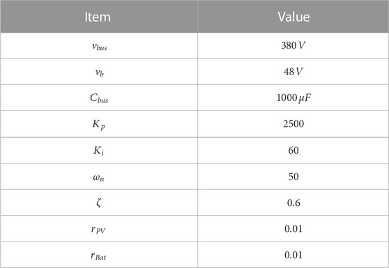
TABLE 3. Simulation parameters of the system.
Moreover, the proposed HPS was tested at different irradiance profiles. To emulate the real irradiance variations, the irradiance profile shown in Figure 8 was utilized to demonstrate the system’s performance. The temperature is assumed to be
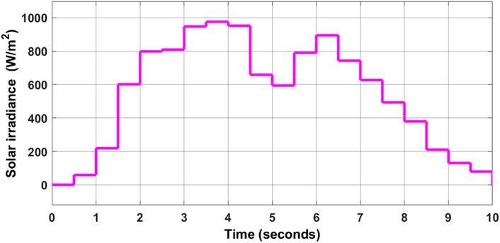
FIGURE 8. The solar irradiance profile used in this study.
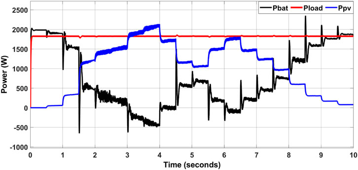
FIGURE 9. Power graphs of the PV system, load, and battery.
The results of the DC bus voltage during 10 s are shown in Figure 10. The first curve which is drawn in red colour represents the DC bus reference voltage, while the second curve in blue represents the measuring DC bus voltage under varying irradiance levels. As a result of this, the DC bus voltage utilizing the proposed EMS can provide improved performance with faster response and less overshoot, as well as more resilience. Furthermore, the DC bus voltage is stabilized, with a maximum overshoot voltage of
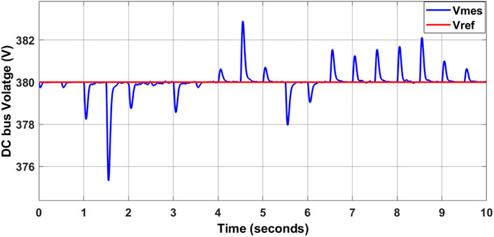
FIGURE 10. Simulation result of DC bus voltage.
The state of charge (SOC) of the battery is illustrated in Figure 11. As seen, this figure explains the behavior of the Li-ion battery. It mainly supplies (discharges) with a decrease in solar irradiance. While it charges (absorbs) with the step-up in irradiance.
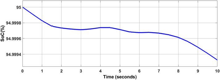
FIGURE 11. SOC of the battery.
To validate the performance of the proposed EMS, the DC load power profile shown in Figure 12 is used. In this case, the output power of the PV system is extracted with constant weather conditions of
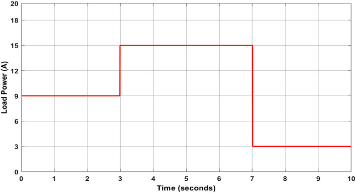
FIGURE 12. The suggested load profile.
Figure 13 reports power curves that were obtained during the simulation. This figure shows the battery power, load power, and PV system power. In the initial simulation, the power of the load is relatively high (
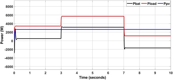
FIGURE 13. Power curves of the PV system, load and battery.
Furthermore, at
At
• The Li-ion battery absorbs the surplus of the bus power with limited power dynamics.
• The PV system supplied the demand power
The proposed EMS successfully controls the voltage of the DC bus, as seen in Figure 14 in the case of different load conditions. This figure demonstrates the effectiveness of the proposed EMS in achieving DC bus voltage stability and minimizing ripple content while maintaining excellent power quality. Figure 15 shows the SOC of the battery in the case of varying load power conditions.
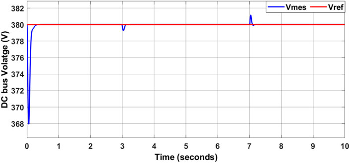
FIGURE 14. Simulation result of DC bus voltage.
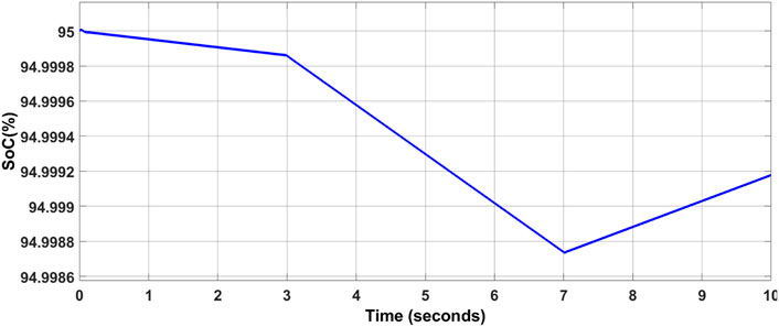
FIGURE 15. SOC of the battery under various values of the load.
In order to include more results with changes in both PV and load at the same time, Figure 16 reports power curves that were obtained for step changes in irradiance and output load. As seen in this figure, in beginning the PV system supplied the demand load while keeping the battery in charging mode according to its SOC. When the power system is subject to a fast change in PV generation and a high transient load, the PV power provides the increase in the load and the excess energy is used to charge the battery. As can be observed in Figure 17, the voltage of the DC bus is successfully controlled by the EMS that has been proposed, even when subjected to a variety of load and irradiance. This figure indicates that the suggested EMS is effective in attaining DC bus voltage stability. Figure 18 illustrates the SOC of the battery under a variety of load power and irradaiton circumstances.
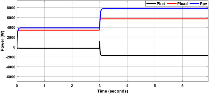
FIGURE 16. Power curves of the PV system, load and battery with changes in both PV and load.
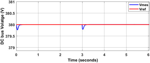
FIGURE 17. The obtained result of the DC bus voltage under various irradiance and load conditions.
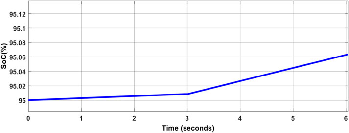
FIGURE 18. SOC of the battery.
To prove the novelty of the suggested EMS, a comparison between the proposed EMS and the conventional load following (LF) based EMS strategy under different load conditions was presented as seen in Table 4. It is clear that the suggested strategy has a minimum overshoot rate in bus voltage and higher tracking efficiency compared with the classical LF strategy.
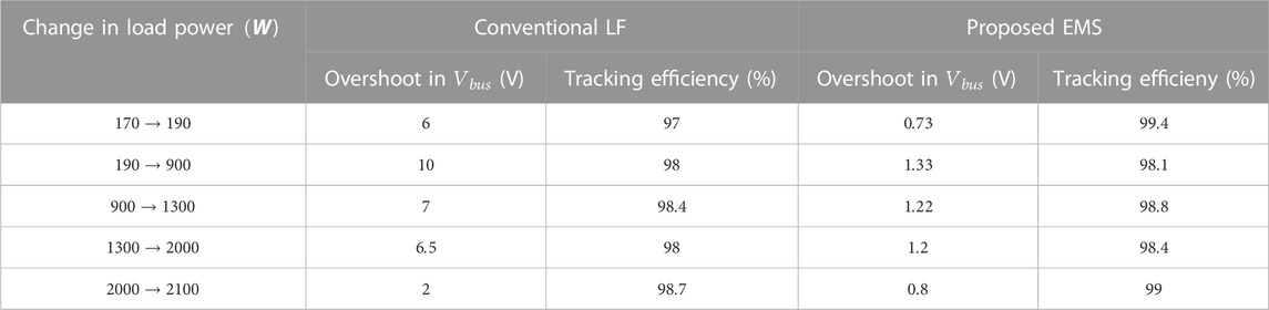
TABLE 4. Comparison between the proposed EMS and the conventional LF method under different load conditions.
In summary, the optimal EMS of the Li-ion battery will extend its lifetime, which is an important issue in a hybrid PV-battery system. Furthermore, stabilizing the DC bus voltage with its reference value allows the system to run at high power quality.
5 Conclusion and future work
In this research, an optimal energy management strategy (EMS) for a hybrid PV-battery system-based on non-linear flatness theory was presented. First, the mathematical analysis with details for both the PV array and Li-ion battery was presented. Second, the non-linear flatness theory was derived and applied to the proposed PV-battery system to estimate the desired power for the PV system and battery. MATLAB/Simulink® was used to model and simulate the proposed EMS. The performance of the proposed system was tested under both irradiance and load power variations. According to the simulation findings, the suggested EMS provides high power quality by stabilizing the values of the DC bus voltage and providing low ripple content in bus voltage
This study recommends the following topics for further research: 1) analysis of the flatness EMS with a new DC MG containing FC, PV, and supercapacitor module; and 2) design and implementation of a new EMS with an online optimization approach-based MG system.
Data availability statement
The original contributions presented in the study are included in the article/supplementary material, further inquiries can be directed to the corresponding authors.
Author contributions
All authors listed have made a substantial, direct, and intellectual contribution to the work and approved it for publication.
Acknowledgments
The authors acknowledge financial support from the Deanship of Scientific Research at Najran University for funding this work under the Research Collaboration Funding program grant code (NU/RC/SERC/11/1).
Conflict of interest
The authors declare that the research was conducted in the absence of any commercial or financial relationships that could be construed as a potential conflict of interest.
Publisher’s note
All claims expressed in this article are solely those of the authors and do not necessarily represent those of their affiliated organizations, or those of the publisher, the editors and the reviewers. Any product that may be evaluated in this article, or claim that may be made by its manufacturer, is not guaranteed or endorsed by the publisher.
References
Belaid, S., Rekioua, D., Oubelaid, A., Ziane, D., and Rekioua, T. (2022). A power management control and optimization of a wind turbine with battery storage system. J. Energy Storage 45, 103613. doi:10.1016/j.est.2021.103613
Belaid, S., Rekioua, D., Oubelaid, A., Ziane, D., and Rekioua, T. (2022). Proposed hybrid power optimization for wind turbine/battery system. Periodica Polytech. Electr. Eng. Comput. Sci. 66 (1), 60–71. doi:10.3311/ppee.18758
Berrueta, A., Soto, A., Marcos, J., de la Parra, Í., Sanchis, P., and Ursúa, A. (2020). Identification of critical parameters for the design of energy management algorithms for li-ion batteries operating in PV power plants. IEEE Trans. Industry Appl. 56 (5), 4670–4678. doi:10.1109/tia.2020.3003562
Bragard, M., Soltau, N., De Doncker, R. W., and Schmiegel, A. (2010). Design and implementation of a 5 kW photovoltaic system with li-ion battery and additional DC-DC converter. in 2010 IEEE Energy Conversion Congress and Exposition. Atlanta, GA, USA, 12-16 September 2010, IEEE, 2944–2949.
Campana, P. E., Cioccolanti, L., François, B., Jurasz, J., Zhang, Y., Varini, M., et al. (2021). Li-Ion batteries for peak shaving, price arbitrage, and photovoltaic self-consumption in commercial buildings: A Monte Carlo analysis. Energy Convers. Manag. 234, 113889. doi:10.1016/j.enconman.2021.113889
Dashtdar, M., Bajaj, M., and Hosseinimoghadam, S. M. S. (2022). Design of optimal energy management system in a residential microgrid based on smart control. Smart Sci. 10 (1), 25–39. doi:10.1080/23080477.2021.1949882
Energy Matters (2020). Kyocera multi-crystal photovoltaic modules. Available at: https://www.energymatters.com.au/images/kyocera/KC200GT.pdf.
Evans, A., Strezov, V., and Evans, T. J. (2009). Assessment of sustainability indicators for renewable energy technologies. Renew. Sustain. energy Rev. 13 (5), 1082–1088. doi:10.1016/j.rser.2008.03.008
Fathabadi, H. (2019). Combining a proton exchange membrane fuel cell (PEMFC) stack with a Li-ion battery to supply the power needs of a hybrid electric vehicle. Renew. energy 130, 714–724. doi:10.1016/j.renene.2018.06.104
Ferahtia, S., Djerioui, A., Zeghlache, S., and Houari, A. (2020). A hybrid power system based on fuel cell, photovoltaic source and supercapacitor. SN Appl. Sci. 2 (5), 940–941. doi:10.1007/s42452-020-2709-0
Ferahtia, S., Djeroui, A., Mesbahi, T., Houari, A., Zeghlache, S., Rezk, H., et al. (2021). Optimal adaptive gain LQR-based energy management strategy for battery–supercapacitor hybrid power system. Energies 14 (6), 1660. doi:10.3390/en14061660
Gonzalez, A. A., Bottarini, M., Vechiu, I., Gautier, L., Ollivier, L., and Larre, L. (2019). Model predictive control for the energy management of A hybrid PV/Battery/Fuel cell power plant. In 2019 International Conference on Smart Energy Systems and Technologies (SEST). Porto, Portugal, 9-11 September 2019, 1–6. IEEE.
Hannan, M. A., Hoque, M. M., Hussain, A., Yusof, Y., and Ker, P. J. (2018). State-of-the-art and energy management system of lithium-ion batteries in electric vehicle applications: Issues and recommendations. Ieee Access 6, 19362–19378. doi:10.1109/access.2018.2817655
Kewat, S., Singh, B., and Hussain, I. (2018). Power management in PV-battery-hydro based stand-alone microgrid. IET Renew. Power Gener. 12 (4), 391–398. doi:10.1049/iet-rpg.2017.0566
Khadepaun, N. C., and Shah, N. (2020). Operation of solar PV with PEM fuel cell for remote hybrid microgrid. In 2020 IEEE International Conference on Electronics, Computing and Communication Technologies (CONECCT). Bangalore, India, 02-04 July 2020, IEEE, 1–6.
Li, Q., Li, N., Ishida, M., and Zhou, H. (2015). Saving electric energy by integrating a photoelectrode into a Li-ion battery. J. Mater. Chem. A 3 (42), 20903–20907. doi:10.1039/c5ta06908d
Mesbahi, T., Rizoug, N., Bartholomeüs, P., Sadoun, R., Khenfri, F., and Le Moigne, P. (2017). Optimal energy management for a li-ion battery/supercapacitor hybrid energy storage system based on a particle swarm optimization incorporating Nelder–Mead simplex approach. IEEE Trans. Intelligent Veh. 2 (2), 99–110. doi:10.1109/TIV.2017.2720464
Molina, M. G., and Juanico, L. E. (2010). Dynamic modelling and control design of advanced photovoltaic solar system for distributed generation applications. J. Electr. Eng. Theory Appl. (JEETA) 1 (3), 141–150. doi:10.5772/7092
Ongaro, F., Saggini, S., and Mattavelli, P. (2012). Li-ion battery-supercapacitor hybrid storage system for a long lifetime, photovoltaic-based wireless sensor network. IEEE Trans. Power Electron. 27 (9), 3944–3952. doi:10.1109/tpel.2012.2189022
Qazi, A., Hussain, F., Rahim, N. A., Hardaker, G., Alghazzawi, D., Shaban, K., et al. (2019). Towards sustainable energy: A systematic review of renewable energy sources, technologies, and public opinions. IEEE Access 7, 63837–63851. doi:10.1109/access.2019.2906402
Rezk, H., Aly, M., Al-Dhaifallah, M., and Shoyama, M. (2019). Design and hardware implementation of new adaptive fuzzy logic-based MPPT control method for photovoltaic applications. Ieee Access 7, 106427–106438. doi:10.1109/access.2019.2932694
Rizzo, S. A., and Scelba, G. (2015). ANN based MPPT method for rapidly variable shading conditions. Appl. Energy 145, 124–132. doi:10.1016/j.apenergy.2015.01.077
Robles Algarín, C., Taborda Giraldo, J., and Rodriguez Alvarez, O. (2017). Fuzzy logic based MPPT controller for a PV system. Energies 10 (12), 2036. doi:10.3390/en10122036
Rydh, C. J., and Sandén, B. A. (2005). Energy analysis of batteries in photovoltaic systems. Part I: Performance and energy requirements. Energy Convers. Manag. 46 (11-12), 1957–1979. doi:10.1016/j.enconman.2004.10.003
Saleh, A. L., Obed, A. A., Hassoun, Z. A., and Yaqoob, S. J. (2020). Modeling and simulation of A low cost perturb& observe and incremental conductance MPPT techniques. in Proteus Software Based on Flyback Converter” In IOP Conference Series: Materials Science and Engineering, 10 August 2020, Iraq: IOP Publishing, 012152.
Shang, L., Guo, H., and Zhu, W. (2020). An improved MPPT control strategy based on incremental conductance algorithm. Prot. Control Mod. Power Syst. 5 (1), 14–18. doi:10.1186/s41601-020-00161-z
Sharma, S., Sood, Y. R., Sharma, N. K., Bajaj, M., Zawbaa, H. M., Turky, R. A., et al. (2022). Modeling and sensitivity analysis of grid-connected hybrid green microgrid system. Ain Shams Eng. J. 13 (4), 101679. doi:10.1016/j.asej.2021.101679
Shiau, J. K., Ma, D. M., Yang, P. Y., Wang, G. F., and Gong, J. H. (2009). Design of a solar power management system for an experimental UAV. IEEE Trans. Aerosp. Electron. Syst. 45 (4), 1350–1360. doi:10.1109/taes.2009.5310303
Sinsel, S. R., Riemke, R. L., and Hoffmann, V. H. (2020). Challenges and solution technologies for the integration of variable renewable energy sources-a review. Renew. Energy 145, 2271–2285. doi:10.1016/j.renene.2019.06.147
Tofighi, A., and Kalantar, M. (2011). Power management of PV/battery hybrid power source via passivity-based control. Renew. Energy 36 (9), 2440–2450. doi:10.1016/j.renene.2011.01.029
Vonsien, S., and Madlener, R. (2020). Li-ion battery storage in private households with PV systems: Analyzing the economic impacts of battery aging and pooling. J. Energy Storage 29, 101407. doi:10.1016/j.est.2020.101407
Yaqoob, S. J., Hussein, A. R., and Saleh, A. L. (2020). Low cost and simple P&O-MPP tracker using flyback converter. Solid State Technol. 63 (6), 9676–9689.
Nomenclature
AC alternating current
CHP combined heat power
DC Direct-current
DG distributed generation units
EMS energy management strategy
EVs electric vehicles
FC Fuel cell
HPS Hybrid power system
IC incremental conductance
LCOE Levelized Cost of Energy
LF Load following
MG Microgrid
MPPT Maximum power point tracking
P&O perturb and observe
PEM proton exchange membrane
PI proportional-integral
PMC power management control
PV photovoltaic
RES renewable energy sources
TNPC Total Net Present Cost
VSS variable step size
WT wind turbine
Abbreviations
Vb the output voltage of the battery (V)
E0 the voltage at the open-circuit case
Q the normal battery’s capacity (Ah)
K the polarization constant
it the current battery charge (Ah)
Rb the internal resistance (Ω)
i the battery current
i* the filtered current (A)
Keywords: energy management system, lithium battery, photovoltaic, hybrid power system, flatness, boost converter, modified P&O
Citation: Yaqoob SJ, Arnoos H, Qasim MA, Agyekum EB, Alzahrani A and Kamel S (2023) An optimal energy management strategy for a photovoltaic/li-ion battery power system for DC microgrid application. Front. Energy Res. 10:1066231. doi: 10.3389/fenrg.2022.1066231
Received: 11 October 2022; Accepted: 22 December 2022;
Published: 10 January 2023.
Edited by:
Fateh Krim, University Ferhat Abbas of Setif, AlgeriaReviewed by:
Mustapha Hatti, Renewable Energy Development Center, AlgeriaAmit Kumar, Thapar Institute of Engineering and Technology, India
Toufik Rekioua, University of Béjaïa, Algeria
Copyright © 2023 Yaqoob, Arnoos, Qasim, Agyekum, Alzahrani and Kamel. This is an open-access article distributed under the terms of the Creative Commons Attribution License (CC BY). The use, distribution or reproduction in other forums is permitted, provided the original author(s) and the copyright owner(s) are credited and that the original publication in this journal is cited, in accordance with accepted academic practice. No use, distribution or reproduction is permitted which does not comply with these terms.
*Correspondence: Salam J. Yaqoob, ZW5nc2FsYW1qYWJyQGdtYWlsLmNvbQ==; Ahmad Alzahrani, ZHIuYXNhbHphaHJhbmlAZ21haWwuY29t; Salah Kamel, c2thbWVsQGFzd3UuZWR1LmVn