 Meng Li
 Zehua Yang1
- 1School of Mechanical Engineering, Nanjing Institute of Technology (NJIT), Nanjing, China
- 2NJIT-YSU Joint Research Institute, Nanjing Institute of Technology (NJIT), Nanjing, China
- 3Guangzhou Institute of Energy Conversion, Chinese Academy of Sciences, Guangzhou, China
In this study, a novel floating oscillating water column (OWC) wave energy converter (WEC) with dual chambers is proposed, and its hydrodynamic performance and primary energy conversion characteristics are investigated by numerical calculation. It consists of a floating body and two long vertical pipes opening downward at the bottom, forming dual chambers at the top. These two rectangular pipes are fixed to the front and back ends of the buoyancy tank with the same width, and it can be regarded as an oscillating single floating body as a whole. Under the action of the incident wave, the WEC captures wave power by the heave motion and relative motion of the pipe and the water column in it to form an oscillating water column, outputting pneumatic power. The geometry size of the vertical pipes is optimized by comparing the hydrodynamic performance and capture width ratio (CWR) of the WEC models with several rectangular pipes of different sizes. The calculation results show that increasing the draft, which is positively correlated with the total mass of the WEC model, increases its optimal response period. By comparing the numerical calculation results of the hydrodynamic performance and CWR of the WEC models with three kinds of floater bottom shapes, semi-cylindrical, sharp-bottomed, and flat-bottomed, it is found that the flat-bottomed model has the best capture performance.
Introduction
Ocean wave is a widely distributed and abundant source of clean and renewable energy. Development of wave energy can alleviate environmental pollution caused by fossil energy consumption and the greenhouse effect caused by excessive carbon emissions. There are many kinds of wave energy utilization technologies. According to the difference in the working principle, they can be divided into oscillating water Column (OWC) and oscillating bodies and overtopping (Falcão, 2010). The OWC technology uses the reciprocating oscillating water column like a piston to compress and expand the air in the air chamber, forming a reciprocating airflow to drive the air turbine generator to generate electricity. Oscillating body technology is usually composed of two or more structures connected or hinged. Different structures have different motion responses to the incident waves, and the relative motion of the structures is generated to obtain mechanical energy, which is then converted into available electrical energy through the power take-off (PTO) system. There are some oscillating body wave energy devices such as point absorbers (Guo and Ringwood, 2021), pendulum devices (Qiu et al., 2019), Pelamis devices (Rusu, 2014), Duck devices (Zhang et al., 2014), and Sharp Eagle devices (Sheng et al., 2017). The overtopping technology mainly uses the wave run-up to convert wave energy into seawater potential energy and then uses the conventional low-head hydraulic turbine to generate electricity, such as the 350-kW Tapered Channel Wave Power Device in Norway (Gao and Yu, 2018) and the Wave Dragon wave power device in Denmark (Kofoed et al., 2006). An OWC wave energy device is mainly composed of an air collector chamber and a pneumatic PTO system. The OWC technology has the advantages of simple structure, high reliability, and easy construction and maintenance (Heath, 2012), and it is one of the mainstream wave energy utilization technologies.
As early as 1885, OWC technology was applied to the whistling buoy (Heath, 2012). The early technologies applied in the wave power station were onshore fixed OWC technology, such as the 500-kW LIMPET wave power station in Islay (Mustapa et al., 2017) and the 100-kW onshore OWC wave power station in Shanwei (Qiu et al., 2019), and offshore floating OWC, such as the Kaimei and Mighty Whale floating OWC converter in Japan (Falcão and Henriques, 2016). The air chamber is fixed in principle, and wave energy is converted by the one-dimensional movement of the water column, so the resonant response period is single and the overall conversion efficiency is limited and low, especially in actual sea conditions. The center pipe wave energy conversion buoy and the Backward Bent Duct Buoy (BBDB) were first proposed by Yoshio Masuda (Masuda, 1987). As a kind of floating OWC technology, both use the relative movement between the oscillated air chamber and the water column in the duct and output pneumatic energy, and the floating chamber also has the technical characteristics of an oscillating body. The whole with a simple structure oscillates with the wave and participates in capturing the wave energy. Since the oscillating single floating body is not blocked and has a good wave gathering conditions due to the antenna effect, its overall conversion efficiency is expected to be improved. The onshore OWC is significantly affected by the shore terrain, and the seawater depth near the shore is shallow. Due to wave breaking and wave refraction, the wave power along the shore is smaller than that far from the shore. Onshore and nearshore wave energy devices can only use relatively limited offshore wave energy resources. With the increasing attention paid to deep sea development, offshore floating wave energy devices have been developed rapidly and have become the mainstream of current wave energy utilization technology (Wu et al., 2018).
Numerous researchers have carried out numerical and experimental studies on the energy conversion of the OWC technology. For the fixed OWC, the air chamber geometry, shape of the front wall and bottom, and draft and nozzle size are mainly optimized to enhance the oscillatory movement of the water column (Guo and Ringwood, 2021). Ning et al. (2016a; 2016b) studied the hydrodynamic performance of the fixed OWC device by combining numerical calculation and experimental research and optimized the air chamber structure. For the floating OWC, Whittaker and McPeake (1986) studied the influence of the scale of the oscillating water column and external damping on the conversion efficiency of the center pipe wave energy device under random waves by using a two-degree-of-freedom model. Hong et al. (2004a) studied the floating body motion response and horizontal drift force of the center pipe device numerically by calculating the velocity potential using the far-field method. Considering the relative displacement between the floating body and oscillating water column, Alves et al. (2010) studied the energy conversion characteristics of the center pipe OWC device and found that the surface buoy can tune the device resonance on the desired frequency to optimize the energy absorption. Hong et al. (2004b) calculated the motions and horizontal drift forces of floating BBDB wave energy absorbers but rarely studied the energy conversion characteristics. Falcao et al. (2012); Falcão et al. (2014) optimized the floating body diameter, tube geometry, submerged length, and the effect of air compressibility in the chamber by numerical calculation. Gomes et al. (2020) obtained the numerical results of the dynamics and power extraction of the center pipe OWC device by using a time-domain model, and the numerical results were verified by experiments. Wu et al. (2017) optimized the shape of the floating body and the draft of the BBDB by experimental research and improved its primary energy conversion efficiency. Sheng (2019a; 2019b) applied the boundary element method based on potential flow theory to calculate the basic hydrodynamic parameters for the floating BBDB and the water body in the duct, and the power performance of the BBDB was investigated and optimized. In recent years, Ning et al. (2017) developed an analytical model to investigate the hydrodynamic performance of a dual-pontoon WEC-type breakwater and found that the capture width ratio curve had two peaks and the effective frequency range can be broadened. They also studied the performance of the land-based dual-chamber OWC device by numerical calculation and experiment (Elhanafi et al., 2018; Ning et al., 2018, 2020; Wang et al., 2020). Xu et al. (2020); Gadelho et al. (2021); and Rezanejad et al. (2021) conducted some experimental studies on the influence of the hydrodynamic motion and flexible mooring system on the performance of a dual-chamber floating OWC device. They studied the free surface elevations and air pressures inside the chambers and investigated the influence of the power take-off damping and the wave characteristics on the hydrodynamic performance. Finally, they found that the OWC device with dual chamber can improve the efficiency, broaden the wave period range, and improve its performance under random waves. Wang et al. (2022b) established a theoretical model focusing on a dual-chamber OWC device to explore the impacts on the power extraction performance and finally found that the mid-wall in the dual-chamber structure with a relatively larger linear density and smaller draft is more beneficial for energy extraction. Subsequently, Wang et al. (2022a) studied a dual-chamber OWC structure with dual pitching walls and found that the performance of the rear chamber could be significantly strengthened.
The structure of the air chamber not only affects the hydrodynamic characteristics of the oscillating water column but also determines the capture performance of the OWC device. The dual-chamber and multi-chamber OWC technologies have attracted the attention of researchers. Most of the aforementioned literatures study the influence of the air chamber structure on the performance of an oscillating water column. This study not only focuses on the hydrodynamic performance of the water column in the pipeline but also focuses on the response performance of the whole floating body rigidly connected with the air chamber under the action of waves. A dual-chamber floating OWC technology is proposed in this study, and the device consists of two rectangular vertical pipes with downward openings in the front and back to form double air chambers at the top of the pipes. The two rectangular vertical pipes are fixed at the front and rear ends of the cuboid buoyancy chamber with the same width by welding to form a whole oscillating single floating body. It mainly uses the heave motion response of the floating body and the relative motion between the pipe and the water column to capture the wave energy and output the pneumatic energy through dual air chambers. In this study, the hydrodynamic characteristics of the dual-chamber OWC model are numerically calculated by using hydrodynamic software based on the boundary element method. The output pneumatic power performance of the model is calculated by applying assumed PTO damping. The geometry of the double vertical pipes and the bottom shape of the floating body are optimized by comparative calculation. As for a dual-chamber OWC device, the PTO damping can be adjusted to enhance the heave response of the single floating body and the optimal response period of the relative motion between the water column and the air chamber to improve the capture performance.
This paper is organized as follows: Model and Numerical Calculation Method section introduces the dual-chamber OWC wave energy converter and the mathematical calculation method. The hydrodynamic response and capture performance of the dual-chamber OWC model with different geometry are compared and analyzed in Motion Response and Capture Performance of a Dual-chamber OWC section. Finally, the conclusions are summarized in Conclusion section.
Model and numerical calculation method
Based on the oscillatory floating OWC technology, a symmetrical dual-chamber OWC wave energy converter (WEC) is proposed in this study. As shown in Figure 1, two vertical rectangular pipes with adequate length are welded on the front and rear ends of the cuboid buoyancy module. The bottom opening of the pipes is downward, and their draft is deep. Two rectangular water columns are formed in the pipes, the upper parts of the pipes are air chambers, and two air turbine generator sets are installed on the chambers. The mooring system consists of four sets of anchor chains and anchors, where one end of the anchor chain is connected with the vertices of the rectangular floating body and the other end is connected with the fixed anchor under the water. The front and rear vertical pipes are of the same width as the buoyancy chamber, and they are rigidly connected to form an integral floating body. Under the action of the incident wave, the whole floating body mainly appears in heave, surge, and pitch motions. The whole WEC mainly relies on the heave motion to capture and convert wave energy. The water column in the pipe is less affected by low-period waves, and the relative motion between the water column in the pipe and the floating body forms an oscillating water column. The water column compresses and expands the air in the chamber like a piston, and the reciprocating airflow drives the air turbine generator set to generate electricity.
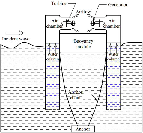
FIGURE 1. Schematic diagram of the symmetrical dual-chamber OWC wave energy converter.
The whole dual-chamber OWC WEC can be regarded as an oscillating single floating body, and the air turbine generator set is simplified as an ideal PTO damping. Under the action of linear airy wave, the WEC mainly relies on the heave motion to absorb and convert wave energy, which can be simplified as a single-degree-of-freedom damped forced vibration. As shown in Figure 2, a cylindrical coordinate system
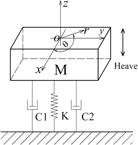
FIGURE 2. Forced vibration model of a single floating body.
It is assumed that the WEC with a mass
In the vertical direction, it can be obtained as follows, according to Newton’s second law:
where
The hydrodynamic coefficients
In the single-degree-of-freedom damped forced vibration system, the heave natural frequency
The WEC outputs power through two pneumatic PTO systems. The power absorbed by the WEC from the wave is related to the PTO damping. The time-averaged absorbed power can be expressed as
The absorbed power
The width of the wave crest through the dual-chamber OWC WEC is set as
where
Then, the primary energy conversion characteristic of the WEC, also known as capture width ratio (CWR), can be expressed as follows:
Motion response and capture performance of a dual-chamber OWC
In order to explore the influence of different shapes and geometries on the hydrodynamic response and capture performance of the dual-chamber OWC WEC, rectangular dual-chamber OWC WECs with different structure sizes were designed. The effects of the draft of the WEC and the bottom shape of the floating body on the motion response and capture performance of the WEC were compared and studied.
Capture performance of the dual-chamber OWC with different geometric sizes
It is assumed that the top view of the structure rigidly connected with the double pipes and the buoyancy module is a square, and its side length is
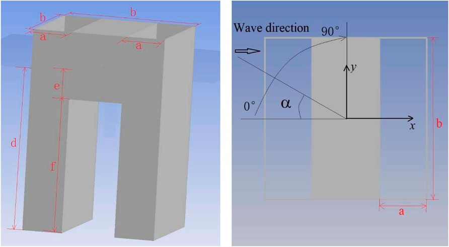
FIGURE 3. Dimensional parameters of the dual-chamber OWC WEC model.
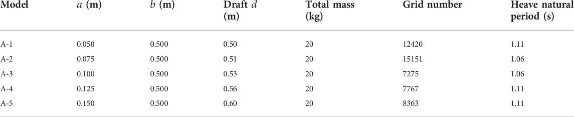
TABLE 1. Parameters of five models with the chambers of different geometric sizes.
The dual-chamber OWC WEC models were established using hydrodynamic software AQWA, the surface mesh was divided, and five models were obtained, as shown in Figure 4. The seawater density
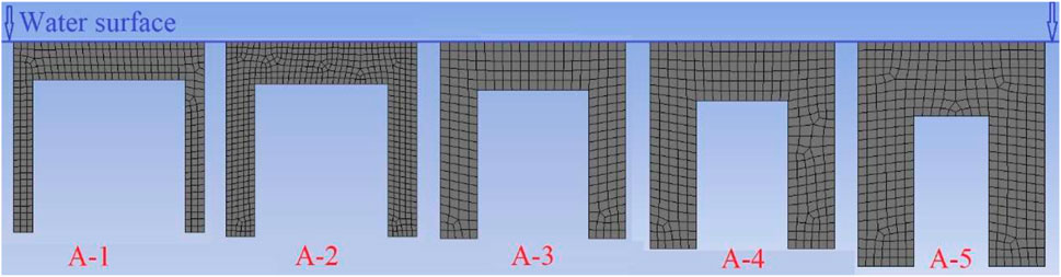
FIGURE 4. Five dual-chamber OWC WEC models with the chambers of different geometric sizes.
First, the capture performance is studied when the incident wave direction and the model form different angles
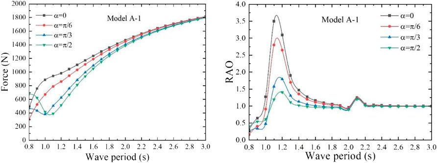
FIGURE 5. Wave force on model A-1 (left) and the heave RAO of it (right).
Since the structure of the front and rear air chambers of the dual-chamber OWC model is the same, the same PTO damping is applied to the front and rear air chambers. When the applied aerodynamic PTO damping is equal to the heave radiation damping coefficient, the maximum absorbed power can be obtained (Li et al., 2022). In order to obtain the maximum CWR, the sum of the PTO damping is set as 60 Ns/m, according to the heave radiation damping coefficient of the models A-1. The absorbed power and the incident wave power of the model are calculated according to the aforementioned formula so as to calculate the CWR of model A-1. Therefore, the capture performance of the model A-1 under different angles
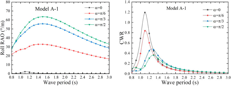
FIGURE 6. Roll RAO and the CWR of model A-1 with different incident wave angles
Under the action of the unit amplitude incident wave, the angle
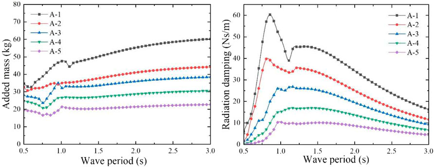
FIGURE 7. Heave added mass and radiation damping coefficient of the five dual-chamber OWC models with the chambers of different geometric sizes.
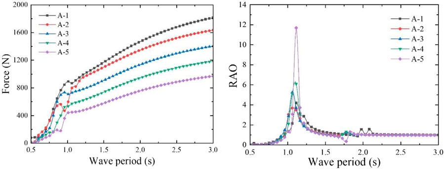
FIGURE 8. Wave force on the five dual-chamber OWC models (left) and their heave RAO (right).
In order to obtain the maximum capture performance, different aerodynamic PTO damping (60, 40, 27, 17, and 10 Ns/m) was applied to the five models, according to the heave radiation damping coefficient. The absorbed power and CWR of these models were obtained using the mathematical calculation program. The CWR curves are shown in Figure 9, and the peak capture performance of the five models is shown in Table 2. According to the calculation results, when the incident wave period is 1.06 s, the heave motion response of models A-2 and A-3 is the most severe, and CWR of both the models reaches the peak values of 1.109 and 1.266, respectively. When the wave period is 1.11 s, the models A-1, A-4, and A-5 present the most severe heave motion response, and their CWRs all reach their peak values of 1.153, 1.183, and 1.208, respectively, so the model A-3 has the largest CWR. The calculated heave natural period of the water column in the rectangular vertical pipe of each model is shown in Table 2. The heave natural period of the water column is far greater than that of the dual-chamber OWC model, so the operating wave period of the WEC model should be appropriately small and close to the heave natural period of the model. The dual-chamber OWC model mainly relies on the overall heave motion to capture the wave energy and outputs the energy through the pneumatic PTO near the operating wave period. According to the oscillatory characteristics of the water column in the pipe, under the effect of the PTO damping, the water column in the pipe is basically stationary, and the relative motion between the water column and the rectangular pipe can form an oscillating water column, which is also the working characteristic of the WEC model.
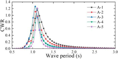
FIGURE 9. CWR of five models with different dual-chamber geometry sizes.
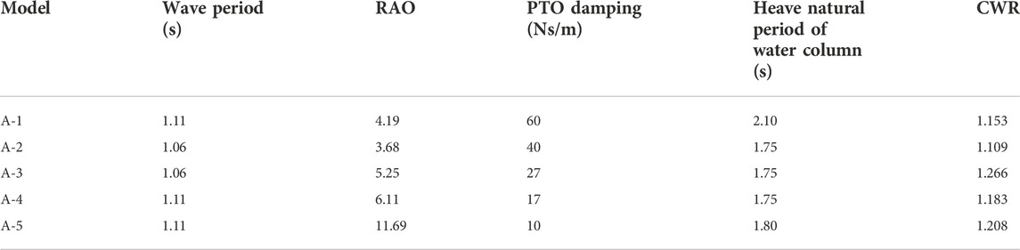
TABLE 2. Peak capture performance of five dual-chamber OWC models.
Capture performance of a dual-chamber OWC with different drafts
In order to explore the influence of the draft of the dual-chamber OWC WEC model on its capture performance, five models with different total masses were designed based on model A-3, which were marked as model B. Five models were obtained by adding a certain weight, as shown in Table 3. The length
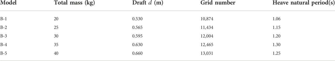
TABLE 3. Model B with different drafts.
Similarly, under the action of the unit amplitude incident wave, the angle
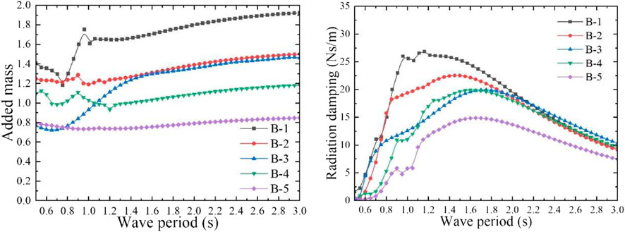
FIGURE 10. Dimensionless heave added mass and radiation damping coefficient of model B with different drafts.
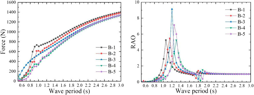
FIGURE 11. Wave excitation force on model B (left) and their heave RAO (right).
In order to obtain the optimal CWR of model B, different aerodynamic PTO damping (27, 20, 20, 20, and 15 Ns/m) was applied to model B with different total mass. The absorbed power and CWR can be calculated by the mathematical calculation program, the CWR curve is shown in Figure 12, and the peak capture performance of the model B is shown in Table 4. It can be observed from the calculation results that when the incident wave period is approximately equal to the heave natural period, the model has the largest heave response RAO, and when the PTO damping equivalent to the maximum radiation damping coefficient is applied, the model can achieve the largest CWR. In this case, since the wave period is far away from the heave natural period of the water column in the pipe and the aerodynamic PTO damping is applied to the water column, the water column is almost motionless. Therefore, the relative motion between the whole floating body model and the water column in the pipe is generated to form the oscillating water column to output pneumatic energy. For model B, with the increase of the total mass, the CWR gradually decreases, and the optimal response period range becomes narrower. However, when the total mass of model B is doubled, namely, model B-5, the CWR increases instead, and the maximum value reaches 1.332. Although the peak value of the CWR has increased a little, the total mass has doubled, which means that the cost has increased significantly. Therefore, the draft and total mass of such model should be minimized to control the cost, and they should be reasonably designed according to the wave period range of the operating sea area to make it work within the optimal response period range. The numerical free decay tests of model B with different drafts were performed, and the oscillation time series of the models were recorded. The time series of the simulated free decay tests in heave motion are shown in Figure 13. The natural period of the model can be evaluated by the free decay test results (Çelik and Altunkaynak, 2020). It is consistent with the natural frequency calculated in the frequency domain.
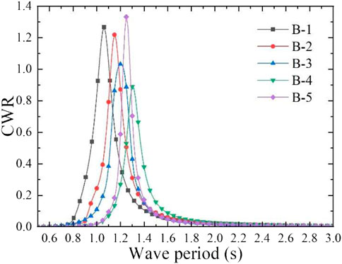
FIGURE 12. CWR of model B with different drafts.

TABLE 4. Peak capture performance of model B with different drafts.
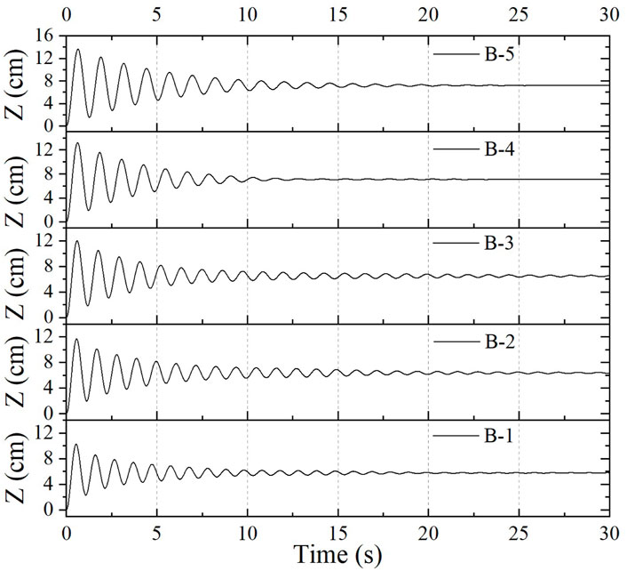
FIGURE 13. Time series of the simulated free decay test of model B with different drafts in heave motion.
Effect of bottom shape of the buoyancy module on capture performance of the dual-chamber OWC
In order to explore the effect of the bottom shape of the buoyancy module on the capture performance of the dual-chamber OWC WEC model, five models with different bottom shapes were designed by reference to model A-3. Among them, the flat-bottomed model, which is as same as model A-3 and B-1, is marked as model C, and the model with a wedge-shaped bottom, namely, a triangular prism, is marked as model D. The model, the height of whose bottom isosceles triangle is 0.15 m and the height of whose triangular prism is 0.5 m, is named as model D-1. The model, the height of whose bottom isosceles triangle is 0.25 m and the height of whose triangular prism is 0.3 m, is named as model D-2. The model whose bottom shape is semi-cylindrical is denoted as model E, and the semi-cylinder with a bottom semicircle radius of 0.15 m and a height of 0.5 m is denoted as model E-1, and the semi-cylinder with a bottom semicircle radius of 0.25 m and a height of 0.3 m is denoted as model E-2. The numerical model is established, and the mesh is divided, as shown in Figure 14. The WEC model parameters of five different bottom shapes of the buoyancy module are shown in Table 5. They have the same dual-chamber rectangular vertical pipes, the length
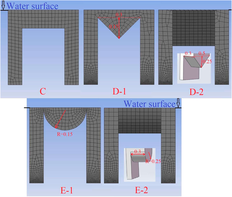
FIGURE 14. Dual-chamber OWC models with different bottom shapes of the buoyancy module.
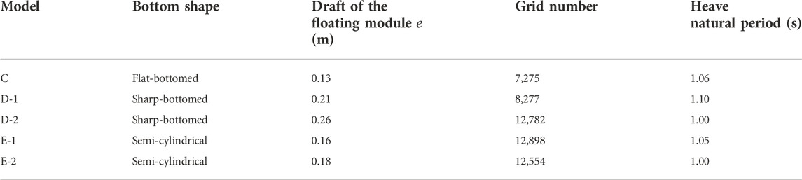
TABLE 5. Model parameters of five different bottom shapes of the buoyancy module.
The heave added mass and radiation damping coefficient of the model were calculated. As shown in Figure 15, the heave added mass increases slowly with the increase of the wave period as a whole, except for some regional fluctuations. As for the radiation damping coefficient, it increases first and then decreases with the increase of the wave period on the whole. When the wave period is greater than 1.1 s, there is little difference of the radiation damping coefficients among the five models, and they all decrease with the increase of the period. When the wave period is less than 1.0 s, the radiation damping coefficients of the five models are quite different, the smallest one is model C and the largest one is model D-2. As shown in Figure 16, under the action of the unit amplitude incident wave, the wave excitation force on these five models increases with the increase of the wave period as a whole, except for model D-2, which shows a significant fluctuation in a large period range. These five models have the same total mass and draft, so the difference of wave excitation force on them is very small. Due to the different bottom shapes of the buoyancy module, its draft
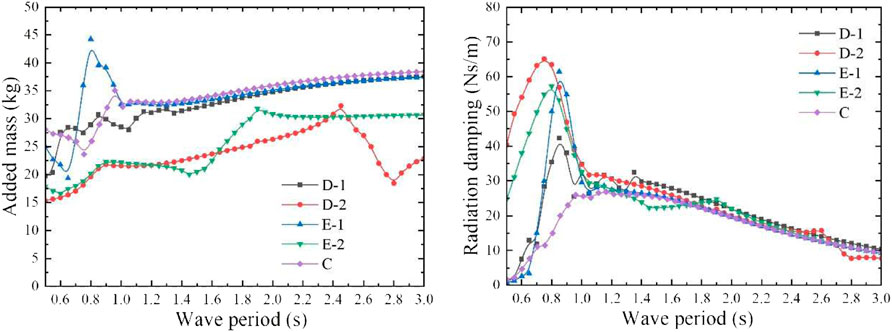
FIGURE 15. Heave added mass and radiation damping coefficient of the models with different bottom shapes.
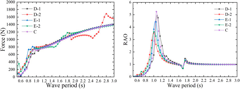
FIGURE 16. Wave excitation force on models with different bottom shapes (left) and their heave RAO (right).
According to the radiation damping coefficient of each model, different external aerodynamic PTO damping (27, 42, 65, 61, and 57 Ns/m) was applied to five models with different bottom shapes, as shown in Table 6. The CWR of each model calculated by the mathematical calculation program is shown in Figure 17, and the peak capture performance of the model is shown in Table 6. According to the calculation results, the peak CWR of each model is more than 1. When the wave period is close to the heave natural period of the model, the capture performance of the model is the best and the CWR of model C is 1.266. It is assumed that when the CWR is greater than 0.2, the wave period is taken as the effective response period of the model. The calculation results show that the effective response wave period range of model C is 0.90 s–1.25 s, the effective response wave period range of model D-1 is 0.90 s–1.40 s, the effective response wave period range of model D-2 is 0.80 s–1.40 s, the effective response wave period range of model E-1 is 0.85–1.40 s, and that of model E-2 is 0.85–1.35 s. It can be observed that the effective response period range of model C is the narrowest, while that of model D-2 is the widest. Therefore, the flat-bottom dual-chamber OWC model presents the best capturing performance, but the effective response period range is narrow, and it can be broadened by modifying the bottom shape to a wedge type.
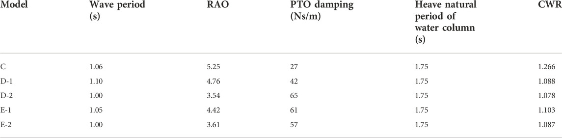
TABLE 6. Peak capture performance of these models with different bottom shapes.
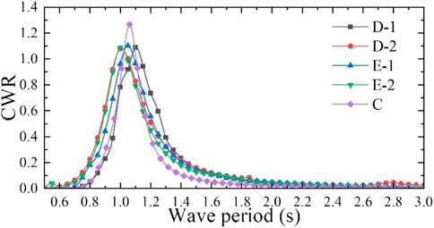
FIGURE 17. CWR of these five models with different bottom shapes.
Conclusion
In this study, a symmetric front and back floating OWC WEC with dual-air chambers is proposed. The dual-chamber pipes and the buoyancy module are welded as a whole, and it mainly heaves, surges, and pitches under the action of the incident waves. Relying on the heave motion of the overall floating body, the relative motion between the vertical pipe and the water column in it can be generated to output the pneumatic energy, so it can also be regarded as a pneumatic-type oscillating single floating body wave energy converter. The hydrodynamic characteristics and the capture performance of the dual-chamber OWC WEC models are studied by the numerical calculation method in this study. First, the influence of the angle
Data availability statement
The original contributions presented in the study are included in the article/Supplementary Material; further inquiries can be directed to the corresponding author.
Author contributions
ML and RW proposed the concept and research framework. ZY and ML performed the numerical analysis. ML wrote the manuscript draft. BW provided research advice.
Funding
This work was supported by the Natural Science Foundation of Jiangsu Province, China (Grant No. BK20201045), the National Natural Science Foundation of China (Grant Nos. U20A20106, 51906099, and 51879253), and the Scientific Research Fund for High-level Talents in Nanjing Institute of Technology (Grant No. YKJ201947).
Conflict of interest
The authors declare that the research was conducted in the absence of any commercial or financial relationships that could be construed as a potential conflict of interest.
Publisher’s note
All claims expressed in this article are solely those of the authors and do not necessarily represent those of their affiliated organizations, or those of the publisher, the editors, and the reviewers. Any product that may be evaluated in this article, or claim that may be made by its manufacturer, is not guaranteed or endorsed by the publisher.
References
Alves, M. A., Costa, I. R., Sarmento, A. J., and Chozas, J. F. (2010). “Performance evaluation of an axysimmetric floating OWC,” in The Twentieth International Offshore and Polar Engineering Conference, Beijing, China, June 2010 (OnePetro), 856–862. Available at: https://www.semanticscholar.org/paper/Performance-Evaluation-of-an-Axysimmetric-Floating-Alves-Costa/c81799e6dbcb5edf453d1f5050285430846d8743.
Çelik, A., and Altunkaynak, A. (2020). Determination of hydrodynamic parameters of a fixed OWC by performing experimental and numerical free decay tests. Ocean. Eng. 204, 106827. doi:10.1016/j.oceaneng.2019.106827
Elhanafi, A., Macfarlane, G., and Ning, D. (2018). Hydrodynamic performance of single–chamber and dual–chamber offshore–stationary Oscillating Water Column devices using CFD. Appl. Energy 228, 82–96. doi:10.1016/j.apenergy.2018.06.069
Falcão, A. F. de O. (2010). Wave energy utilization: A review of the technologies. Renew. Sustain. Energy Rev. 14, 899–918. doi:10.1016/j.rser.2009.11.003
Falcao, A. F. O., Henriques, J. C. C., and Candido, J. J. (2012). Dynamics and optimization of the OWC spar buoy wave energy converter. Renew. Energy 48, 369–381. doi:10.1016/j.renene.2012.05.009
Falcão, A. F. O., Henriques, J. C. C., Gato, L. M. C., and Gomes, R. P. F. (2014). Air turbine choice and optimization for floating oscillating-water-column wave energy converter. Ocean. Eng. 75, 148–156. doi:10.1016/j.oceaneng.2013.10.019
Falcão, A. F. O., and Henriques, J. C. C. (2016). Oscillating-water-column wave energy converters and air turbines: A review. Renew. Energy 85, 1391–1424. doi:10.1016/j.renene.2015.07.086
Gadelho, J. F. M., Rezanejad, K., Xu, S., Hinostroza, M., and Guedes Soares, C. (2021). Experimental study on the motions of a dual chamber floating oscillating water column device. Renew. Energy 170, 1257–1274. doi:10.1016/j.renene.2021.01.135
Gao, H., and Yu, Y. (2018). The dynamics and power absorption of cone-cylinder wave energy converters with three degree of freedom in irregular waves. Energy 143, 833–845. doi:10.1016/j.energy.2017.11.036
Gomes, R. P. F., Henriques, J. C. C., Gato, L. M. C., and Falcão, A. F. O. (2020). Time-domain simulation of a slack-moored floating oscillating water column and validation with physical model tests. Renew. Energy 149, 165–180. doi:10.1016/j.renene.2019.11.159
Guo, B., and Ringwood, J. V. (2021). Geometric optimisation of wave energy conversion devices: A survey. Appl. Energy 297, 117100. doi:10.1016/j.apenergy.2021.117100
Heath, T. V. (2012). A review of oscillating water columns. Phil. Trans. R. Soc. A 370, 235–245. doi:10.1098/rsta.2011.0164
Hong, D. C., Hong, S. Y., and Hong, S. W. (2004a). Numerical study of the motions and drift force of a floating OWC device. Ocean. Eng. 31, 139–164. doi:10.1016/s0029-8018(03)00118-5
Hong, D. C., Hong, S. Y., and Hong, S. W. (2004b). Numerical study on the reverse drift force of floating BBDB wave energy absorbers. Ocean. Eng. 31, 1257–1294. doi:10.1016/j.oceaneng.2003.12.007
Kofoed, J. P., Frigaard, P., Friis-Madsen, E., and Sørensen, H. Chr. (2006). Prototype testing of the wave energy converter wave dragon. Renew. Energy 31, 181–189. doi:10.1016/j.renene.2005.09.005
Li, M., Wu, R., Wu, B., Yang, Z., and Li, G. (2022). Hydrodynamic performance and optimization of a pneumatic type spar buoy wave energy converter. Ocean. Eng. 254, 111334. doi:10.1016/j.oceaneng.2022.111334
Masuda, Yoshio (1987). Experiences in pneumatic wave energy conversion in Japan. Tokyo, Japan: Engineering, 1–33. Available at: https://www.semanticscholar.org/paper/Experiences-in-Pneumatic-Wave-Energy-Conversion-in-Masuda-Mccormick/a5eb709ebe0dab1e1596eae9879634df59d3aecb.
Mustapa, M. A., Yaakob, O. B., Ahmed, Y. M., Rheem, C.-K., Koh, K. K., and Adnan, F. A. (2017). Wave energy device and breakwater integration: A review. Renew. Sustain. Energy Rev. 77, 43–58. doi:10.1016/j.rser.2017.03.110
Ning, D.-Z., Wang, R.-Q., Gou, Y., Zhao, M., and Teng, B. (2016a). Numerical and experimental investigation of wave dynamics on a land-fixed OWC device. Energy 115, 326–337. doi:10.1016/j.energy.2016.09.001
Ning, D.-Z., Wang, R.-Q., Zou, Q.-P., and Teng, B. (2016b). An experimental investigation of hydrodynamics of a fixed OWC Wave Energy Converter. Appl. Energy 168, 636–648. doi:10.1016/j.apenergy.2016.01.107
Ning, D.-Z., Zhao, X.-L., Zhao, M., Hann, M., and Kang, H.-G. (2017). Analytical investigation of hydrodynamic performance of a dual pontoon WEC-type breakwater. Appl. Ocean Res. 65, 102–111. doi:10.1016/j.apor.2017.03.012
Ning, D., Zhou, Y., Mayon, R., and Johanning, L. (2020). Experimental investigation on the hydrodynamic performance of a cylindrical dual-chamber Oscillating Water Column device. Appl. Energy 260, 114252. doi:10.1016/j.apenergy.2019.114252
Ning, D., Zhou, Y., and Zhang, C. (2018). Hydrodynamic modeling of a novel dual-chamber OWC wave energy converter. Appl. Ocean Res. 78, 180–191. doi:10.1016/j.apor.2018.06.016
Qiu, S., Liu, K., Wang, D., Ye, J., and Liang, F. (2019). A comprehensive review of ocean wave energy research and development in China. Renew. Sustain. Energy Rev. 113, 109271. doi:10.1016/j.rser.2019.109271
Rezanejad, K., Gadelho, J. F. M., Xu, S., and Guedes Soares, C. (2021). Experimental investigation on the hydrodynamic performance of a new type floating Oscillating Water Column device with dual-chambers. Ocean. Eng. 234, 109307. doi:10.1016/j.oceaneng.2021.109307
Rusu, E. (2014). Evaluation of the wave energy conversion efficiency in various Coastal Environments. Energies 7, 4002–4018. doi:10.3390/en7064002
Sheng, S., Wang, K., Lin, H., Zhang, Y., You, Y., Wang, Z., et al. (2017). Model research and open sea tests of 100 kW wave energy convertor Sharp Eagle Wanshan. Renew. Energy 113, 587–595. doi:10.1016/j.renene.2017.06.019
Sheng, W. (2019a). Motion and performance of BBDB OWC wave energy converters: I, hydrodynamics. Renew. Energy 138, 106–120. doi:10.1016/j.renene.2019.01.016
Sheng, W. (2019b). Power performance of BBDB OWC wave energy converters. Renew. Energy 132, 709–722. doi:10.1016/j.renene.2018.07.111
Wang, C., Zhang, Y., and Deng, Z. (2022a). A novel dual-chamber oscillating water column system with dual lip-wall pitching motions for wave energy conversion. Energy 246, 123319. doi:10.1016/j.energy.2022.123319
Wang, C., Zhang, Y., and Deng, Z. (2022b). Inclusion of a pitching mid-wall for a dual-chamber oscillating water column wave energy converter device. Renew. Energy 185, 1177–1191. doi:10.1016/j.renene.2021.12.084
Wang, R., Ning, D., and Zou, Q. (2020). Wave loads on a land-based dual-chamber Oscillating Water Column wave energy device. Coast. Eng. 160, 103744. doi:10.1016/j.coastaleng.2020.103744
Whittaker, T. J. T., and Mcpeake, F. A. (1986). Design optimization of axi-symmetric tail tube buoys. Lisbon: Springer Berlin Heidelberg.
Wu, B., Chen, T., Jiang, J., Li, G., Zhang, Y., and Ye, Y. (2018). Economic assessment of wave power boat based on the performance of “Mighty Whale” and BBDB. Renew. Sustain. Energy Rev. 81, 946–953. doi:10.1016/j.rser.2017.08.051
Wu, B., Li, M., Wu, R., Zhang, Y., and Peng, W. (2017). Experimental study on primary efficiency of a new pentagonal backward bent duct buoy and assessment of prototypes. Renew. Energy 113, 774–783. doi:10.1016/j.renene.2017.06.010
Xu, S., Rezanejad, K., Gadelho, J. F. M., Wang, S., and Guedes Soares, C. (2020). Experimental investigation on a dual chamber floating oscillating water column moored by flexible mooring systems. Ocean. Eng. 216, 108083. doi:10.1016/j.oceaneng.2020.108083
Keywords: wave energy, oscillating water column (OWC), dual-chamber, hydrodynamic performance, capture width ratio (CWR)
Citation: Li M, Yang Z, Wu R and Wu B (2023) Numerical study on the hydrodynamic performance of a symmetrical dual-chamber oscillating water column wave energy converter. Front. Energy Res. 10:1058186. doi: 10.3389/fenrg.2022.1058186
Received: 30 September 2022; Accepted: 31 October 2022;
Published: 13 January 2023.
Edited by:
Dezhi Ning, Dalian University of Technology, ChinaReviewed by:
Ray-Yeng Yang, National Cheng Kung University, TaiwanWang Chen, Tsinghua University, China
Copyright © 2023 Li, Yang, Wu and Wu. This is an open-access article distributed under the terms of the Creative Commons Attribution License (CC BY). The use, distribution or reproduction in other forums is permitted, provided the original author(s) and the copyright owner(s) are credited and that the original publication in this journal is cited, in accordance with accepted academic practice. No use, distribution or reproduction is permitted which does not comply with these terms.
*Correspondence: Rukang Wu, d3VydWthbmdAbmppdC5lZHUuY24=