 Pengyu Wang
 Jianfeng Zhao1*
 Kangli Liu
94% of researchers rate our articles as excellent or good
Learn more about the work of our research integrity team to safeguard the quality of each article we publish.
Find out more
ORIGINAL RESEARCH article
Front. Energy Res. , 16 January 2023
Sec. Smart Grids
Volume 10 - 2022 | https://doi.org/10.3389/fenrg.2022.1052789
This article is part of the Research Topic Operation and Control in Smart Electric Power Systems: Methods and Applications View all 5 articles
With the development of power grid technology, a large number of constant power loads (CPL) are introduced into the power grid system. The negative damping characteristic of CPL poses a great challenge to the stability of power grid under the condition of large signal disturbance. This paper focuses on the large signal stability and dynamic response characteristics of DC microgrid with CPL. The mixed potential function (MPF) method is adopted to model the large signal characterstic of load converter controlled by the traditional PI control strategy and the new virtual DC motor (VDM) control strategy. The large signal stability criteria and the asymptotic stability region of the DC microgrid system under the two control strategies are derived. The dynamic response characteristics of the DC microgrid are compared under three large signal operation conditions of the load step, load linear change and the load fault. The results show that VDM control strategy can effectively improve dynamic response characteristics of the DC microgrid system compared with those of PI control, and enhance the stability and anti-interference ability of the DC microgrid system.
With the development of world economy, the sustainable development of energy has become focus of attention of all countries. The integration of renewable energy generation and modern power grid is the core of world’s sustainable energy transformation. How to cope with large-scale renewable energy generation and grid connection has become an important challenge in the smart grid field (Ma et al.,2016). Due to the absence of higher harmonics and frequency fluctuations, DC microgrid has attracted wide attention due to its advantages such as high conversion efficiency and simple control method (Masoud et al.,2018). With continuous expansion of the scale of DC microgrid, a large number of power electronic converters have been applied, and a large number of constant power loads (CPL) have also been introduced (Zhi et al.,2016). A typical DC microgrid structure is shown in Figure 1, which includes energy storage module, new energy generation module, constant power load module, etc. As a typical non-linear load, the CPL has occupied an increasingly large proportion in the DC microgrid system. When multiple power electronic converters are cascaded in the closed-loop control system, the decoupling between sub-systems at all levels seems even difficult, such that traditional stability control analysis method cannot further meet the decoupling operation of multi-level system. Especially, in case of large signal operation conditions such as load step, load linear change and load fault, it is urgent to find a suitable stability analysis method for the multi-level system. At present, the multi-level system widely applies the traditional PI control strategy, when large signal disturbance occurs, the negative damping characteristic of CPL may heavily affect its stable operation (Zhi et al.,2016a; Li et al.,2019). Therefore, how to synthesize an advanced control strategy suitable for CPL and analyze its large signal stability has become a hot topic in research field of the DC microgrid.
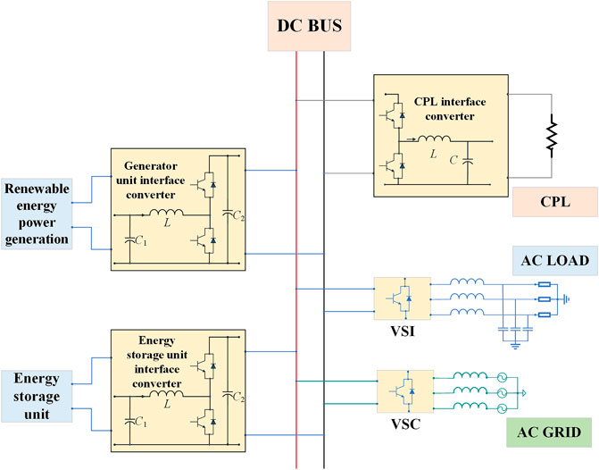
FIGURE 1. Structure diagram of DC microgrid with CPL.
In order to overcome negative damping characteristic of the CPL, the virtual DC motor control strategy (VDM) has become a better choice. This control strategy can add virtual inertia J and damping characteristic D into the control link of the DC converter, so that the converter could behavior the rotational inertia and damping characteristics of DC motor. Above that, the anti-interference ability of power system can be improved, and the problem of large overshoot and long-time transient response of the system with PI control can be solved. In (Zhi et al.,2020), a VDM control strategy of energy router is proposed, by applying the virtual synchronous motor and virtual DC motor to control AC side and DC side converters, respectively. However, the control strategy adopts fixed parameters and does not consider the impact of large signal change. In (Sheng et al.,2015), a VDM control strategy is proposed for the load side DC converter, in order to suppress the DC bus voltage fluctuation when the load changes, but can not meet practical engineering application, due to lack of the feedback link and only considering the pure resistive load. In (Wu et al.,2017), a VDM control strategy is proposed for the photovoltaic power converter, whereas the stability is not analyzed for the load side converter under large signal fluctuations.
The study of DC microgrid stability plays an important role in improving power quality and enhancing safe and stable operation of the power grid. At present, the research on the stability of DC microgrid is mainly divided into two categories such as the small signal stability analyais and the large signal stability analysis (Kakigano et al.,2010; Liu et al.,2013). The former neglects part of the nonlinear characteristics of the system, so as to establish a linearized model near the steady-state operating point. However, the nonlinear characteristic cannot be ignored for the multi-level system with CPL, and the large signal stability analysis method is thus acquired. The traditional large signal stability analysis methods mainly include Lyapunov direct method, phase plane method and mixed potential function (MPF) method (Marx et al.,2012). For the large signal stability analysis of multi-level system, Lyapunov direct method and phase diagram method will face problems such as modeling difficulties, large amount of analysis computation, whereas the novel mixed function method seems more suitable for large signal stability analysis of the multi-level system. In (Liu and Zhou, 2011), the large signal stability of multi-level LC filter circuit is analyzed with MPF, but the large signal stability criterion at the device level is not studied. In (Huang et al.,2017), the large signal stability of photovoltaic grid connected converter is analyzed with MPF, whereas the obtained stability criterion is quite complex due to the coordinate transformation in the control link. In (Jiang et al.,2019), the MPF is adopted to analyze the large signal stability of hybrid DC microgrid with PI control, but the serious nonlinearity of system with CPL is not studied. The above papers show that the MPF method has advantages such as simplified modeling, clear physical meaning, fast calculation, etc., and needs further study due to its infancy in the stability analysis of DC microgrid.
To sum up, the VDM control strategy can effectively improve the dynamic response performance and anti-interference ability of the system, which can be introduced into the control link of CPL converter, in order to improve the negative damping characteristics of DC microgrid. The author has proposed a VDM control strategy based on parameter adaptation (Wang et al.,2021). In this paper, the author study the large signal stability of DC microgrid system with VDM-controled CPL converter, the MPF method is adopted to model the large signal characterstic of load converter, derive the large signal stability criteria and the asymptotic stability region of DC microgrid, and analyze the dynamic response characteristics of thesystem under three large signal operation conditions of load step, load linear change and load fault.
The MPF is a scalar function of capacitor voltage and inductor current in electrical network system, in order to describe the large signal stability of dynamic equilibrium points in two port nonlinear RLC networks (Zheng et al.,2020). In which, if the capacitor voltage and inductance current in the electrical network can form a complete variable set, or the voltage and current of each branch in the electrical network can be determined by independently selecting variables, the electrical network can be formulated in the MPF expressed in Eq. 1.
Where, A(i) is the sum of the current potential functions of the non-energy storage element branches in the electrical network, B(v) is the sum of the voltage potential functions of the non-energy storage element branches in the electrical network, and (i, γv-α) is the sum of the energy contained in the capacitance and other non-energy storage elements in the electrical network. According to the MPF theory, the correctness criterion of the mixed potential function is shown in Eq. 2, if the obtained mixed potential function meets both the criteria shown in Eq. 2, the correctness of the mixed potential function of the system can be verified, and on this basis, the large signal stability condition and the specific large signal asymptotic stability region can be solved.
Since the latter stage in multi-level system can be equivalent to the CPL of former stage, the single-stage DC microgrid system with CPL is taken as the research object in this paper, as shown in Figure 1. This section gives priority to the large signal modeling of PI controlled CPL converter, because the VDM is an optimal control strategy on bassis of the PI control. In which, the VDM control strategy adopts VDM control module to provide a reference current value, instead of the voltage outer loop in PI control. It is necessary to model and analyze the load converter controlled by PI, before further analyzing the load converter controlled by VDM. Among them, the bi-directional Buck-Boost converter is used as the constant power load interface converter. Figure 2 shows the control block diagram of DC-DC converter based on PI control, supposing that the DC bus voltage of the DC microgrid is U1, the power value of constant power load is P0, the terminal voltage value of CPL is U0, the duty ratio of bi-directional Buck-Boost converter is D, the input current of converter is I1, the output current is I0, the inductance current of converter is i, and the energy storage capacitor voltage is v.
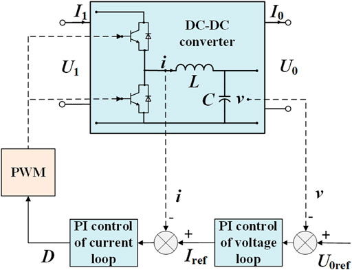
FIGURE 2. Control structure diagram of DC-DC converter based on PI control.
Assuming that the bi-directional Buck-Boost converter controlled by PI operates in Buck mode, the mathematical model and large signal average model of the converter are shown in Eq. 3.
Then the MPF model of the bi-directional Buck-Boost converter with CPL is built. As shown in Figure 2, the non-energy storage elements in this model include the DC bus voltage U1 and the constant power load P0. Assuming that each component is an ideal component without equivalent resistance, the current potential function P(i) of the non-energy storage element, the voltage potential function P(v) of the non-energy storage element, and the energy function PC of the energy storage capacitor C in the system can be formulated as follows.
Further, the MPF P (i,v) of the converter system can be obtained in Eq. 5, by substituting of the three terms in Eq. 4.
Where,
By substituting Eq. 5 into Eq. 2 for verification, it can be clearly seen that the function meets the correctness determination conditions described in Eq. 2, so the formulation is correct. By substituting Eq. 6 into Eq. 5, the MPF expression P (i,v) of the converter under PI control can be formulated in Eq. 7.
The basic principle of virtual DC motor (VDM) control is adding virtual damping J and moment of inertia D to the outer loop of converter PI control, so that it can behavior as the damping characteristics of DC motor externally, and the system presents the negative damping characteristics of CPL under large signal conditions. The converter control block diagram with VDM control is shown in Figure 3 and consists of three parts. Herein, the power calculation module is shown in Figure 3A, which calculates the difference between actual DC bus voltage and reference voltage by PI and multiplies it with the reference voltage to get the difference between mechanical power and output active power of the converter. The actual mechanical power can be obtained by adding the calculation result and the rated output power of the converter. Figure 3B shows the current tracking module, which sends the reference value of inductance current calculated by the previous module to the PWM module to obtain the switch drive signal. Figure 3C shows the VDM control module, inwhich the virtual DC motor model is built up according to the mechanical equation and armature equation of the DC motor, so that the DC converter has the moment of inertia and damping coefficient, and has a certain anti-interference ability when the CPL voltage fluctuates. Compared with the control block diagram of the DC-DC converter based on PI control shown in Figure 2, the VDM control strategy uses the power calculation module in series with the VDM control module to replace the voltage loop PI control module, and thus realizes the introduction of virtual torque and damping coefficient.
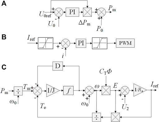
FIGURE 3. Schematic diagram of VDM control strategy. (A) Power calculation module. (B) Current tracking module. (C) VDM control module.
In the VDM control module, the mechanical torque Tm of the virtual DC motor can be obtained after the mechanical power Pm is divided by the rated angular speed. According to the above mechanical equation and electromagnetic equation, the actual angular velocity of DC motor can be obtained, it is the mechanical part of VDM control to achieve the torque and speed balance of virtual motor rotor. On this basis, the reference value Ia of the converter output current is obtained through the armature equation, and the electromagnetic power Pe of the motor is obtained by multiplying it with the induced electromotive force E. After relevant operation, the electromagnetic torque Te is obtained and the negative feedback is conducted, it is the electrical part of VDM control, which converts the torque balance of the motor into the balance of the output voltage to enhance the inertia of the CPL voltage and improve its anti-interference capability. From Figure 3A, the expression of the VDM control input Pm can be expressed in Eq. 8.
As shown in Figure 3C, the expression of the inductance current reference value Iref can be obtained in Eq. 9.
Where,
Where,
According to the MPF theory, if the function satisfies the two stability criteria shown in Eq. 12, the system is judged to be in a large signal stable state. All the solutions satisfying both criteria approach to the steady-state operating point, which can satisfy the large signal stability of the system (Peng et al.,2019). Furthermore, according to Lyapunov’s second method, when P*(i,v) is positive definite and dP*(i,v)/dt is negative definite, the asymptotic stability region of the electrical network system under large signal can be obtained.
Where, μ1 and μ2 denote the minimum eigenvalue of the second order partial derivative matrix of voltage and current. Pi is the first order partial derivative of P (i,v) with respect to current. Pv is the first order partial derivative of P (i,v) with respect to voltage. Aii is the second order partial derivative of the current potential function in P (i,v) with respect to current. Bvv is the second order partial derivative of the voltage potential function in P (i,v) with respect to voltage. The expression of each component is shown in Eq. 13.
The system energy function P*(i,v)in Lyapunov form can be formulated in Eq. 14. Furthermore, the asymptotic stability region of the system is thus derived to analyze the large signal stability.
It can be seen from the previous analysis that P (i,v) shown in Eq. 5 is the standard form of the MPF of the DC microgrid. The MPF forms of VDM control converter and PI control converter are identical, except for the difference in the operational expression of duty cycle D. The stability criterion I of VDM control converter is the same as that of PI control converter. The influence of the two control strategies on P (i,v)is that the expression of duty cycle D is different. Therefore, the stability criterion under the two control strategies is comprehensively analyzed. By substituting Eq. 5 into Eq. 1, the MPF expression of DC converter can be obtained in Eq. 15.
The second order partial conductance Aii(i) and Bvv(v) of current potential function and voltage potential function are further calculated in Eq. 16.
By substitute Eq. 16 into Eq. 13, the minimum eigenvalue of the second order partial derivative matrix of voltage and current μ1 and μ2 are further obtained as shown in Eq. 17.
According to the above obtained large signal stability criterion I in Eq. 12, the converter control parameters should meet the following conditions shown in Eq. 18, where Rp is the load value of CPL.
According to the stability criterion Ⅱ, by substituting Eq. 5 into Eq. 14, the Lyapunov energy function P*(i,v) of the microgrid system can be obtained in Eq. 19.
Where,
When
Due to the expression of duty cycle D is different under the two control strategies, Eq. 7 and Eq. 10 need to be analyzed respectively. Since there is an integral link in the calculation of duty cycle D, when | i | →∞ or | v | →∞, D →∞ is satisfied. Therefore, the sum of terms 1 and 2 and terms 4 and 5 in Eq. 21 approaches infinity, and the value of the mixed potential function satisfies P*(i,v) → ∞. In conclusion, since the large signal model of the microgrid system meets the stability criterion II, the large signal stability of the control system can be achieved, when the control parameters are designed according to the stability criterion I. Furthermore, the expression dP*(i,v)/dt of the reciprocal of the Lyapunov energy function with respect to time can be obtained in Eq. 22.
In order to verify the superiority of VDM control over PI control in improving the large signal stability of DC microgrid, a DC microgrid simulation system with CPL is built up as shown in Figure 1. The hardware parameters and power scale of the DC microgrid simulation model are determined, and the control parameters of the DC converter are optimized according to the above stability criterion I, pecific system parameters are shown in Table 1. Amongst, the CPL converter adopts PI control and VDM control, respectively. Based on the above large signal stability criterion theory, the energy function and asymptotic stability region of DC microgrid under the two control modes are further analyzed, and the asymptotic stability region under the two control modes is compared. Wherein, U0ref is the rated voltage of constant power load set at the steady-state operating point.
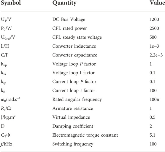
TABLE 1. DC microgrid system parameters.
PI and VDM control strategies are used to control the converter, respectively. The above control parameters are added into the MPF method for analyzing the large signal stability of DC microgrid system. The results of DC microgrid system under PI control and VDM control are shown in Figures 4–7. Figure 4 shows the MPF expression P (i,v) under two control strategies, where Figure 4A is the result of Eq. 7, and Figure 4B is the result of Eq. 11. It can be seen from Figure 4 that the VDM control strategy inhibits the value of the mixed potential function, reducing it to 10%. Figure 5 shows the Lyapunov energy function P*(i,v) under two control strategies, where Figure 5A and Figure 5B are the result of Eq. 14. It can be seen from Figure 5 that the VDM control strategy inhibits the value of Lyapunov energy function, reducing it to 1%. Figure 6 shows the derivative of Lyapunov energy function dP*(i,v)/dt under two control strategies, where Figure 6A and Figure 6B are the result of Eq. 22. It can be seen from Figure 6 that the derivative of the energy function is effectively suppressed by the VDM control strategy, reducing it to 0.1%.
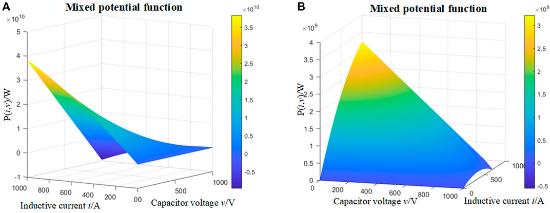
FIGURE 4. Mixed potential function under PI control and VDM control. (A) P (i,v) under PI control. (B) P (i,v) under VDM control.
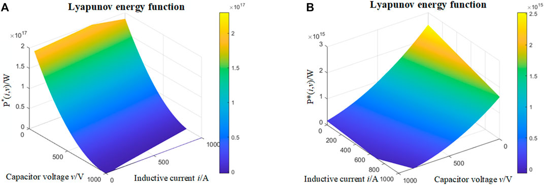
FIGURE 5. Lyapunov energy function under PI control and VDM control. (A) P*(i,v) under PI control. (B) P*(i,v) under VDM control.
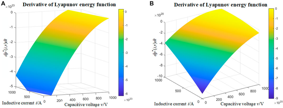
FIGURE 6. Derivative of Lyapunov energy function under PI control and VDM control. (A) dP*(i,v)/dt under PI control. (B) dP*(i,v)/dt under VDM control.
Furthermore, the asymptotic stability region of the system is derived, when P*(i,v) is positive and dP*(i,v)/dt is negative, the asymptotic stability region of the control system can be obtained. Figure 7 shows the asymptotic stability region of the DC microgrid system under the two control strategies. Figure 7A shows the asymptotic stability region of the PI control system. It can be seen that under the control parameters, the steady-state operating point of system is located in the asymptotic stability region, and the CPL converter can achieve large signal stability through PI control. However, under the condition of high rated power, there is a system range beyond the asymptotic stability region, within which the load converter will have serious problems such as discrete control, large signal instability and even system collapse. If the scope of the asymptotic stability region can be further expanded, the large signal stability of higher rated power CPL can be achieved, and thus improve the redundancy and stability of the DC microgrid system under high power conditions. Figure 7B shows the asymptotic stability region of the VDM control system. It can be seen that under the control parameters, the CPL converter can achieve large signal stability through VDM control. Compared with the traditional PI control, the VDM control strategy expands the asymptotic stability region and improves the large signal stability of the system under high power conditions. The redundancy and stability of DC microgrid system under high power conditions are optimized.
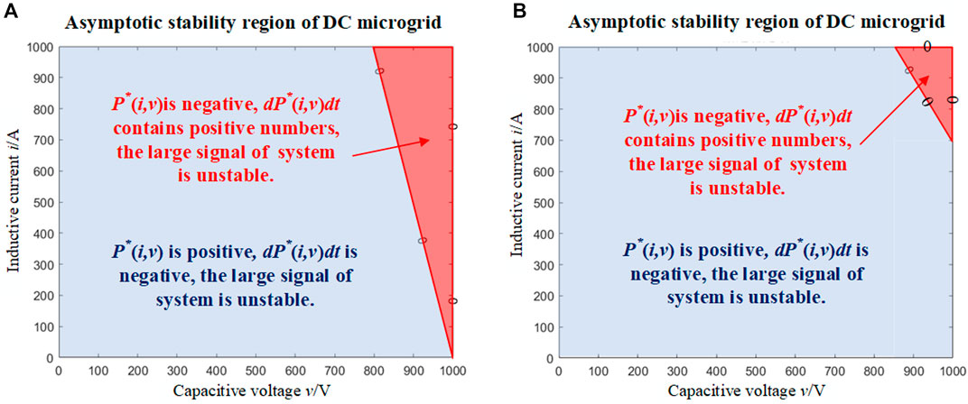
FIGURE 7. Asymptotic stability region under PI control and VDM control. (A) Asymptotic stability region under PI control. (B) Asymptotic stability region under VDM control.
In order to verify the optimization of dynamic response characteristics of VDM control strategy compared with traditional PI control, a simulation platform of DC microgrid with CPL is built on MATLAB/Simulink. Three big signal conditions are designed, including CPL load step, CPL load linear change and CPL load fault. The dynamic response characteristics of DC microgrid system controlled by VDM and PI are compared and simulated, and the control effects of traditional PI control strategy and VDM control strategy are analyzed.
In the operation of DC microgrid, load step is the most common large signal condition. It is assumed that CPL will be connected to the power grid for operation at 0.1s. At 0.3s, CPL rated voltage jumps from 500 V to 600 V. At 0.5 s, the rated voltage of CPL drops from 600V to 400 V.
The dynamic response characteristics of the DC microgrid with PI and VDM control strategies under the load step conditions are shown in Figures 8–10. Figure 8 shows that the VDM control can more effectively reduce the reverse impulse voltage when CPL load fluctuates, and the peak voltage decreases by about 30%. It can be seen from Figure 9 that VDM control can more effectively reduce the steady-state recovery time when the load fluctuates, and the steady-state response time is reduced by about 0.03 s. The comparison of DC bus voltage between PI control and VDM control is shown in Figure 10, which illustrate that VDM control reduces the peak voltage impact, effectively suppresses the DC bus voltage fluctuation, and reduces the steady-state response time. In conclusion, under the working condition of CPL load step, VDM control can more effectively restrain the voltage fluctuation of DC bus side and load side than traditional PI control, accelerate the system steady state recovery, and improve the stability of converter control system.
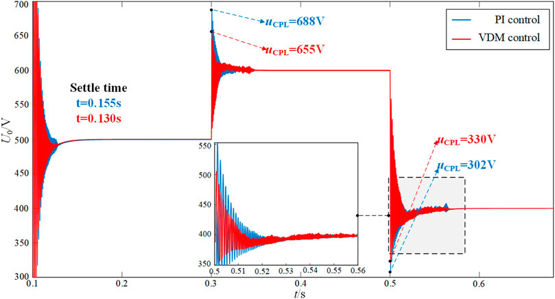
FIGURE 8. Comparison diagram of CPL voltage under CPL load step condition.
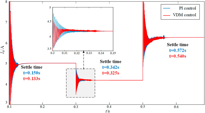
FIGURE 9. Comparison diagram of CPL current under CPL load step condition.
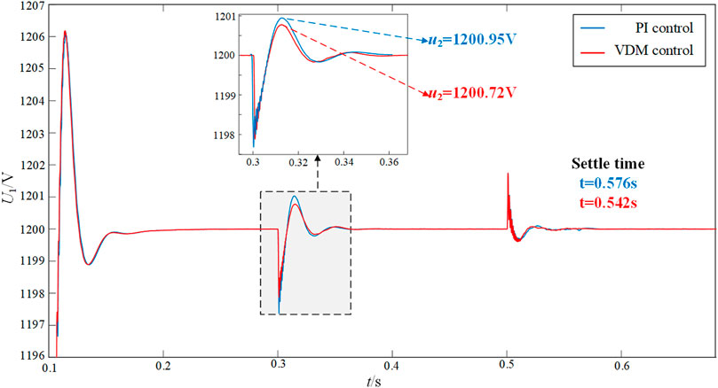
FIGURE 10. Comparison diagram of DC bus voltage under CPL load step condition.
In the operation of DC microgrid, there will be a linear change of CPL value. Assume that at 0.1 s, CPL is connected to the grid for work. At 0.2 s, the rated voltage of CPL jumps from 500 V to 550 V, and decreases linearly to 450 V within 0.2 s. At 0.4 s, the rated voltage of CPL recovers to 500 V
Under the condition of linear load change, the dynamic response characteristics of the DC microgrid system controlled by PI and VDM are shown in Figures 11–13. Figure 11 shows that the reverse impulse voltage is greatly suppressed by VDM control, and the peak voltage is reduced by about 70%. In the process of CPL continuous change, PI control has obvious oscillation process, while VDM control is relatively stable, and the oscillation amplitude is greatly reduced. It can be seen from Figure 12 that the VDM control greatly suppresses the reverse impulse current, reducing the peak current by about 70%, and reducing the steady-state response time on the load side by about 0.05s. The comparison of CPL DC bus voltage between PI control and VDM control is shown in Figure 13, which illustrate that VDM control significantly suppresses the DC bus voltage fluctuation and shortens the steady-state response time. In conclusion, under the working condition of linear change of CPL load, VDM control can more effectively restrain the voltage fluctuation of DC bus side and load side than traditional PI control, and speed up the system steady-state recovery, thus improving the stability of converter control system.
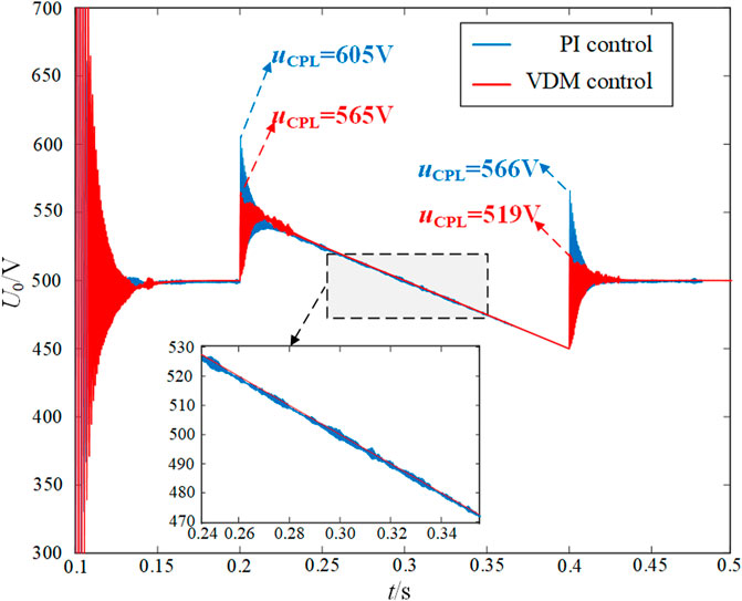
FIGURE 11. Comparison diagram of CPL voltage under CPL load linear change condition.
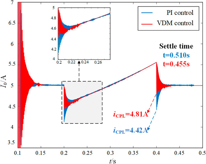
FIGURE 12. Comparison diagram of CPL current under CPL load linear change condition.
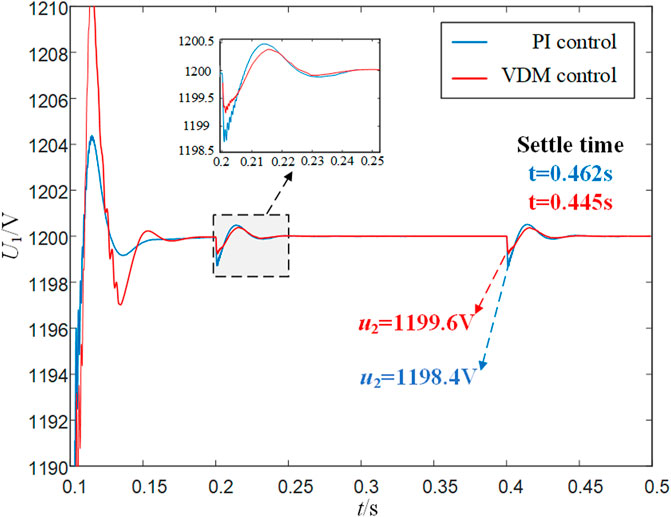
FIGURE 13. Comparison diagram of DC bus voltage under CPL load linear change condition.
During the operation of DC microgrid, there is a working condition where CPL fault causes continuous fluctuation of load value. Assume that at 0.1 s, CPL is connected to the grid for work. At 0.2 s, CPL rated voltage fluctuates sine wave from 500 V for 0.2 s. At 0.4 s, the rated voltage of CPL recovers to 500 V.
Under load fault condition, the dynamic response characteristics of PI control and VDM control DC microgrid system are shown in Figures 14, 15. It can be seen from Figure 14 that the VDM control effectively suppresses the voltage fluctuation of load cut in, and buffers the load voltage for a period at the beginning and end of the sinusoidal fluctuation. The comparison of CPL DC bus voltage between PI control and VDM control is shown in Figure 15. It can be seen that VDM control makes the DC bus voltage have a certain damping characteristic when the CPL load fluctuates sine wave, effectively suppressing the interference of irregular load fluctuations on the DC bus voltage. In conclusion, under the working condition of CPL load sinusoidal fluctuation, VDM control can more effectively restrain the influence of load fluctuation on load side voltage and DC bus voltage than traditional PI control. Thus, the grid system has virtual inertia and damping characteristics, and the stability of the converter control system is improved.
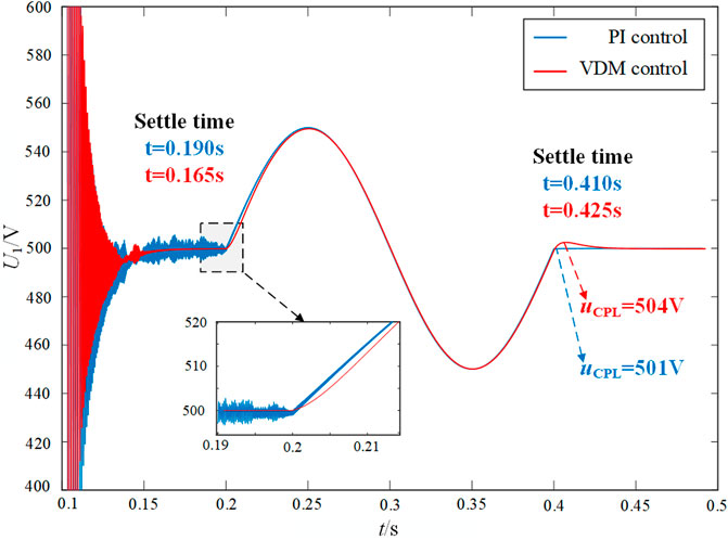
FIGURE 14. Comparison diagram of CPL voltage under CPL load fault condition.
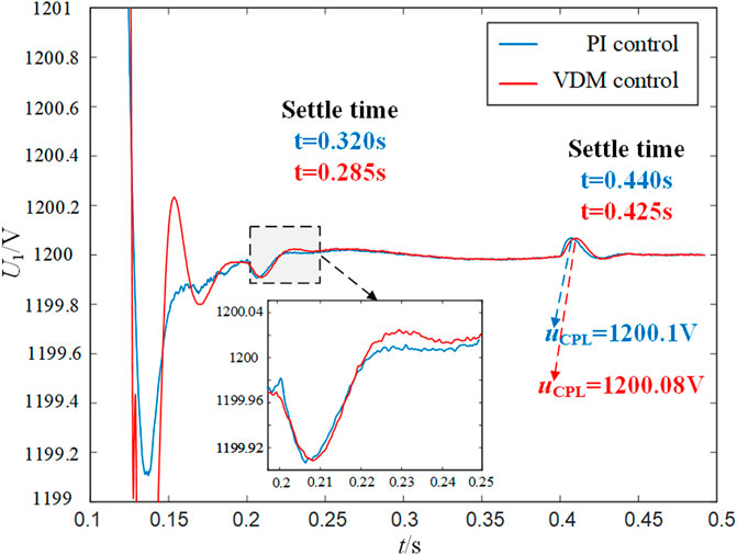
FIGURE 15. Comparison diagram of DC bus voltage under CPL load fault condition.
Since a large number of constant power loads exist in the DC microgrid system. It quite easily makes the DC bus voltage and load side voltage and current occur oscillation, and endanger the safe and stable operation of the system, due to its negative damping characteristics. In this paper, the MPF method is adopted to establish the large signal model of the DC converter under the traditional PI control and the new VDM control. The large signal stability of DC micro grid system under two control strategies are analyzed. The large signal stability criterion and asymptotic stability region are derived furtherly. The results show that VDM control can expand the large signal asymptotic stability region and improve the stability range of the power grid system. Furthermore, the dynamic response characteristics of the DC microgrid controlled by PI and VDM are compared under three large signal conditions such as CPL load step, CPL load linear change and CPL load fault. The results show that the VDM control strategy can effectively suppress the reverse impulse voltage and current when the load fluctuates, and the maximum suppression rate can reach 70%. The VDM control strategy significantly optimizes the dynamic response characteristics of the DC microgrid system, improves the stability and anti-interference ability, and has a good application prospect and practical value.
The raw data supporting the conclusions of this article will be made available by the authors, without undue reservation.
PW contributed to the theoretical analysis and simulation research of this paper. All authors participated in the writing and editing of manuscript.
This work was supported by the National Natural Science Foundation of China (51877042) and Project funded by China Postdoctoral Science Foundation (2020T130094).
The authors declare that the research was conducted in the absence of any commercial or financial relationships that could be construed as a potential conflict of interest.
All claims expressed in this article are solely those of the authors and do not necessarily represent those of their affiliated organizations, or those of the publisher, the editors and the reviewers. Any product that may be evaluated in this article, or claim that may be made by its manufacturer, is not guaranteed or endorsed by the publisher.
Huang, M., Peng, Y., Tse, C, K., Liu, Y., Sun, J., and Zha, X. (2017). Bifurcation and large-signal stability analysis of three-phase voltage source converter under grid voltage dips. IEEE Trans. Power Electron. 32 (11), 8868–8879. doi:10.1109/tpel.2017.2648119
Jiang, J., Liu, F., Pan, S., Zha, X., Liu, W., Chen, C., et al. (2019). A conservatism-free large signal stability analysis method for DC microgrid based on mixed potential theory. IEEE Trans. Power Electron. 34 (11), 11342–11351. doi:10.1109/tpel.2019.2897643
Kakigano, H., Miura, Y., and Ise, T. (2010). Low-voltage bipolar-type DC microgrid for super high quality distribution. IEEE Trans. Power Electron. 25 (12), 3066–3075. doi:10.1109/tpel.2010.2077682
Li, X., Li, Z., and Guo, L. (2019). Flexible control and stability analysis of AC/DC microgrids clusters. Proc. CSEE 39 (20), 5948–5961. doi:10.13334/j.0258-8013.pcsee.181950
Liu, S., Zhou, L., and Lu, W. (2013). Simple analytical approach to predict large-signal stability region of a closed-loop boost DC-DC converter. IET Power Electron. 6 (3), 488–494. doi:10.1049/iet-pel.2012.0323
Liu, X., and Zhou, Y. (2011). Large signal stability criteria for constant power loads with double-stage LC filters. Proc. CSEE 31 (27), 29–35. doi:10.13334/j.0258-8013.pcsee.2011.27.005
Ma, W., Wang, J., Lu, X., and Gupta, V. (2016). Optimal operation mode selection for a DC micro grid. IEEE Trans. Smart Grid 7 (6), 2624–2632. doi:10.1109/tsg.2016.2516566
Marx, D., Magne, P., Nahid-Mobarakeh, B., Pierfederici, S., and Davat, B. (2012). Large signal stability analysis tools in DC power systems with constant power loads and variable power loads—a review. IEEE Trans. Power Electron. 27 (4), 1773–1787. doi:10.1109/tpel.2011.2170202
Masoud, A., Vahid, T., and Hossein, S. (2018). Simultaneous placement of renewable DGs and protective devices for improving the loss, reliability and economic indices of distribution system with nonlinear load mode. Int. J. Ambient Energy 41 (8), 1–25. doi:10.1080/01430750.2018.1490352
Peng, D., Huang, M., Li, J., Sun, J., Zha, X., and Wang, C. (2019). Large-signal stability criterion for parallel-connected DC–DC converters with current source equivalence. IEEE Trans. Circuits Syst. Ii. 66 (12), 2037–2041. doi:10.1109/tcsii.2019.2895842
Sheng, W., Liu, H., and Zeng, Z. (2015). An energy hub based on virtual-machine control. Proc. CSEE 35 (14), 3541–3550. doi:10.13334/j.0258-8013.pcsee.2015.14.008
Wang, P., Zhao, J., and Liu, K. (2021). Parameter-adaptation-based virtual DC motor control method for energy storage converter. IEEE Access 9 (12), 90795–90804. doi:10.1109/access.2021.3091699
Wu, W., Chen, Y., Luo, A., Zhou, L., Zhou, X., and Yang, L. (2017). A virtual inertia control strategy for bidirectional grid-connected converters in DC micro-grids. Proc. CSEE 37 (02), 360–372. doi:10.13334/j.0258-8013.pcsee.161050
Zhang, H., Zhou, L., Sun, P., and Lu, W. (2020). Large-signal stability analysis for VSC-hvdc systems based on mixed potential theory. IEEE Trans. Power Deliv. 35 (4), 1939–1948. doi:10.1109/tpwrd.2019.2957270
Zhi, N., Ding, L., Du, L., and Zhang, H. (2020). An SOC-based virtual DC machine control for distributed storage systems in DC microgrids. IEEE Trans. Energy Convers. 35 (3), 1411–1420. doi:10.1109/tec.2020.2975033
Zhi, N., Xiao, X., Tian, P., and Zhang, H. (2016). Research and prospect of multi-microgrid control strategies. Electr. Power Autom. Equip. 36 (4), 107–115. doi:10.16081/j.issn.1006-6047.2016.04.017
Keywords: DC microgrid, constant power loads, mixed potential function, large signal modeling, stability analysis
Citation: Wang P, Zhao J, Liu K, Jin C and Chen W (2023) Mixed-potential-function-based large-signal stability analysis of DC microgrid with constant power loads. Front. Energy Res. 10:1052789. doi: 10.3389/fenrg.2022.1052789
Received: 24 September 2022; Accepted: 03 November 2022;
Published: 16 January 2023.
Edited by:
Ying-Yi Hong, Chung Yuan Christian University, TaiwanReviewed by:
Yizhen Wang, Tianjin University, ChinaCopyright © 2023 Wang, Zhao, Liu, Jin and Chen. This is an open-access article distributed under the terms of the Creative Commons Attribution License (CC BY). The use, distribution or reproduction in other forums is permitted, provided the original author(s) and the copyright owner(s) are credited and that the original publication in this journal is cited, in accordance with accepted academic practice. No use, distribution or reproduction is permitted which does not comply with these terms.
*Correspondence: Jianfeng Zhao, amlhbmZlbmdfemhhb0BzZXUuZWR1LmNu
Disclaimer: All claims expressed in this article are solely those of the authors and do not necessarily represent those of their affiliated organizations, or those of the publisher, the editors and the reviewers. Any product that may be evaluated in this article or claim that may be made by its manufacturer is not guaranteed or endorsed by the publisher.
Research integrity at Frontiers
Learn more about the work of our research integrity team to safeguard the quality of each article we publish.