 Jie Zhang
 Jie Chen1,2*
- 1School of Electrical Engineering, Xinjiang University, Urumqi, Xinjiang, China
- 2School of Electrical Engineering, Shanghai Dianji University, Urumqi, Xinjiang, China
To realize the integrated energy system (IES) low-carbon and economy dispatches and renewable energy utilization, the integrated energy system economic dispatch model introduces the liquid carbon dioxide energy storage (LCES) and carbon capture system (CCS). This paper proposes a low-carbon economic dispatch model for an integrated energy system that considers LCES and carbon capture system. The paper considers the impact of carbon trading mechanisms on systemic carbon emissions, aims to minimize the total operating cost of the system, and comparison of integrated energy system dispatch for two scenarios: integrated energy system equipped with LCES and integrated energy system equipped with battery energy storage. CPLEX simulation software simulates this comprehensive energy system. Analyzing the dispatching results from different perspectives, such as electric energy, thermal energy, and CO2 emissions. These results show that the proposed model effectively reduces carbon emissions, improves energy utilization, and achieves comprehensive low-carbon economic operation of the integrated energy system.
Introduction
As a key element of residential life and industrial production, energy is the basis of human survival and social development. However, with the massive use of nonrenewable energy, supply and demand becoming an increasingly prominent shortage of energy reserves, unreasonable structures, low utilization efficiency, and insecurity of supply have become problems in the energy field. The shortage of energy reserves, unreasonable structure, low utilization efficiency, and insecurity of supply have become problems in the field of energy (Min et al., 2022).
The integrated energy system (IES) increases the proportion of renewable consumption, improves the efficiency of integrated energy use, and promotes energy’s green and ecological development through the coordinated planning of multiple energy sources (Qiu et al., 2022; Shen et al., 2022). China proposes peaking its carbon emissions by 2030 and achieving carbon neutrality by 2060 (Liu et al., 2022), which requires a carbon capture system (CCS) (Paltsev et al., 2021) and carbon trading mechanisms (Yan et al., 2022; Shi et al., 2022) to achieve carbon emission reduction. Wind power (He et al., 2022), and photovoltaic (Yuan et al., 2022; Fu et al., 2022) permeability increases yearly. This situation leads to increased uncertainty in power system operation, so it is significant to allocate energy storage equipment to consume renewable energy and reduce the peak-to-valley load difference. Carbon capture power plants (CCPP) are retrofitted from thermal power plants with carbon capture devices (Ouyang et al., 2022). The range of carbon capture output can be further increased by changing the carbon capture energy consumption to achieve low carbon emissions from high carbon thermal power Xi et al. (2023). Zhang et al. (2022), analyzed the coordinated operation of carbon capture power plants with the power to gas (PtG). Liao et al. (2022) indicated that CCPP flexibly uses storage tanks to regulate the electric load while improving the carbon capture level.
Among the many large-scale power storage technologies, only pumped hydro storage is currently widely used. (Li et al., 2022). Compressed air energy storage (CAES) has experience in megawatt-scale commercial operations. CAES is considered one of the most promising energy storage technologies for the future due to the geographic dislocation of pumped storage technology and the limitations of China’s specific geographic location. Yu et al. (2022). Compared with air, CO2 has a higher critical pressure and critical temperature, and it is not difficult to reach a liquid or supercritical state. LCES using CO2 as a working fluid has attracted the attention of scholars at home and abroad. Coupling heat and power, improving the utilization efficiency of renewable energy, and recovering waste heat. The compressed gas energy storage system using CO2 as a medium is still in its infancy. Wang et al. (2015) showed that CO2 energy storage systems have the functional attributes of CAES systems and can also serve as connected to distributed energy sources such as wind power and photovoltaic to store excess power. A trans-critical CO2 energy storage system proposed by Li et al. (2018), was used to optimize the thermal performance of the system. Wu et al. (2016) used a new trans-critical CO2 energy storage system to realize the wind power storage process without analyzing the characteristics of the CO2 energy storage system for electricity and thermal multi-energy supply. In Liu et al. (2019), CO2 energy storage is combined with a regeneration system, which combines cooling, heating, and electricity to provide diversified energy sources for users. However, the economics and low-carbon nature of this system are not analyzed. Wang et al. (2015) compared the optimized LCES system with an advanced adiabatic compressed air energy storage (AA-CAES) system and concluded that LCES has significant advantages in terms of energy density. LCES was adopted in the solar collector system to increase the expander’s output power and improve the LCES energy storage efficiency in (Xu et al., 2020). Han et al. (2022) compared two distinct models of compressed CO2 energy storage with a single output of electrical energy and multiple works of electricity and heat, showing that the multi-energy output model has the highest annual profitability and the best economy.
The CPLEX solver is a general-purpose mathematical modeling solver developed by IBM, which is commonly used to solve multi-constrained linear programming problems, including linear programming (LP), quadratic programming (QP), mixed integer linear programming (MILP) (Yang et al., 2020), and mixed integer quadratic programming problems (MIQP). It is also applied in the study of power system energy storage configuration. With the support of CPLEX, the efficiency of MATLAB for large-scale problems and linear programming has been improved by leaps and bounds (Wouters et al., 2015).
Most of the above literature studies consider the thermodynamic analysis of the LCES energy storage cycle. Nevertheless, there is no detailed analysis of the impact of the pluripotent supply of LCES on IES. For this reason, this paper considers the good electricity-heat interconnection characteristics of LCES and the carbon emission reduction characteristics of carbon capture power plants, constructs a low-carbon economic dispatch model with the lowest total cost of IES operation as the target function, and uses different cases to compare and analyze the impact of equipping LCES and CCS the low-carbon economic operation of the IES.
This paper considers the shortage of a single energy supply of traditional energy storage systems and the shortcomings of the high carbon emissions of IES. This paper adopts LCES as the energy storage device of an IES, which can effectively consume renewable energy while assisting other devices for power and heat supply. Perform carbon capture transformation of thermal power plants. CCS will help to reduce the cost of the integrated energy system, optimize energy efficiency and reduce carbon emissions. Specifically, considering the relationship between low electric-thermal energy efficiency and high carbon emissions in IES, this paper constructs an integrated electric-thermal energy system model based on LCES and CCS. The main contributions of this paper are as follows.
(1) Considering different kinds of energy devices and their coupling relationship in the IES and constructing the mathematical model of the IES;
(2) Establishing the LCES model, in the project of storing and discharging electricity, part of the heat is supplied to the thermal load at the same time.
(3) Considering the economy and low-carbon nature of the integrated energy system in the objective function and analyzing the uncertainty of the carbon trading price.
(4) The validity and economy of the proposed model are proven by analyzing computational examples.
The rest of the paper is organized as follows: Inroduction introduces the structure of the IES and the working principle of the LCES. In Section 3, the IES’s low-carbon economic dispatch objective function is discussed in detail, including the constraints. In Section 4, different arithmetic cases are created to compare and analyze the effectiveness of the proposed method; Inroduction presents the numerical simulation results. Finally, the conclusion and the outlook for future work are outlined in Inroduction.
Mathematical model of IES
IES structure introduction
The proposed IES structure is shown in Figure 1; the IES consists of CCPP, wind turbine (WT), photovoltaic (PV), gas turbine (GT), gas boiler (GB), LCES, PtG, etc. The electric load is supplied by CCPP, WT, PV, GT, and LCES. GT, GB, and LCES provide the system thermal load.

FIGURE 1. Integrated energy system energy flow diagram.
Introduction to the working mechanism of LCES
The structure (Wu et al., 2016) of the LCES is illustrated in Figure 2, which consists of a compressor, hot water tank (HWT), cold water tank (CWT), turbine, intercooler, preheater, low-pressure CO2 storage tank (LPT), high-pressure CO2 storage tank (HPT), etc. LCES uses multi-stage compression and multi-stage expansion for electrical energy storage and release, which need to be completed through compressors and turbines, with the compressor in an electric state for energy storage and the turbine in a power generation state for energy release. The process of energy storage and energy release cannot coincide.
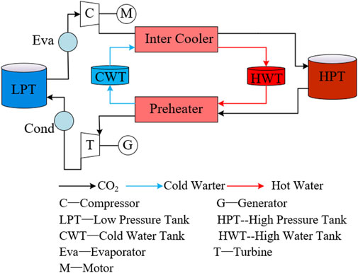
FIGURE 2. LCES schematic.
LCES consists of two working liquids, CO2 and water. The charging process can be summarized as evaporation, compression, and cooling. The liquid CO2 stored in the LPT (7.4 MPa, 30°C) is evaporated by absorbing heat in the evaporator (32°C). The low-pressure CO2 is then compressed to a high-pressure state by a compressor powered by renewable energy or electricity during low electric load periods. The compressed CO2 entered the intercooler and returned to the liquid state storage in the high-pressure tank. At the same time, the thermal compression is transferred to the water cycle in the hot water tank. Similar to the charging process, the discharging method comprises preheating, expansion and condensation. During peak electrical load hours, the high-pressure liquid CO2 in the HPT absorbs the heat of compression in the preheater. It then converts the pressure and heat energy in the CO2 into controlled mechanical work in the turbine. After expansion, the CO2 condenses into a liquid state using cooling water and is stored in the LPT.
The mathematical model for compressor and turbine operation in LCES.
Where,
The HWT in the LCES can be involved in storing heat and providing heat load, and the mathematical model of an LCES HWT is as follows:
Where
The CO2 pressure of the remaining gas in the HPT can reflect its remaining storage energy, and the relationship between the CO2 pressure of the HPT and the inlet and outlet mass flow rate is:
Where
Mathematical model of CCPP
In this paper, the CCPP operates in conjunction with WT and PV to provide electrical load. Part of the wind and photovoltaic power is supplied to the CCS; another part is used as a power supply for PtG, and the rest of the power is fed into the grid. A portion of the power generated by the CCPP is utilized as carbon capture energy to supply the CCS, and the rest of the power is fed into the grid. The mathematical model of a carbon capture power plant (Liu et al., 2019) is
Where
IES low carbon economic model
Objective function
In this paper, to minimize the total operating cost in the IES dispatch, the dispatch plan is prepared by solving for the optimal output of each unit. The objective function is.
Where
Where,
Constraints
IES operation is required to satisfy the operating balance constraints for electrical and thermal power:
Where
LCES operating state constraints:
Where,
The planning variables of the model in this paper include the LCES charging and discharging power at each moment, the issued power of each unit, and the natural gas market supply volume, and the constraints are mostly inequality constraints with upper and lower bounds. The IES day-ahead optimization scheduling model with LCES established in this paper is a mixed integer linear programming, which can be resolved by calling the CPLEX solver based on the YALMIP platform in MATLAB software.
Experimental verification
Test parameters
The experimental example model in this paper takes a small regional IES in northern China as the research object. Regarding its daily electricity load and heat load data, as shown in Figure 3, the predicted output of WT and PV is shown in Figure 4. The carbon trading price is 19.8 $/t, the natural gas transaction price is 0.42 $/m3, the dispatch period is 24 h, and the unit dispatch time is 1 hour. The LCES operating parameters (Wu et al., 2016; Wang et al., 2015) are shown in Table 1. The paper assumes that renewable energy is all consumed. Other system parameters in the IES system are shown in Table 2. Abbreviations and symbols used in the equations and mathematical formulations are shown in Table 3.
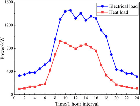
FIGURE 3. Electric and thermal load forecast values.
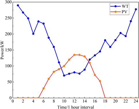
FIGURE 4. WT and PV forecast values.
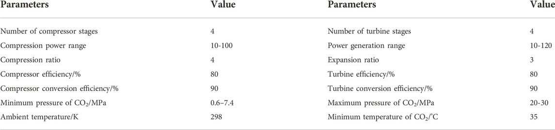
TABLE 1. Fixed value and Optimization variables of LCES.
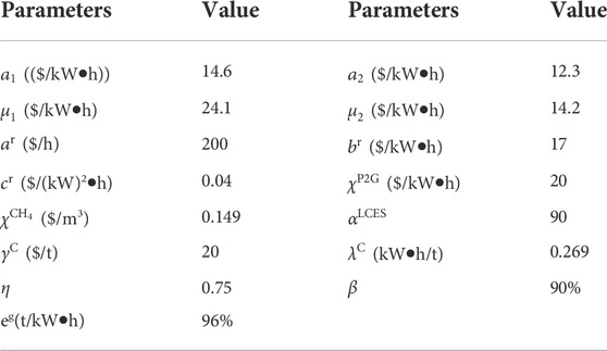
TABLE 2. Other system parameters in the IES system.
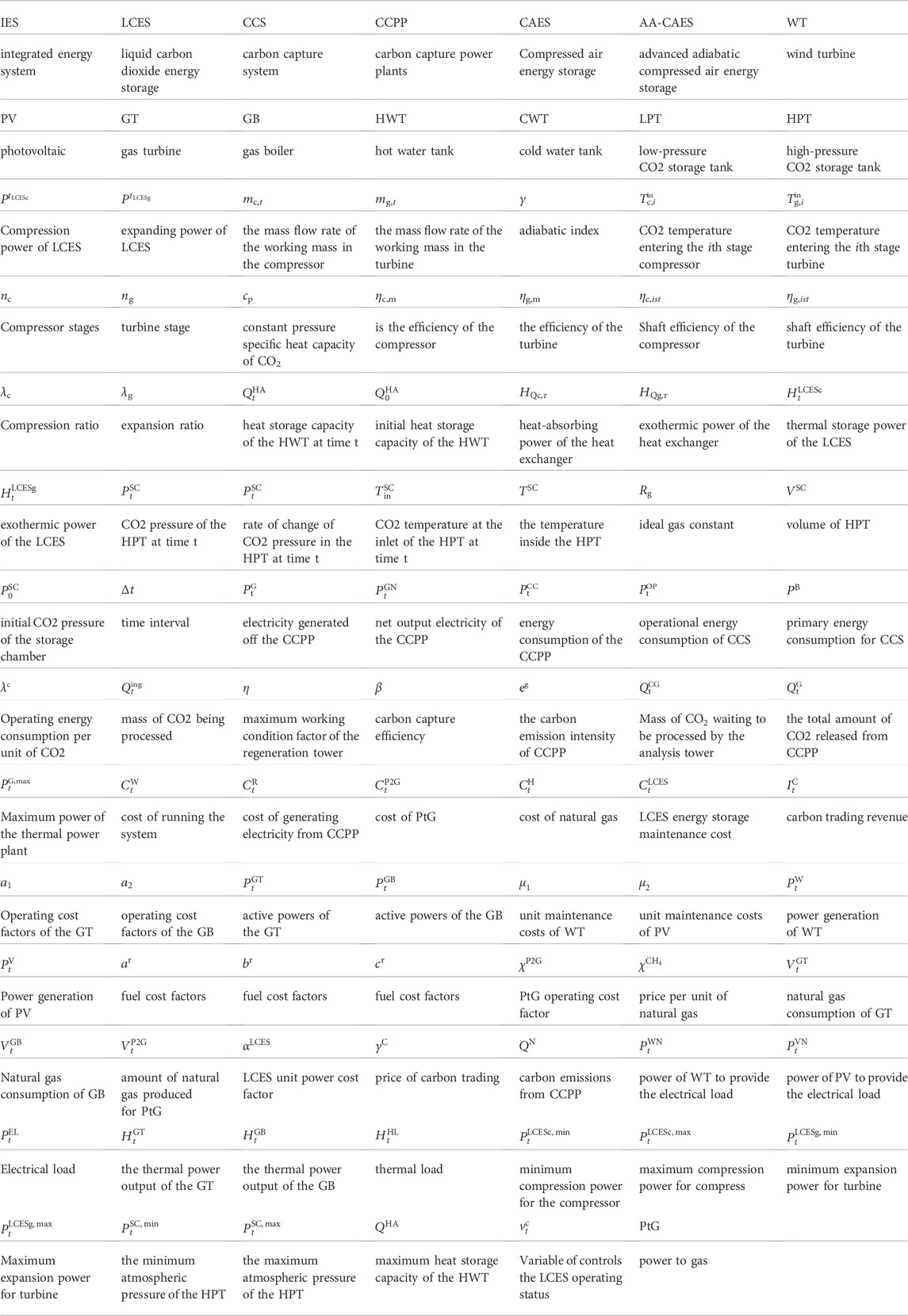
TABLE 3. Abbreviations and symbols used in the equations and mathematical formulations.
Results of analysis
This paper verifies the advantages of the LCES over the battery on the operational benefits of IES and the low carbon impact of CCS on IES. Four scenarios are set up in this paper for comparison.
Scenario one assumes that the IES contains battery energy storage without CCS.
Scenario two assumes that the IES contains battery energy storage and CCS.
Scenario three assumes that the IES contains LCES without CCS.
Scenario four assumes that IES contains LCES and CCS.
According to the four scenarios, each unit’s cost and revenue results and the dispatching situation results are optimized and obtained as shown in Tables 4, 5. Where, a negative carbon trading cost indicates that the system gains from the carbon trading mechanism, and conversely, a positive one pays a corresponding cost The comparative analysis shows the following:
1) Scenario two compared to Scenario 1, equipped with CCS, CO2 trading revenue increased by $1 664 and CO2 emissions decreased by 2 472 tons, while renewable energy and CCPP will provide carbon dioxide capture energy consumption, resulting in an increase in electricity generation and a corresponding increase in the cost of electricity generation, but the total cost of the two combined is reduced by $3,924. Similarly, scenario 4 has 3222 tons fewer carbon emissions and 3069 $ fewer total costs than scenario 3. Thus, it can be seen that introducing CCS into the IES can reduce CO2 emissions. At the same time, it achieves efficient use of internal resources and reduces the total costs.
2) Scenario three compared to scenario 1, the total costs are reduced by $1145. CO2 transactions in both scenarios show punitive costs and the same value, with the most obvious cost difference between the two scenarios being the CCPP cost. The combined electricity-thermal supply of the LCES will provide more power, reducing the CCPP and system operation costs, and the WT and PV with a high ratio of 220 kW feed-in power. Thus, LCES has the advantage of promoting renewable energy consumption and reducing the total system operation cost over the battery in the IES.
3) Scenario four compared to scenario 2, the renewable energy feed-in power increases, the CCPP output decreases, the cost reduces by $158, the PtG cost decreases by $59, and the total cost decreases by $291. At the same time, CO2 emissions are reduced by 474 tons, and CO2 trading revenue is increased by $48. It can be seen that equipping LCES and CCS in IES can not only reduce the total system operation cost but also significantly increase the renewable energy consumption rate. At the same time, it reduces the CO2 emissions of the system and realizes the low carbon operation of the IES.
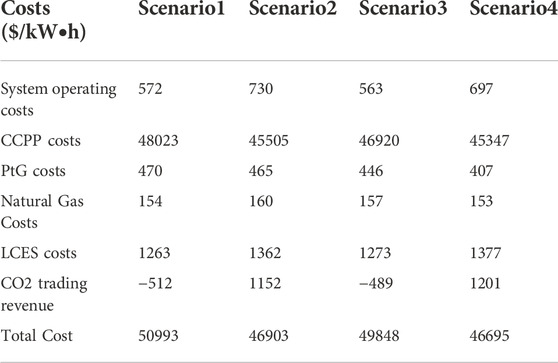
TABLE 4. Cost of IES in different scenarios ($/kW•h).
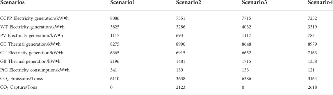
TABLE 5. The output of different units in each scenario.
The optimization results, the results obtained from Scenario four optimization, are shown in Figure 5 to Figure 8. According to Figure 5, it can be seen that the electric load is provided by CCPP, WT, PV, GT, and LCES. The electrical load is low from 22:00 to 4:00, and the producer uses surplus wind power for PtG to produce methane for the GT and GB while the remaining part of the power is stored in LCES. When the CCPP supply cannot meet the electric load during the peak load period, the LCES discharges energy to replenish the shortage.
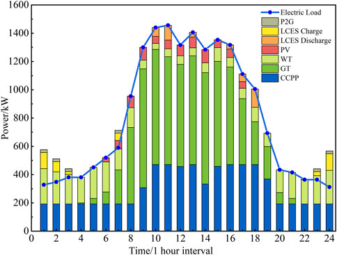
FIGURE 5. Electrical power balance.
Figure 6 demonstrates the output of each heating unit, and the GT, GB, and LCES supply the heat load. Because GT generates a large amount of waste heat in the process of providing power, the heat load is predominantly supplied by GT and assisted by GB during the peak period of 8:00-17:00. During the rest of the period, the heat load also requires the LCES to supply part of the heat.

FIGURE 6. Thermal power balance.
Figure 7 shows the system carbon trading results. CCS captures the CO2 generated in the carbon capture power plant and provides it to PtG to reduce CO2 emissions. During the period of 7:00-19:00, the electric load is higher, and the electric load is mainly supplied by the carbon capture plant, which generates more CO2. Meanwhile, as renewable energy output increases, some of the electricity will be provided to the CO2 capture plant, making the carbon capture plant capture more CO2 and increasing CO2 trading revenue.
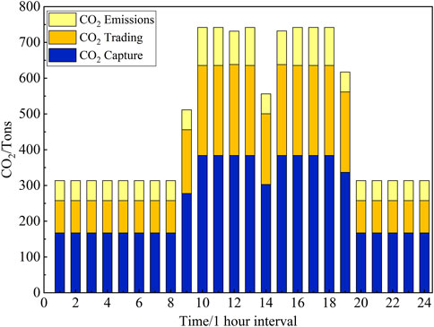
FIGURE 7. CO2 capture and emissions.
Figure 8 displays the charging and discharging of the energy of LCES with the variation of HPT air pressure. LCES can operate within its regular operation interval using the optimized model in this paper.
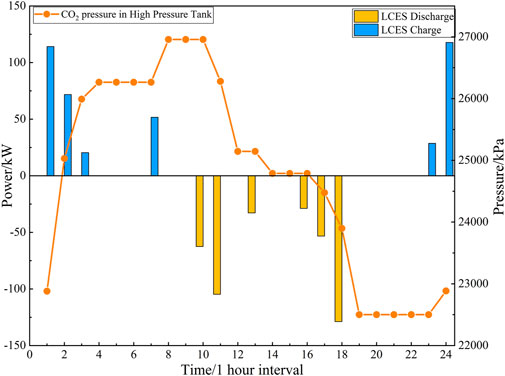
FIGURE 8. LCES charging and discharging power and HPT air pressure state.
Figure 9 shows the curve of CO2 trading benefits and emissions with the CO2 trading price. When the price of CO2 is 0, the CO2 trading cost of IES is 0. When the trading price is low, the system’s CO2 emissions are higher than the CO2 emission allowances. As the price increases, the CO2 trading revenue (which starts to be expressed as trading penalties slowly increases. Trading revenues begin to fall when the price exceeds $10 per ton. During this time, emissions remain above emission allowances, and the system still has to pay the cost of the CO2 trading penalty. When the price is $15 per ton, the emission decreases to an amount equal to the CCPP emission allowance. The CO2 trading revenue of the IES drops to 0, and after that, as the price increases, it starts to gain trading revenue (as a negative value); when the price exceeds $22 per ton, the emission remains unchanged, and the decreasing trend of trading gain is slow.
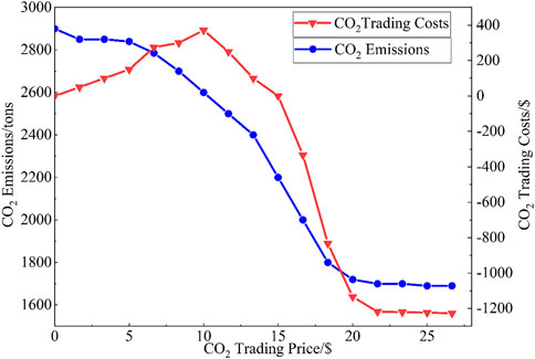
FIGURE 9. CO2 trading price uncertainty analysis.
Conclusion
This paper proposes an optimized scheduling model for an integrated energy system. The integrated energy system with liquid carbon dioxide energy storage combines the operation of four output units of WT, PV, CCPP, and LCES to realize the optimized electricity-heat scheduling and carbon reuse, making the internal resources more effectively used. The following conclusions are made through a comparative analysis of the scheduling results.
(1) heat-electricity multi-energy supply, which can effectively reduce the operation cost of the IES and improve the energy utilization efficiency of IES after participating in the optimized operation of the integrated energy system.
(2) CO2 capture equipment can gain CO2 trading revenue by participating in the operation of IES. At the same time, it improves the utilization rate of renewable energy, which verifies the economy and low carbon of CO2 capture equipment.
(3) The integrated energy system scheduling model is sensitive to changes in the CO2 trading price and can coordinate the CO2 emission situation and system cost by setting the appropriate CO2 trading price.
Data availability statement
The original contributions presented in the study are included in the article/supplementary material, further inquiries can be directed to the corresponding author.
Author contributions
JZ contributed to the model, simulation and writing. JC contributed to the method. HS and XJ contributed equally to the editing of the article and discussion. JC contributed to the literature analysis and provided a critical review. JL contributed to paper's review and grammar revision.
Conflict of interest
The authors declare that the research was conducted in the absence of any commercial or financial relationships that could be construed as a potential conflict of interest.
Publisher’s note
All claims expressed in this article are solely those of the authors and do not necessarily represent those of their affiliated organizations, or those of the publisher, the editors and the reviewers. Any product that may be evaluated in this article, or claim that may be made by its manufacturer, is not guaranteed or endorsed by the publisher.
References
Fu, Z., Li, B., and Wang, H. (2022). Real-time optimal scheduling of multi-microgrids considering renewable energy intermittency. Front. Energy Res. 10. doi:10.3389/fenrg.2022.888156
Han, Z., Sun, Ye, Peng, Li, and Hu, Qy. (2022) Study on the operation of compressed air/carbon dioxide energy storage system. J. Sol. Energy 43 (3), 119.
He, Q., Chen, H., Lin, Z., Dai, X., Huang, Y., and Cai, W. (2022). A cost-based life-cycle pricing model for offshore wind power plants within China's carbon trading scheme. Energy Rep. 8, 147. doi:10.1016/j.egyr.2022.08.101
Li, Y., Li, O., Wu, F., Shi, L., Ma, S., and Zhou, B. (2022). Coordinated multi-objective capacity optimization of wind-photovoltaic-pumped storage hybrid system. Energy Rep. 8, 1303. doi:10.1016/j.egyr.2022.08.160
Li, Y. P., Xu, Y. J., Li, B., Guo, H, Guo, C, and Chen, H. S. (2018). Research on trans-critical carbon dioxide energy storage system. Chin. J. Electr. Eng. 38(21), 6367–6374.
Liao, P., Wu, X., and Wang, M. (2022). Intelligent scheduling and flexible operation for the commercial-scale coal-fired power plant integrated with post-combustion carbon capture. IFAC-PapersOnLine 55(9) 553. doi:10.1016/j.ifacol.2022.07.096
Liu, S., Li, H., Zhang, K., and Lau, H. C. (2022). Techno-economic analysis of using carbon capture and storage (CCS) in decarbonizing China's coal-fired power plants. J. Clean. Prod. 351, 131384. doi:10.1016/j.jclepro.2022.131384
Liu, Z., Cao, F., Guo, J., Liu, J., Zhai, H., and Duan, Z. (2019). Performance analysis of a novel combined cooling, heating, and power system based on carbon dioxide energy storage. Energy Convers. Manag. 188, 151. doi:10.1016/j.enconman.2019.03.031
Ouyang, T., Xie, S., Pan, M., and Qin, P. (2022). Peak-shaving scheme for coal-fired power plant integrating flexible carbon capture and wastewater treatment. Energy Convers. Manag. 256, 115377. doi:10.1016/j.enconman.2022.115377
Paltsev, S., Morris, J., Kheshgi, H., and Herzog, H. (2021). Hard-to-Abate Sectors: The role of industrial carbon capture and storage (CCS) in emission mitigation. Appl. Energy 300, 117322. doi:10.1016/j.apenergy.2021.117322
Qiu, S., Chen, J., Mao, C., Duan, Q., Ma, C., Liu, Z., et al. (2022). Day-ahead optimal scheduling of power–gas–heating integrated energy system considering energy routing. Energy Rep. 8, 1113. doi:10.1016/j.egyr.2022.08.147
Shen, H., Zhang, H., Xu, Y., Chen, H., Zhu, Y., Zhang, Z., et al. (2022). Multi-objective capacity configuration optimization of an integrated energy system considering economy and environment with harvest heat. Energy Convers. Manag. 269. 116116, doi:10.1016/j.enconman.2022.116116
Shi, B., Li, N., Gao, Q., and Li, G. (2022). Market incentives, carbon quota allocation and carbon emission reduction: Evidence from China's carbon trading pilot policy. J. Environ. Manag. 319, 115650. doi:10.1016/j.jenvman.2022.115650
Wang, M., Zhao, P., Wu, Y., and Dai, Y. (2015). Performance analysis of a novel energy storage system based on liquid carbon dioxide. Appl. Therm. Eng. 91, 812. doi:10.1016/j.applthermaleng.2015.08.081
Wouters, C., Fraga, E. S., and James, A. M. (2015). An energy integrated, multi-microgrid, MILP (mixed-integer linear programming) approach for residential distributed energy system planning–a South Australian case study. Energy 85, 30, doi:10.1016/j.energy.2015.03.051
Wu, M., Du, P., Jiang, M., Goh, H H., Zhu, H., Zhang, D., et al. (2022). An integrated energy system optimization strategy based on particle swarm optimization algorithm, Energy Rep. 8, 679. doi:10.1016/j.egyr.2022.10.034
Wu, Y., Hu, D-S., Wang, M-K., and Dai, Y-P. (2016). A novel trans-critical CO_2 energy storage system. J. Xi'an Jiaot. Univ. 50 (3), 45–49.
Xi, H., Zhu, M., Lee, K. Y., and Wu, X. (2023). Multi-timescale and control-perceptive scheduling approach for flexible operation of power plant-carbon capture system. Fuel 331, 125695. doi:10.1016/j.fuel.2022.125695
Xu, M., Zhao, P., Huo, Y., Han, J., Wang, J., and Dai, Y. (2020). Thermodynamic analysis of a novel liquid carbon dioxide energy storage system and comparison to a liquid air energy storage system. J. Clean. Prod. 242, 118437. doi:10.1016/j.jclepro.2019.118437
Yan, N., Ma, G., Li, X., Qu, C., and Zhong, Y. (2022). Multi-stakeholders energy management and control method of integrated energy system considering carbon trading mechanism. Energy Rep. 8, 1090, doi:10.1016/j.egyr.2022.08.165
Yang, L, Wang, C, Li, G, Wang, J, Zhao, D, and Chen, C.(2020). Improving operational flexibility of integrated energy system with uncertain renewable generations considering thermal inertia of buildings. Energy Convers. Manag. 207, 112526. doi:10.1016/j.enconman.2020.112526
Yu, H., Engelkemier, S., and Gençer, E. (2022). Process improvements and multi-objective optimization of compressed air energy storage (CAES) system. J. Clean. Prod. 335, 130081. doi:10.1016/j.jclepro.2021.130081
Yuan, H., Ye, H., Chen, Y., and Deng, W. (2022). Research on the optimal configuration of photovoltaic and energy storage in rural microgrid. Energy Rep. 8, 1285. doi:10.1016/j.egyr.2022.08.115
Keywords: integrated energy system, liquid carbon dioxide energy storage, carbon capture system (CCS), renewable energy (RE), dispatch
Citation: Zhang J, Chen J, Ji X, Sun H and Liu J (2023) Low-carbon economic dispatch of integrated energy system based on liquid carbon dioxide energy storage. Front. Energy Res. 10:1051630. doi: 10.3389/fenrg.2022.1051630
Received: 23 September 2022; Accepted: 16 November 2022;
Published: 17 January 2023.
Edited by:
Harun Or Rashid Howlader, University of the Ryukyus, JapanReviewed by:
Abdul Motin Howlader, California Air Resources Board, United StatesOludamilare Adewuyi, First Technical University, Nigeria
Copyright © 2023 Zhang, Chen, Ji, Sun and Liu. This is an open-access article distributed under the terms of the Creative Commons Attribution License (CC BY). The use, distribution or reproduction in other forums is permitted, provided the original author(s) and the copyright owner(s) are credited and that the original publication in this journal is cited, in accordance with accepted academic practice. No use, distribution or reproduction is permitted which does not comply with these terms.
*Correspondence: Jie Chen, eGpfY2pAMTYzLmNvbQ==