 Shadrack Adjei Takyi
 Yindi Zhang
 Mengting Si1
 Yingnan Li
94% of researchers rate our articles as excellent or good
Learn more about the work of our research integrity team to safeguard the quality of each article we publish.
Find out more
REVIEW article
Front. Energy Res., 06 January 2023
Sec. Carbon Capture, Utilization and Storage
Volume 10 - 2022 | https://doi.org/10.3389/fenrg.2022.1051417
This article is part of the Research TopicReviews in Carbon Capture, Utilization and Storage: 2022View all 5 articles
Although coal mining has played a substantial role in world’s development as a critical fuel source for at least 25 years, its value is partly offset by the massive environmental issues it presents during combustion. The shift to a net-zero CO2 emission will open unique possibilities for new coal technological models in which progressive studies and policies, development, and modernization will play a significant role. Therefore, a collection of technologies has been proposed, one of which is cost-effective is the Underground Coal Gasification (UCG) coupled with carbon capture storage (CCS) and utilization technology (CCU) UCG-CCS/CCU. This paper reviews the current status and technology development in implementing low carbon emission energy on underground coal gasification. The study, therefore, leads to discussing the modern stage of underground coal gasification and carbon capture storage development, recent pilot operations, and current developments of the growing market. At the same time, it provides a reference for underground coal gasification combined with CCUS technology.
Coal is presently an essential energy source throughout the world, except for the middle east and the Former Union of Soviet Socialist Republics (USSR), which have virtually two-thirds or more of the global oil and natural gas reserves (Grimston, 1999) and will remain for many ages (EIA and International, 2003; Miller, 2005). reports a detailed estimate of coal reserves and producing nations for major states worldwide. Research by EIA (2003) also estimates energy production and consumption primarily by regions and countries. Research by EIA and International (2002) gives a projected world coal consumption by region for a forecast period to 2020. It is therefore observed that by 2030, future world coal consumption is expected to increase in regions like China, the United States, India, Non-OECD Asia, Japan, Russia, and others (Non-OECD Europe and Eurasia, ex Russia) (Department of Energy EIA Energy Information Administration, 2009).
Although coal has played a substantial role in world development as an essential fuel source for at least the subsequent quarter-century, its value is partly offset by the massive environmental issues it presents during combustion. According to IEA (2009), CO2 discharges worldwide raised from 1.7% in 2018 to a significant height of 33.1 GtCO2. This was the maximum growth rate since 2013 and 70% more than the average increase since 2010. Coal accounts for more than 70% of fuel’s total energy-related CO2 emissions (The World bank, 2014). Overall, global coal burning is accountable for 46% of the emission of CO2 and further records for 72% of overall greenhouse gas releases from the electricity section. The common usage of coal evidence this in generating electrical power, and the extremely high CO2 intensity of coal-fired power. Coal emits significantly more CO2 emissions per unit of energy produced than oil and more than twice as much as natural gas. Annually, coal burning yields over 14 billion tons of atmospheric-released CO2, specifically from power generation. As reported by IEA (2009), coal consumption for power alone surpassed 10 GtCO2, mainly in Asia. China, India, and the United States recorded an 85% increase in net CO2 emissions, while regions like Germany, Japan, Mexico, France, and the United Kingdom accounted for decreased reductions. CO2 Earth (2017) states that by 2,100, the levels of atmospheric CO2 are estimated to reach about 800 ppm resulting in the rise of the earth’s surface temperature to about 4°C if no immediate and effective actions are taken. Concerning the latest accessible science and the necessity to uplift global climate action, the European Council recommends attaining a climate-neutral EU by 2050, per the aims of the Paris Agreement (EU, 2020). The shift to a net-zero CO2 emission will open unique possibilities for new technological models in which progressive research, growth, and modernization policies will have a crucial role. To achieve this aim, a collection of technologies has been projected, one of which is cost-effective (Nakaten et al., 2014) is the carbon capture (CC), utilization and storage technology (CCUS) (Dixon, 2016), coupled with Underground Coal Gasification (UCG-CCS/CCU.)
UCG is a coal technology characterized by a high resource utilization rate (Green, 2018). UCG provides both economic and enviro-friendly approaches to raising coal reserves by utilizing the un-mineable coal deposits by the conventional approach. According to Bhutto et al. (2013), UCG alters coal into gas, accompanied by eliminating sulfides and nitrogen oxides, evading the conventional coal-burning process, and has the features of minimum pollution emission, see Figure 1. UCG has numerous economic and environmental benefits (Blinderman and Anderson, 2003). The technology is much cheaper, eliminates land degradation and mining activity, and sharply permits a functioning UCG plant to increase its syngas production at minimal capital cost. UCG appears to be the leading appropriate technology to be deployed in combination with geological storing of CO2—geological settings promising for UCG are also promising for CO2 storing (Friedmann, 2006). Other applicable technologies can also join UCG to produce synthetic fuel and recover coal bed methane. The rising variability in the worldwide energy condition is bringing out shareholders in nations with primary coal deposits and present or coming energy shortfalls to recommence attention to all technologies with capabilities to raise the use of domestic coal resources (Burton et al., 2006). For virtually a century of global research and practice, many workshops, practices, and successes have been amassed in the approaches and technologies of UCG.
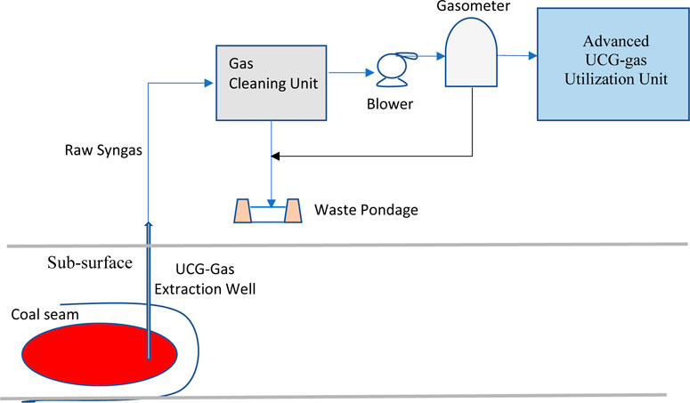
FIGURE 1. Schematic of UCG process with gas cleaning unit.
Since the 20th century, over 50 pilot-scale operations of UCG have taken place in Europe, Australia, China, the Former Union of Soviet Socialist Republics (USSR), the United States, and South Africa (see Tables 1, 2). These tests have mainly been commenced at low depths, as seen at the 140 m Chinchilla in Australia, Angren (110 m) in Uzbekistan, Hoe Creek (30–40 m) in the United States, and Hanna (80 m) also in the United States (Prabu and Jayanti, 2012). The USSR UCG program is believed to have used up 15 Mt of coal, and the US research effort to increase regulation and efficiency of the UCG development in about 60 separate tests is projected to have vaporized 100,000 tons of coal. However, it was halted shortly by the same minimum prices of natural gas in the 1990 s. From 1974 to 1989, scientific investigations and the expansion of UCG rose in the United States. Thirty-three pilot projects of UCG were planned and sited in Texas, Wyoming, Alabama, West Virginia, and Washington (Gem, 2021). Among them, the most effective was the Rocky Mountain 1 project in Carbon County, Wyoming (Clean Air Task Force Report, 2009). Many companies worldwide have initiated successful UCG projects that include electric generation and coal-to-liquids. In 2002 (Sasol, 2013), Eskom initiated its UCG technology development (using Ergo Energy’s UCG technology) and successfully piloted it for 5 years with proven results. The same technology has been utilized in three UCG projects in the past few years, particularly Linc Energy’s initial Chinchilla UCG project in Australia, the Huntly West UCG project in New Zealand established by Solid Energy, and Eskom’s Majuba pilot project in South Africa. The Ergo Energy’s UGC technology is utilized to expand commercialized UCG energy plans in Canada, China, the United States, New Zealand, India, and other nations. In 2006, under the sponsorships of the US-India Energy Dialogue Coal Working Group and the Asia Pacific Partnership, a UCG workshop took place in India Kolkata (US Department of Energy, 2006) and Houston (Burton et al., 2006) to accelerate the implementation of UCG and initiate a commercial UCG project set to deliver gas. Studies from esteemed economics have placed power production from UCG Levelized electricity rate at around €49 MWh in the absence of CCS and €72 MWh with CCS (Nakaten et al., 2014), which proposes that UCG is highly viable for power generation in both methods of operation. According to Eskom Holdings Ltd (2008), the Angren power station in Uzbekistan has generated power from UCG gas for over 50 years by co-firing the gas with coal in a boiler. Lately (DECC Report, 2015) puts the UCG power generation release of CO2 with combined cycle gas turbine (CCGT) in the range 570–785 kg CO2 MWh without resource to CCS, relative to natural gas at 400 kg CO2 MWh. CCS could decrease the emissions of UCG to 100 kg CO2 MWh less. These values are remarkable and therefore put UCG on equivalence to renewable energy sources and the finest fossil fuel discharges with CCS.
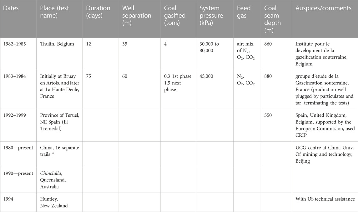
TABLE 1. International UCG pilots operations (Prabu and Jayanti, 2012).

TABLE 2. 20th century UCG primary projects.
UCG involves compound physical and chemical processes, and the composition and quality of the syngas are affected by many factors. Given the high-temperature humidity and closed setting, it becomes problematic to efficiently monitor and control the overall UCG process to upgrade the quality of the syngas. Studies by Mostade (2014) confirm that the technical challenge with UCG monitoring and controlling the hot cavity to move safely and reliably along the coal seam and convert as much coal as possible into valuable, sustainable, high-quality syngas. UCG is currently noted as a composite process where engineers are proficient in forecasting the accessibility and dependability of the entire process during the construction, process control, and monitoring of UCG operations together with the post-operation shutdown program (Mojibul and Mohammad, 2015). All UCG modules (the arrangement of both linked injection and production point) are identical. Thus, they require at least two process points connected within the coal seam to inject the vaporizing agents and begin ignition (injection point) and the other for recovering the syngas that is produced (production point) (Lavis et al., 2013). Between these two process points, a higher-performance gas circuit needs to be built by increasing the permeability of coal in a process called “linking.”
Therefore, scholars in many countries have conducted meaningful studies on UCG modules. According to (Mojibul and Mohammad, 2015), there are various methods, such as hydraulic fracturing, horizontal drilling, reverse combustion, linked vertical well (LVW), electric linkage, and controlled retractable injection point (CRIP) method. Another suitable technology based on the Former Union of Soviet Socialist Republics (USSR) UCG technology is Ergo Energy’s UCG technology (Burton et al., 2006). Other technology development modules are China’s Long Tunnel Method (Lavis et al., 2013), “Super Daisy Shaft,” and Single Well Flow Tube (SWIFT) technology. Portman Energy established SWIFT technology and uses a single vertical well for oxidant injection and syngas supply (Couch, 2009).
The Lawrence Livermore National Laboratory developed the CRIP method in the US in 1970 (Kumar, 2014). The production wells are drilled vertically, and the injection wells are drilled using directional drilling techniques to connect to the production wells. Once the channel is established, a burner attached to the retractable coiled tubing is used to initiate the gasification cavity, which ignites the coal as it burns the borehole casing (Hill, 1983). CRIP provides a stationary state of the vertical press-in well, but if necessary, the press-in point moves to fresh coal within the coal seam (Hill, 1983). Studies in Klimenko (2009) have confirmed that the flash point can be moved along the horizontal injection well to create a new gasification cavity when the coal near the cavity is exhausted. The second combustion begins near the injection well when the first combustion is finished. This way, the progress of gasification can be precisely controlled, and this procedure continues until the seams are burned out. Syngas, more than one-third of hydrogen in many early UCG pilots (the rest are CO2, CO, CH4, and higher hydrocarbons), is brought to the surface and processed to remove particles, CO2, and H2S. Moreover, CO is converted. From CH4 and higher hydrocarbons to more hydrogen (Burton et al., 2006). See Figures 2A, B.
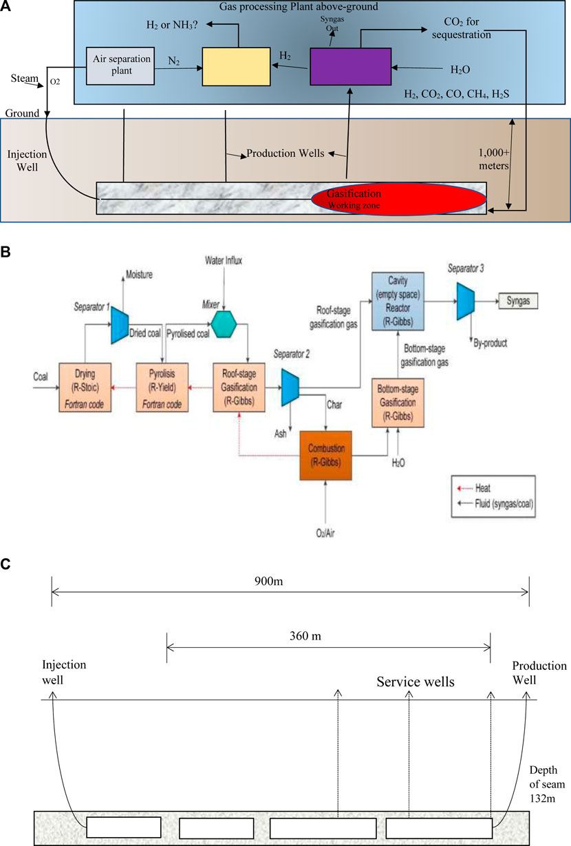
FIGURE 2. (A) Schematic of the CRIP process. (B) Chemical process model for simulating CRIP underground layout of (Burton et al., 2006). (C) Gasifier layout for linear CRIP configuration.
The concept of CRIP can be divided into Linear-CRIP (L-CRIP) (see Figure 2C) and Parallel-CRIP (P-CRIP) configurations. In the L-CRIP configuration, both process points are linked by one intra-seam excursion well. In a P-CRIP configuration, both process wells are drilled into the seam parallel to each other. See UGE (1999) and Nourozieh et al. (2010) for more information on the two processes.
The CRIP method was primarily developed in the US in the 1980 s during major R & D stages (Cena et al., 1988), in Spain (1990s), Australia (late 1990s to present), and currently in Alberta, Canada (from late 2000s to the present) (Lavis et al., 2013). The L-CRIP configuration has been successfully demonstrated at shallow depth (110 m) in the Rocky Mountain 1 (RM-1), Wyoming, US, at intermediate depth (500–600 m) in the European UCG project at El Tremedal, Teruel, Spain, and is currently being used to produce high-quality syngas at great depth (1,400 m) in the Swan Hills UCG project, Alberta, Canada (Hill and Shannon, 1981). In addition, the P-CRIP configuration was first tested at the partial seam CRIP test (Tono-1) in Centralia, Washington State, US, and has since been used during the RM-1 trial (Tono-2), United States, and by Carbon Energy and LINC at their respective facilities in Queensland, Australia (Mostade, 2014).
SHS(2012) states that the LVW method is one of UCG’s oldest methods and is derived from technology developed in the former Soviet Union. A vertical well is drilled at the coal seam and uses the coal’s internal pathways to direct the oxidizer flow and produced gas from the inlet to the exit borehole. Internal pathways can occur naturally or be constructed via reverse combustion, electrical coupling, and hydraulic fracturing (Shafirovich and Varma, 2009).
The injection point is located at the complete base of the vertical injection well, and the production point is at the complete base of the vertical production well (Mostade, 2014). In the simplest form, the entry and exit drilling positions of the LVW method are stationary throughout the life of the system. However, it has been found that as the coal surface moves during operation and the distance from the coal surface to the oxidant injection point increases, system control, performance, and syngas quality are adversely affected (Liang et al., 1999). This factor significantly decreases the viability of a simple LVW system. When the coal in the area is exhausted, a new hole will be drilled to replace the new coal, forming new zones. See Figures 3A, B.
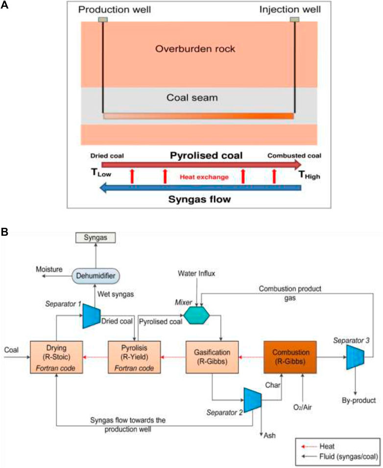
FIGURE 3. (A) Upright cross-section of underground LVW gasifier. (B) A chemical process model used to simulate the underground layout of LVW (Liang et al., 1999).
The Majuba UCG project has produced syngas and coal since January 2007 and the end of 2010. The project contributed approximately 3 MW of electricity to the total output of 650 MW. Currently, the project is the longest-running UCG test in the Western world. It is planned to expand the facility to an output of 1200 MW, and 30% of the plant’s fuel will be provided by syngas (Roddy and Younger, 2010).
LVW configurations have been used at Solid Energy’s facility at Huntly, New Zealand, as well as other locations in China and Canada (Laurus Energy). The LVW configuration was also used at Cougar Energy’s facility in Kingaroy, Australia (Mostade, 2014). Alternatives of the LVW method are continuously used today, especially at the UCG facility in Angren, Uzbekistan, which has the longest continuous operation in the world (Lavis et al., 2013).
Ergo Energy’s UCG is a proprietary process used by Ergo Exergy and may be based on the former Union of Soviet Socialist Republics (USSR) UCG technology. It relies on using the natural passages at the coal seams and strengthening them as needed to establish a connection between the press-in well and the production well. Ergo Energy’s UCG technology is practical and based on the practical experience of operating a commercial UCG factory. The design flexibility and multiple methods and technologies used by Ergo Exergy enable it to be applied to various coal qualities and grades (from lignite to bituminous coal) and geological environments (Burton et al., 2006).
It employs all currently available drilling methods, including precision directional wells and traditional vertical and sloping (tilted) wells. Its arsenal includes different ways to connect wells, different oxidant injections (air, O2/H2O.), and different underground vaporizer designs. It can be applied to coal under various geological and hydrogeological conditions. In each geological environment, the specific Ergo Energy’s UCG design is tailored to the specific conditions of the coal seam of interest (Power, 2011).
The Australian Chinchilla project has effectively established Ergo Energy’s UCG technology. In this project, a projected 35,000 tons of coal were used to produce 80,000,000 Nm3 of syngas at 5 MJ/Nm3. Ergo Energy’s UCG technology is also been reviewed for the projected Powder River Basin UCG project and in a cooperative project between Gas Authority India, Ltd. (GAIL) and Ergo Exergy.
The 1997 to 2006 Chinchilla I UCG project in Australia (350 km west of Brisbane, Queensland) was the first to establish Ergo Energy’s UCG as gas production technology (Maev et al., 2018). Ergo Exergy supplied the technology for the project and designed and operated the plant. In the past 16 years, the technology has been used in four syngas production projects as seen in the 1999 to 2006 Chinchilla project (Australia); 2007 to present Eskom (South Africa) project; Kingaroy (Australia), 2010; and the Huntly West (New Zealand), 2012 (Maev et al., 2018). A Conceptual design of Ergo Energy’s UCG IGCC plant is shown in Figure 4. Table 3 shows the coalfields where Ergo Energy’s UCG is used around the world (Power, 2011).
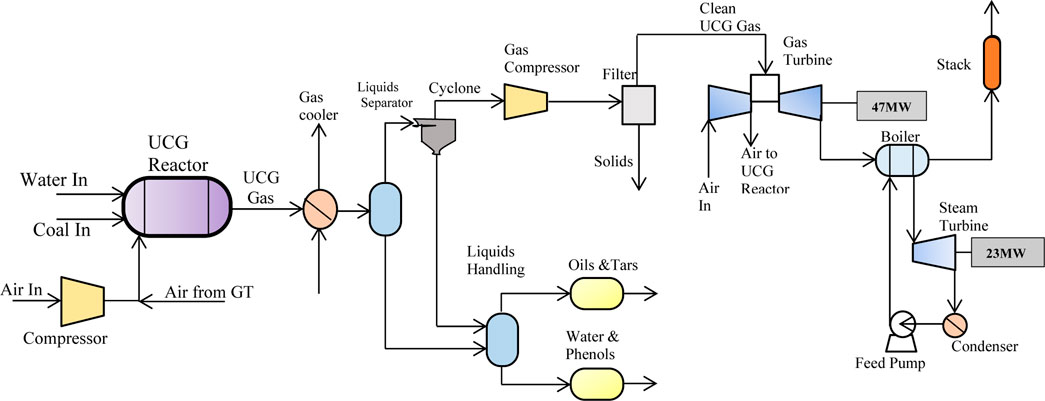
FIGURE 4. Conceptual design of the ergo energy UCG-IGCC plant.
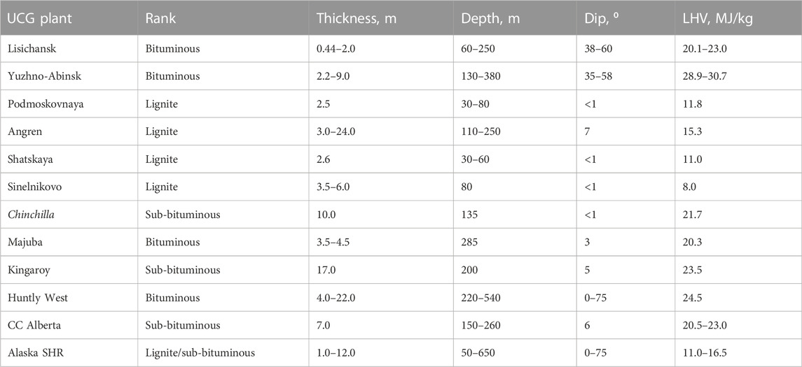
TABLE 3. Various ergo energy UCG technology projects.
Early UCG tests applied flow meters, thermocouples, and gas analyzers to monitor temperatures and combustion conditions from the underground (Blinderman and Jones, 2002). These measurements track underground combustion conditions and their corresponding subsidence but are effective for shallow coal seams and lower resolution for deep coal seams. However, in a hot and humid UCG setting, the accuracy of such sensors may be low and may not work properly. In addition Mellors et al. (2016) researched and designed a UCG monitoring system based on a self-organizing network of wireless sensors. However, the system has been tested in the laboratory, and the high temperature and high humidity environmental factors were not considered in the design. Wang et al. (2017) used Siemens S7-300 PLC and Fame View configuration software to develop a real-time monitoring system for UCG. However, the laboratory has tested the system, and the design does not consider the hot and humid environmental factors. Using the Siemens S7-300 PLC and Fame View configuration software, Wang et al. (2017) developed the UCG real-time monitoring system. However, the system is used for teaching experiments, and the design does not consider environmental factors such as high temperature and humidity (Guan et al., 2016) built a wireless sensor network and planned a UGS monitoring system to monitor groundwater pollution during gasification. However, its sensor components are inappropriate for the representative UCG high humidity and temperature setting. Barnwal et al. (2017) proposed a new method of producing coal with high moisture and low calorific value to improve the synthesis gas quality of UCG technology. However, these methods are expensive or temporarily not scalable. On the other hand Kostúr et al. (2015) created the UCG visualization information system to visualize the state of the UCG record. Based on this Nurzynska et al. (2014) monitors UCG data using GPR and visualizes them in 3D, see Figure 5. However, standard commercial radar systems are used to check the on-site and off-site coal combustion conditions. The results show that this method monitors and visualizes the coal gasification process under off-site combustion conditions. It is not suitable for other situations; that is, it is impossible to control the combustion state of coal in a real gasification process.
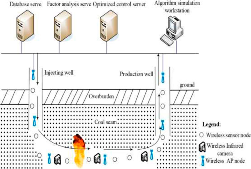
FIGURE 5. UCG monitoring system observation platform (Nurzynska et al., 2014).
UCG control is a developing area with few references to theoretical research and laboratory simulations. Kotyrba and Stanczyk. (2017) established and deduced the mathematical expression of gasified coal particles based on the theory of mass conservation, energy conservation, and chemical thermodynamics based on model tests. The calculated value is the same as the model test value. Some scientists have studied the combustion state of the gasifier based on mathematical models (Yang and Liu, 2010). These studies are effective in predicting the state of combustion. However, this is necessary in practice to accurately assess the combustion state in real-time (Khan et al., 2015) provides related properties that affect the combustion state of UCG through laboratory simulation experiments. The team then experimented to determine optimal operating conditions for syngas conversion and studied the effects of numerous operating parameters on changes in the gasified surface (Daggupati et al., 2010). However, a correct mathematical model was not provided to define these processes. Therefore Stanczyk et al. (2012) developed a one-dimensional numerical model to study the influence of operating conditions (for example, temperature, pressure, water flow, gas composition) and coal characteristics (for example, thermomechanical exfoliation characteristics, reactivity, composition) on the growth rate of local cavities and energy efficiency. It has been found that the thermal-mechanical cracking of coal, ash behavior, and the amount of carbon incorporated in the coal mainly affect the combustion rate (Perkins and Sahajwalla, 2006) projected a one-dimensional packed bed model for UCG control, which maintains the expected calorific value of the exhaust gas mixture by controlling the injected gas flow rate. The model can also predict important data parameters such as gas composition and combustion speed. However, in these control models, it is necessary to assume that the total concentration of all gases in the entire active chamber is constant. Uppal afterward improved the design of the simplified UCG model sliding mode control algorithm to ensure the stability of the thermal output value of the entire system (Uppal et al., 2014; Uppal et al., 2018; Saravanan et al., 2018).
For over 50 years, the Angren power station in Uzbekistan has been utilizing UCG to generate power by co-firing the gas with coal in a boiler (Marques et al., 2018). However, this method is based on old technology and does not realize all the advantages of UCG syngas power generation. Recently, many countries have proposed different UCG power generation projects as the next phase of UCG commercialization using modern technologies such as gas turbines (Linc Energy, 2015). Large-scale commercial UCG power plants are proposed to use combined cycle power plant technology due to their high thermal efficiency, low nitrogen oxide emissions, and low specific capital expenditures, see Table 4. The application of commercial syngas purification technology in the IGCC plant and Linc Energy’s Chinchilla GTL facility (see Figure 6) is expected to reduce air pollutant emissions from UCG power plants to levels similar to those of IGCC plants. Applying carbon dioxide capture and storage can further reduce carbon dioxide intensity to a level similar to natural gas power generation (Eskom Holdings Ltd, 2008). It is expected that in the next 10–15 years, coal power generation in most developed countries and China will decrease or stabilize, but many developing countries, especially Southern Africa, Southeast Asia, and India, are expected to expand the use of coal due to its low cost and abundant domestic supply is used for power generation (Gregg et al., 1976). However, it is well known that traditional coal-fired power generation has the highest levels of air pollutants and carbon emissions compared with other alternative energy sources such as natural gas or renewable energy. For decades, clean coal technologies such as IGCC have been developing to reduce the environmental impact of coal-fired power generation. IGCC technology has been successfully proven to produce extremely low air pollutant emissions, and the first plant using carbon capture is about to be completed (IEA, 2015). However, mainly due to high capital costs, the level of commercialization of IGCC has been low. There are significant opportunities to develop cost-effective clean coal technologies (such as UCG) as an alternative to traditional coal-fired power generation, especially for developing countries. By avoiding coal mining and surface gasification, UCG power generation has the potential to provide environmental performance similar to IGCC technology at a lower cost.

TABLE 4. 21st century UCG power projects (Linc Energy, 2015).
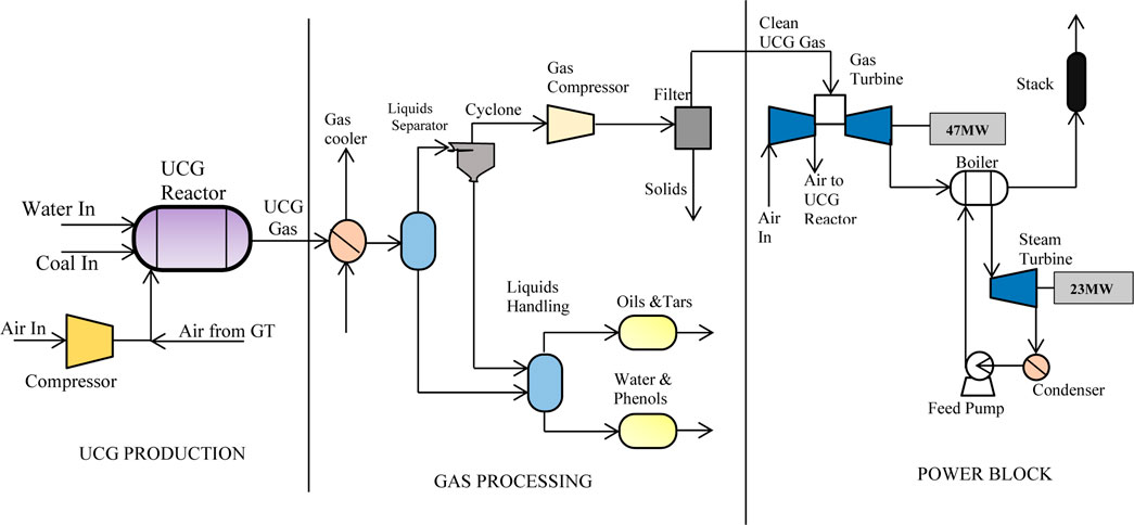
FIGURE 6. Conceptual design of the chinchilla project.
The UCG process occurs at relatively low temperatures compared to surface gases, and its properties are similar to a low-temperature fixed bed gas, such as a Lurgi FBDB gasifier (DOE/NETL, 2015a). Compared with high-temperature gasifiers, low-temperature gasifiers generally have higher cooling efficiency, lower oxygen demand, and can produce more hydrocarbon products (Thorsness and Britten, 1989). All modern IGCC plants are based on medium-temperature or high-temperature gasification technology. Compared with UCG-based plants, there are several key differences in gas purification and performance. Typical examples of IGCC plants that have recently adopted medium and high-temperature gasification include Kemper County (TRIG vaporizer), Buggenum (Shell vaporizer), and Edwardsport (GE vaporizer) (DOE/NETL Dennis, 2006). The advantage of medium-high temperature gasification is that synthesis gas composition is simpler, and the content of higher hydrocarbons and tar components is lower. The disadvantage is that high-temperature gasification requires a large amount of oxygen supply, and in order to achieve high thermal efficiency, heat recovery downstream of the gasifier under harsh conditions (DOE/NETL, 2015b). The UCG power generation process is similar to the surface-based IGCC, in which the UCG process replaces the coal mining process, surface gasification islands, and ash treatment plants. The air separation unit (ASU) supplies oxygen to the underground gasifier and produces crude syngas. The raw syngas is cooled and purified before being sent to the combined cycle gas turbine. The water separated from the gas is processed and reused, and the liquid hydrocarbon by-product (coal condensate) can be processed for sale or used as supplementary fuel. See Figure 7 for a Schematic of the UCG-IGCC 200 MW power plant.
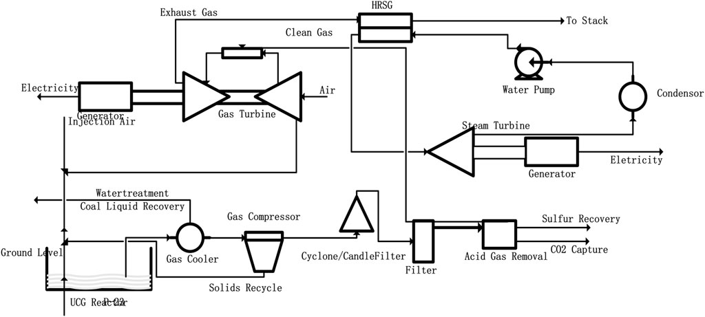
FIGURE 7. Schematic of UCG-IGCC 200 MW power plant (DOE/NETL, 2015b).
A robust interaction exists between UCG and the sequestration of carbon. Often, the high temperature and high pressure from the UCG syngas stream can significantly save the cost of carbon recovery and separation. In addition, as stated previously, the cavity formed in the UCG process can be used to store supercritical carbon dioxide. In either case, adjacent rocks may contain depleted oil and gas fields suitable for salinity (non-drinkable aquifers) or carbon dioxide storage (Burton et al., 2006). Figure 8 is a cost-determining practical and financial model for the comprehensive UCG and CCS/CCU scenario with reference from (Higman and van der Burgt, 2008).
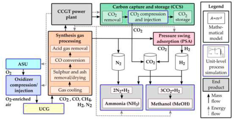
FIGURE 8. Technical and economic model for determining the cost of UCG, CCS and CCU.
CCS technologies can be implemented using various methods: post-combustion (PCC), pre-combustion, and oxyfuel capture (Nakaten et al., 2014). All of these technologies are currently in commercial demonstration, except chemical cycle combustion technologies, which are still in development (Wang et al., 2011).
When considering the potential to capture CO2 from UCG, it is important to understand the carbon distribution between gas composition and gas species. For deeper coal with greater pressure, it is well known that methane formation will increase (APEC, 2019). The carbon contained in methane can only be captured by reforming the gas, applying oxy-fuel combustion, or using post-combustion capture. Other ongoing developments aim to embrace CO2 sequestration in the voids from which coal has been extracted (Synfuels, 2012). CO2 capture occurs at high pressure in front of the combustion plant and is separated and stored using the same drilling and completion techniques as UCG. Even at depths of 1,000 m and above, it operates at the same pressure required for the high-density storage stage of CO2. The synergistic effect would be even greater if the same process in the gasification well could be modified and reused for storage.
Therefore, if a series of wells are open in the UCG chamber to produce syngas, the CO2 content is separated and reinjected from the abandoned well into a suitable underground structure for permanent storage. Fuel is efficiently produced for use in a combined cycle or fuel cell gas turbines, resulting in zero emissions for hydrogen and near-zero emissions for hydrogen-methane mixtures (The Trades Union Congress, 2014). Underground storage of CO2 can meet all minimum standards for leakage prevention. Therefore, it can be proved that the deep well UCG can be reused, regardless of whether it has been modified or not, it can be used for CO2 injection and permanent storage. Storage targets can also be placed in coal seams, upper layers, or abandoned UCG cavities. Primary estimations specify that at depths above 1,500 m, all CO2 produced by coal can be recovered (The Trades Union Congress, 2014).
It is necessary to separate and concentrate CO2 with a purity greater than 95% for injection. Most UCG applications yield a CO2 by-product stream of this purity level appropriate for GCS. For power generation, the Selexol or Rectisol process can be used to separate CO2 from the pre-combustion of syngas at a comparatively low cost of about $0.01 kWh. This will enable the carbon footprint of traditional NGCC facilities to generate electricity from UCG syngas (Burton et al., 2006). The syngas flow reaches the surface under severe pressure for deep UCG operations of depths greater than 600 m. For certain marketable applications (such as methanol and DME formulations), pressure can be used to reduce operating costs and energy loss. Equally, some CO2 capture technologies deliver well at high pressures (such as fluorinated solvents and Nexant’s CO2 hydrate process). These methods can further reduce the cost of capture and isolation. But, not all of these methods have been tested on a bulky profitable scale and need additional analysis before to deployment (Burton et al., 2006).
Pre-combustion CO2 capture is largely employed in IGCC and coal gasification-based polygeneration systems. IGCC and CCS/CCUS are currently one of the most promising directions. In the pre-combustion capture process, the fuel is changed into synthesis gas in the reformer or gasifier and then undergoes a shift reaction to yield a mixture of CO2 and H2. CO2 is mainly captured from this gas blend containing H2 at high pressure of 10–80 bar and moderate CO2 content of 15%–40%. In addition to CO2/H2 separation, the gas supply also contains CO, H2S, and, other sulfur components. The high pressure of this generated gas stream promotes the removal of CO2. The main CO2 removal technology is the absorption process, and the solvent can be a chemical or physical solvent. Removing u sulfur components, such as H2S, is also necessary from the gas stream (European Technology, 2005). See Figure 9.
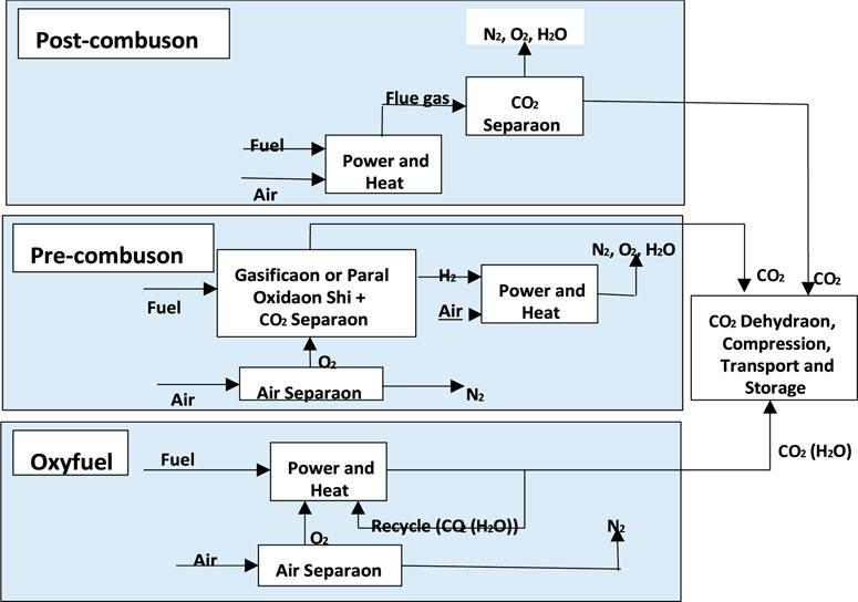
FIGURE 9. Carbon capture approaches and technology options (Tollefson, 2011).
The Project GreenGen, introduced by CHNG, is China’s foremost IGCC power plant. GreenGen in Tianjin develops, demonstrates, and promotes power plants with near-zero emissions, improves the efficiency of coal-fired power generation, and emits pollutants (sulfur dioxide, nitrogen oxides, particulate matter) and carbon dioxide. The project is grouped into three phases. The first phase is constructing a 250 MW level IGCC demonstration plant and the Greengen lab with a CO2 capture capacity of 30,000 tons/year. The second phase is the main IGCC technology and coal chemistry R&D (such as SNG and fuel cell application). The final phase involves the construction of a 400 MW IGCC demonstration power plant to capture and store 60% of carbon dioxide. According to the project’s first phase, a 250 MW IGCC power plant was constructed and passed the full trial operation on 6 November 2012 (European Technology, 2005).
PCC CO2 capture removes CO2 in flue gas discharged after combustion. Many first-generation CCS projects are expected to be implemented through PCC based on chemical absorption (Nakaten et al., 2014), as seen in Figure 10. Amine-based post-combustion capture is the most developed of the CO2 capture options. PCC CO2 recovery after combustion can remove CO2 in the flue gas emitted. As shown in Figure 10, numerous first-generation CCS developments are projected to be carried out through PCC connected with chemical absorption (Nakaten et al., 2014). Currently, the utmost advanced CO2 capture selection is the amine-based PCC.
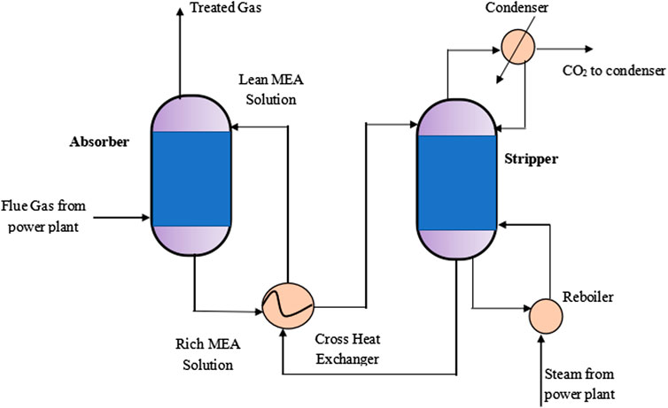
FIGURE 10. PCC based chemical absorption process.
In July 2008, the China Huaneng Group (CHNG) planned and manufactured the first capture test equipment for PCC CO2. The PCC system’s capture capacity for CO2 is 3,000 to 5,000 tons per year (Jinyi and Shisen, 2014). A year later, an annual CO2 capture demonstration device of 120,000 tons was completed in Shanghai and started operation in December 2009 (Tollefson, 2008). The first commercial-scale recovery power plant for PCC in the world is the Canada Boundary Dam Unit 3. It went into operation in 2014 and can recover 1 million tons of CO2 annually (Wang et al., 2011). Chemical absorption-based PCC developments using traditional amino solvents are currently at different technological levels. See Table 5 for commercial PCC based on the chemical absorption process.

TABLE 5. Chemical absorption-based PCC processes (Wang et al., 2011).
Combustion enhancement, characterized by oxy-fuel combustion, has been effectively applied in minor pilot projects. For example, the Schwarze Pumpe (30 MW) in Germany, Callide (30 MW) in Australia, and the 35 MW oxy-combustion test unit in Yingcheng, Huazhong University of Science are successful applications (Tollefson, 2011). See Figure 9.
Captured CO2 is typically pumped into deep saline and undeveloped deep coal or oil and gas-depleted fields (see Figure 11). Recently developed CO2 utilization technologies include chemical, geological, and bio utilization (Wang et al., 2011). However, traditional storage operations such as in brine formations and oil and gas fields are well known. These technologies are not expected to pose additional risks to the operation of UCG and should be considered the initial project development target. In contrast, storage in non-traditional units (oil shale, basalt) requires more scientific knowledge than is currently available (Burton et al., 2006).
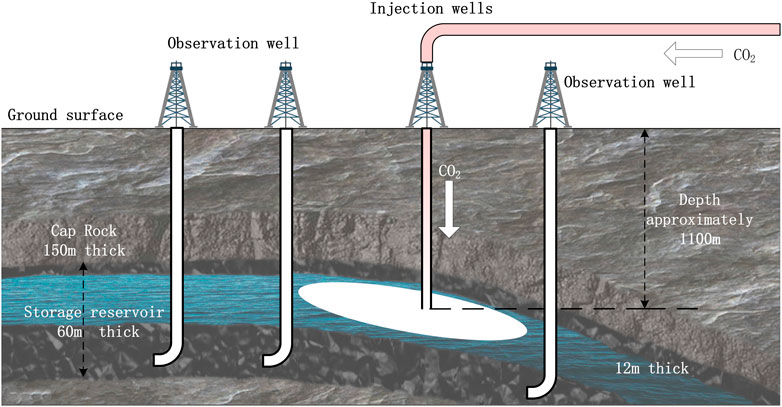
FIGURE 11. Cross-sectional diagram of underground CO2 storage (Wang et al., 2011).
CO2 transport methods primarily include tankers, vessels, and pipelines, and transporting CO2 over pipelines is considered the most cost-effective and consistent method for bulk and long-distance transport (Wang et al., 2011). Figure 12 shows a schematic flowchart of CCS and transportation.
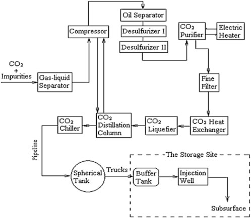
FIGURE 12. Schematic diagram of CO2 capture, storage and transportation (Tollefson, 2011).
Daggupati et al. (2011) and IEA (2016) carried out research scale UCG tests utilizing superheated steam as a gasifying medium. The advent of steam at a low temperature of 150°C to UCG combustion depth quenches the fire front and leads to unproductive gasification (IEA, 2016). Especially in the light of high ash Indian coals, steam dissemination through an ash deposit within the cavity may decrease the temperature. Furthermore, superheated steam transportation to deep underground cavities (>300 m) is challenging due to heat loss via pipelines. The linings of the pipelines result in extensive energy demand in the steam-based UCG process. Thus, according to (Stanczyk et al., 2012), UCG oxygen gasification is deliberate for coals with excessive ash content, and research shows the viability of creating a medium calorific product gas with enhanced CO (∼210 kJ/mol) in the absence of steam to the UCG input stream.
In UCG oxygen gasification, the integral moisture reactivity with char enhances the steam gasification reaction at the early stages of combustion; in any case, combustion-generated CO2 improves the Boudouard equation (Eq. 1) by reacting it with the adjoining char sites at the moisture depleted conditions of the coal seam.
Boudouard equation:
Therefore, research results from (Stanczyk et al., 2012) show high UCG practicability to be carried out in a CO2 mode, which is a promptly accessible enhancer for gasification. In addition Prabu and Jayanti (2012), examined Indian coal inherent gasification kinetic parameters in the temperature range of 800–1,050°C given CO2 based UCG with a thermogravimetric analyzer (Mandapati et al., 2012) experimented on O2/CO2 UCG gasification with different CO2 concentrations in a virtual coal seam. It was observed that CO2 UCG gasification increases the CO/H2 product gas ratio and improves gas calorific content. For proficient gasification, preheating the CO2 as a gasifying medium to high temperatures is cost-effective relative to the generation of superheated steam in a UCG steam-based operation. Furthermore, CO2 gas can be delivered at room temperature to the profound underground cavities for in-situ gasification.
Several works of literature have outlined ongoing research that uses CO2 gas as a key coal gasifying agent (Chen et al., 2013) carried out two-stage underground coal gasification using CO2 air as the gasifying medium. It was observed that with a rise in the CO2/oxidant molar ratio, the calorific content of the syngas reduced progressively. At 0.5 M proportion of CO2/oxidant, a syngas with a least standard calorific value of 65 kJ/mol is delivered. Figure 12 shows the calorific value of the product gas for the experiment in (Chen et al., 2013). Thus, it was established that the ideal stream rate of CO2 is 0.2 LPM for the O2/air molar proportion of 0.11 for coals with low ash. However, relative to high ash coals, the rise in the CO2 stream rate to 0.3 LPM led to quenching within the borehole combustion front. In this way, 0.2 is the ideal molar ratio of CO2/oxidant for high ash coals at the O2/air molar ratio of 1.
At present, economies such as the United States, Norway, Australia, France, and China have all carried out CCS demonstration projects, some of which have reached the commercial scale. By October 2017, there were 37 large CCS/CCUS integration projects (Daggupati et al., 2011) (each with a capture capacity of over 400,000 tons/year). Among them, 17 large-scale projects are in operation with a total CO2 capture capacity of 30 million tons/year: 10 EOR projects in North America, two saline formation storage projects in Norway, 1 EOR project in Brazil, 2 EOR projects in the Middle East and two saline formation storage projects in North America. CCS/CCUS is also developing rapidly in China, with several commercial demonstration projects successfully carried out (Wang et al., 2011). See Table 6.
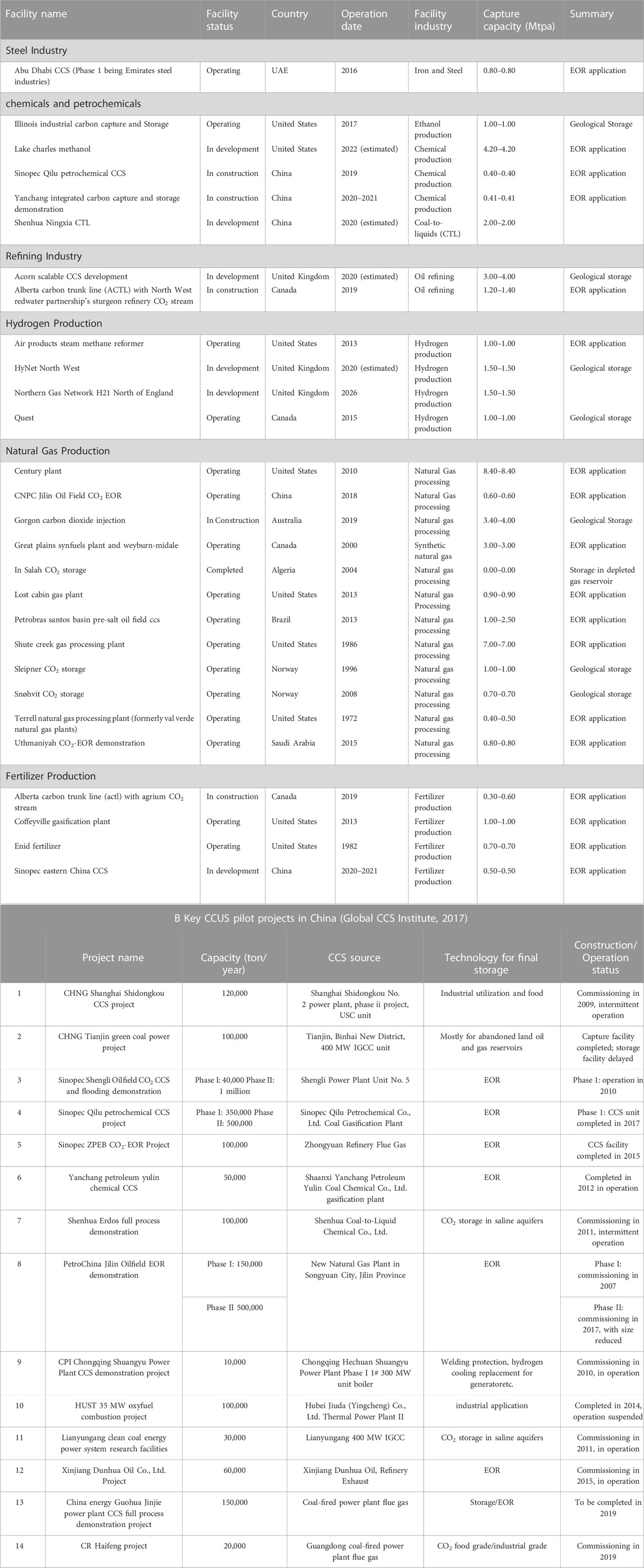
TABLE 6. A. Industrial CCS large-scale projects (>0.4 Mt/yr) (Wang et al., 2011).
Major economies have implemented CCS demonstration projects and gained commercial scale. These are evidenced in Australia, the US France, Norway, and China. There were 37 large-scale CCS/CCUS integrated projects, each having a recycling capacity of more than 400,000 tons/year as of October 2017 (Geeta and Prabu, 2017). Seventeen of them operate with an overall CO2 capture capacity of 30 million tons/year. In North America, there are 10 EOR projects and 2 salt storage projects. In South America, particularly Brazil, there is 1 EOR project, Norway has 2 salt storage developments, and the Middle East has 2 salt storage projects. CCS/CCUS technology is emerging quickly in China, and numerous marketable demonstration projects are being effectively implemented (Wang et al., 2011). See Table 7.
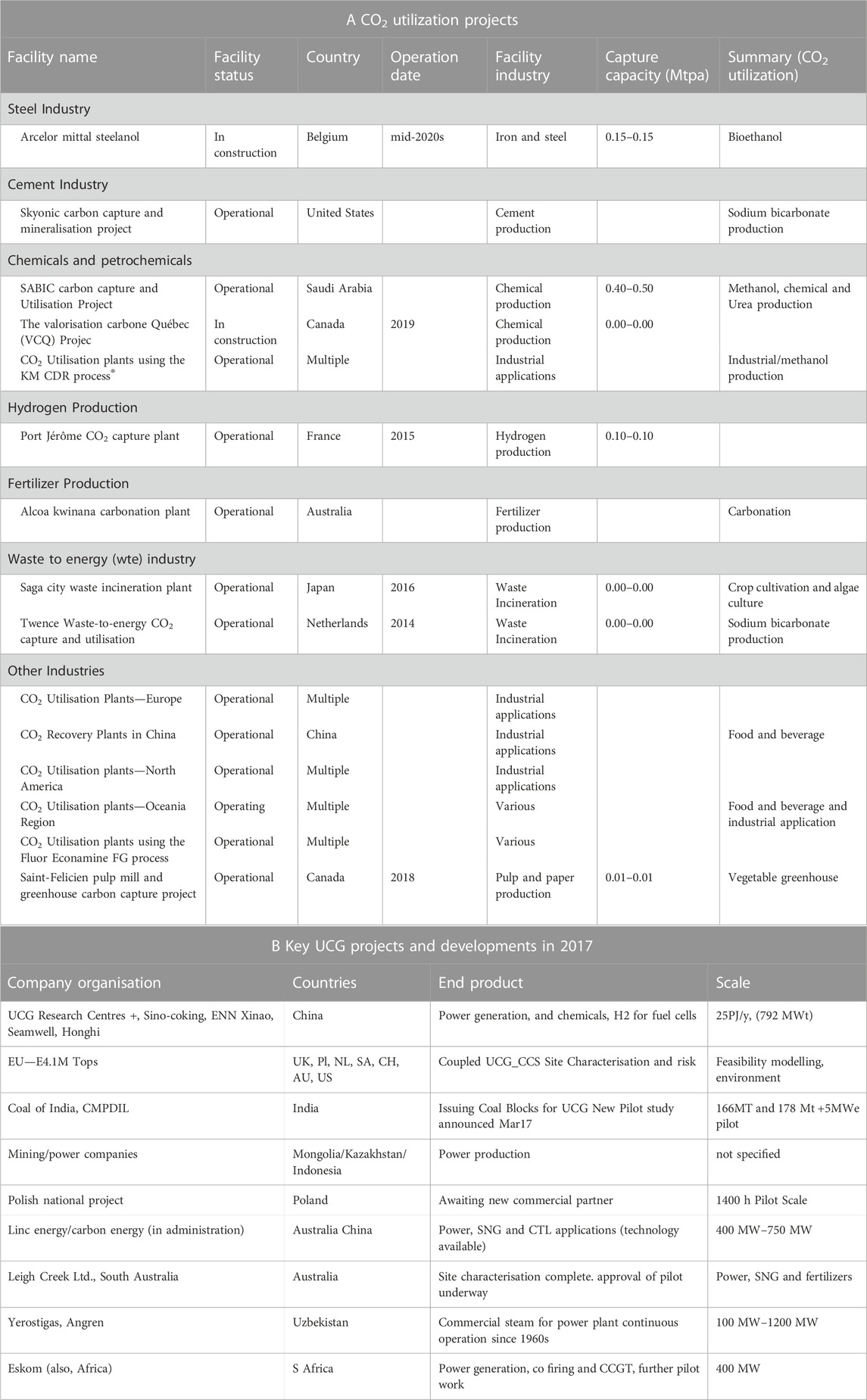
TABLE 7. CO2 Utilization Projects and Key UCG projects and developments in 2017.
Under the guidance of national policy and with the support of government departments at all levels, China has built more than a dozen CCS demonstration facilities with a CO2 capture capacity of over ten thousand tons in coal-fired power plants and coal chemical plants. The largest CO2 capture capacity in these facilities is over 10 million tons per year. In addition, CO2 injection demonstrations have been conducted in the enhanced oil recovery and carbon storage industry, with the largest reserves exceeding 15 million tons per year. Completed demonstration projects include 10 million tons per year for brackish terrestrial CO2 storage projects, microalgae carbon capture projects (Global CCS Institute, 2017). See Table 6 for an overview of major CCUS pilot demonstration projects in China. Table 8 shows key project events and the budget for the Shenhua CCS project.
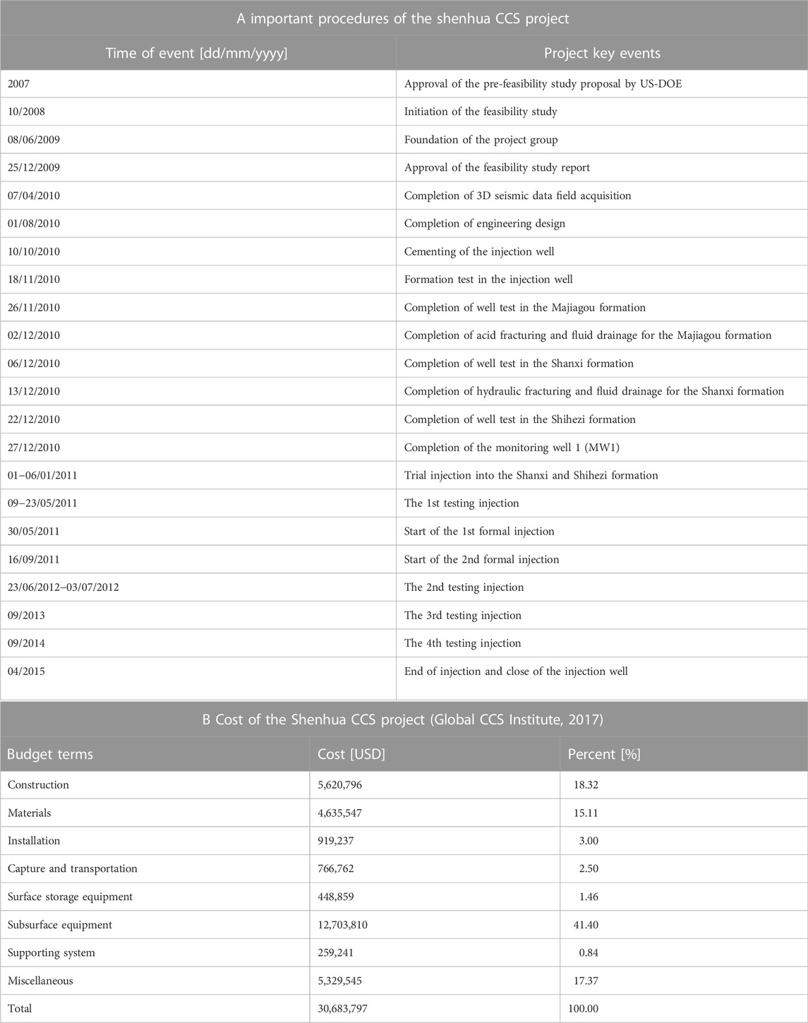
TABLE 8. Important procedures and cost of the Shenhua CCS project.
When UCG is fused with a CCS system, there is a reduction in the cost associated with CO2 capture and compression. Therefore, one of the policies for sustaining worldwide energy demand is the effective application of UCG technology. Research by Ni and Jiang (2016) Shows the base case cost evaluation and relates the power generation cost of theoretical plants of NGCC, IGCC, UCGCC and PC lacking the installation of CCS systems. It was established that IGCC generated the maximum cost with a range from $104–117/MWh. When the coal price dropped to $10/ton, the generation costs of PC and UCGCC were similar, at about $45/MWh.
Conversely, PC showed further coal price sensitivity and its price was more than the UCGCC when the coal price was higher than $10/ton. NGCC would show massive competitiveness with a price lower than UCGCC if the natural gas price was less than $4.50/GJ, or $4.85/kscf. Overall, the UCGCC generation cost was low ($45–50/MWh) and showed less sensitivity towards the fuel price. The reason is that UCG joins both coal mining and utilization processes and evaluates only the royalties and severance fees. Thus, this saves substantial prices in obtaining coal, its storage, and handling.
Ni and Jiang (2016) further conducted an experiment to relate the generation cost ($/MWh) and the cost of captured CO2 by installing a Selexol pre-combustion capture system on IGCC and UCGCC plants. In addition, an amine post-combustion capture system was installed on the NGCC and PC plants. It was observed that IGCC-CCS had the peak cost. The cost gap between the IGCC and UCGCC was more significant in the CCS case than in the base case. This means there is a significant impact on the PC relative to the UCGCC when setting up the CCS system. Low fuel prices were recorded for the NGCC-CCS (below $4.50/GJ). Conversely, the UCGCC-CCS recorded decreased generation cost than the NGCC-CCS at increased fuel prices (above $4.50/GJ). It is evidenced that the highest CO2 capture cost was recorded for the NGCC-CCS, followed by the IGCC-CCS and PC-CCS. UCGCC-CCS recorded the least cost for CO2 capture. Decreased CO2 capture cost obtained by the UCGCC process makes it a massive benefit in the CO2 consumption market.
UCG-based power plants are similar to IGCC power plants, except for surface gasifiers (Burton et al., 2006). A simplified comparison of the capital costs of UCG power plants and IGCC can be made by comparing the required process units and capacity. The published cost estimate of the IGCC process unit is based on the analysis of a GE airflow gasifier with a carbon capture function (Burton et al., 2006). According to the design configuration and simulation results, the main differences between UCG and IGCC ground equipment. By eliminating the surface gasification device and reducing the size of the ASU, the overall capital cost of the UCG power plant is expected to be saved by 33%.
Several studies have been published on the economics of IGCC power plants and pulverized coal power plants, the current standard. According to the information developed by Burton et al. (2006), the cost of a supercritical pulverized coal (SCPC) power plant ranges from $1200 to $1460/kW. The same study estimates that the next-generation of IGCC power plants will be about 10% more expensive than the SCPC plants (vs. the current 20–25% premium). These places the cost of IGCC plants at $1440 to $1750/kW current technology, and $1320 to $1600/kW (advanced technology). Peng et al. (2016) has estimated the cost of an IGCC plant at $1,350/kW, which is in the same range as that estimated by Burton et al. (2006) for the advanced technology IGCC plants.
Much research has been published on the economics of IGCC power plants and the current standard pulverized coal power plants (Burton et al., 2006) states that the charge range of supercritical pulverized coal (SCPC) power plants are between $1200 to $1460/kW. Furthermore, future IGCC power plants will be approximately 10% cost higher than the SCPC power plants. These bring the cost of the IGCC plant to current technology from $1440 to $1750/kW and $1320 to $1600/kW (advanced technology). Peng et al. (2016) and (Burton et al., 2006) estimates a similar cost range of the IGCC plant or the advanced technology IGCC plant to be $1350/kW.
Another indicator of cost competitiveness is electricity prices (COE). Estimates by Peng et al. (2016) place COE for IGCC plants and SCPC at $46.6/MWh and $49.9/MWh. An advanced competitive economic study (Nakaten et al., 2014) indicates that for UCG power generation, the Levelized COE is estimated at €49/MWh without CCS and €72/MWh with CCS. Regarding figures released by Ergo Exergy (Maev et al., 2018), UCG-IGCC plants significantly have lower COE and construction costs. The cost of capital for a 177 MW plant presented by Maev et al. (2018) is approximately $600/KW and $450/KW for a 280 MW plant. The COE is projected to be around $12/MWh. According to Green (2018), CO2 emissions from UCG power generation using combined cycle gas turbine (CCGT) range from 570 to 785 kg CO2/MWh without resources to CCS, compared to 400 kg CO2/MWh natural gas. CCS can decrease UCG emissions to less than 100 kg CO2/MWh. These remarkable figures make UCG comparable to renewable energy and achieve the highest fossil fuel emissions in CCS.
Recently, UCG projects are common in China, South Africa, and Australia. These projects have chemical plants or operating power plants powered by UCG syngas. However, in Canada and the US, these projects are still in their development stages (Clean Air Task Force Report, 2009). Studies by Burton et al. (2006) state that the recent promising blend of technological features offers a commercially viable opportunity for the UCG process by enhancing the UCG technical variables and lowering the extreme effect on the environment. The same studies indicate that the first nation to introduce a general program for UCG R&D was USSR. By 1928, different national research projects had been organized, and in 1933 underground experiments began in Kurtova, Tula, Shati, Rennis-Kuznets, Korevka, and Lysychansk. While carrying out the experimental plan, theoretical plan and laboratory research were also carried out.
Currently, in the US, there are no UCG facilities in operation, and no major company is working on UCG research, but many other research projects are underway. In other regions, UCG projects have set off a new upsurge (Dalton, 2004) demonstrates the primary UCG projects overseas in the 20th century (from 1934 to 1997). Primary UCG projects from 2007 to 2011. In 2017, Geeta and Prabu (2017) pointed out that UCG activities were intense in many countries, which signifies a reduction in global UCG development 3 years ago. Table 7 shows the major UCG schemes and progresses in 2017.
The Chinese government has decided to develop the UCG project to reduce the pollution of coal-fired power plants, Private companies, like Seamwell Int. Hongli Clean Energy and others continue to maintain an interest in UCG feasibility and semi-commercial studies, mainly in Inner Mongolia, for the production of chemicals and power from UCG syngas (Khadse et al., 2007). According to Daggupati et al. (2010), this places UCG test centers in China to approximately 15 (Blinderman, 2005).
This paper has provided an overview of UCG coupled with the CCS/CCUS technology process. These technologies emerge as excellent green technology which will keep global warming in check along with securing energy demands. From the above study, the following conclusions can be drawn;
• Although the knowledge of UCG is not current and can be traced back about 100 years ago, most global coal-producing regions have recently renewed interest in UCG technology. UCG is an integrative process because it involves different engineering phases (chemical, drilling, geotechnical) and connected disciplines (hydrogeology, hydrology).
• The processes by which UCG promotes carbon capture are identical to surface-based IGCC. However, UCG has no ash treatment plants, coal mining, or surface gasification. Therefore, under equal settings, the general thermal efficiency of the UCG power plant is higher than the equivalent surface IGCC, and the CO2 intensity is lower, especially considering the general CO2 emissions, including CO2 emissions from coal mining.
• Countries most interested and active in R&D UCG projects are the US, China, South Africa, United Kingdom, India, Poland, Canada, Australia, and Hungary.
• The Countries closest to UCG commercialization are China, South Africa, and North America. Presently, South Africa is ahead of the commercialization of UCG, investing more than $100 million in three major electricity projects.
• Many developments in the aforesaid countries rely on CRIP UCG technology developed in the United States in 1975 by the Lawrence Livermore National Laboratory. However, most UCG projects, both in operation and presently under expansion over the last 20 years, use UCG technology from Canadas Ergo Exergy Technologies. In addition, several Ergo Energy’s UCG projects are under consideration in Canada, India, Turkey, Argentina, and Pakistan.
• High UCG practicability to be carried out in a CO2 mode is a promptly accessible enhancer for gasification. For proficient gasification, preheating the CO2 as a gasifying medium to high temperatures is cost-effective relative to the generation of superheated steam in a UCG steam-based operation.
• Chemical absorption-based PCC technology is a short-term practical option for deploying marketable CCS. This technology has been widely validated through pilot plant testing, and various aspects of the technology have been investigated through modeling and simulation. Marketable products for modeling and simulating such developments are now available along with the technology and can be store-bought from various vendors such as Alstom, Shell, and Siemens.
ST: data curation and writing—original draft preparation. YZ: supervision. MS: conceptualization, methodology, software, and investigation. FZ: formal analysis and revision. YL: english language modification. PT: writing—reviewing and editing.
The authors acknowledge the financial supports of the National Natural Science Foundation of China (51974033, 52274060, 52206218), the National Overseas Study Foundation of China (201708420106), the Yangtze Youth Talents Fund (No. 2015cqt01) and the Natural Science and Engineering Research Council of Canada.
The authors declare that the research was conducted in the absence of any commercial or financial relationships that could be construed as a potential conflict of interest.
All claims expressed in this article are solely those of the authors and do not necessarily represent those of their affiliated organizations, or those of the publisher, the editors and the reviewers. Any product that may be evaluated in this article, or claim that may be made by its manufacturer, is not guaranteed or endorsed by the publisher.
APEC (2019). APEC energy working Group 2019 exchange and training on clean coal technology and clean energy policy. Beijing, China: SOM Steering Committee on Economic and Technical Cooperation (SCE), Energy Working Group (EWG).
Barnwal, R. P., Bharti, S., Misra, S., and Obaidat, M. S. (2017). UCGNet: Wireless sensor network-based active aquifer contamination monitoring and control system for underground coal gasification. Int. J. Commun. Syst. 30, e2852. doi:10.1002/dac.2852
Bhutto, A. W., Bazmi, A. A., and Zahedi, G. (2013). Underground coal gasification: From fundamentals to applications. Prog. Energy Combust. Sci. 39, 189–214. doi:10.1016/j.pecs.2012.09.004
Blinderman, M. S., and Anderson, B. (2003). “Underground coal gasification for power generation: Efficiency and CO2-emissions,” in Proc. 12th International Conference on Coal Science, 2–6 November 2003 (Cairns, Australia: IEEE), 13.
Blinderman, M. S., and Jones, R. M. (2002). “The Chinchilla IGCC project to date: Underground coal gasification and environment,” in Proceedings of 2002 Gasification Technologies Conference, 21-July 2002 (San Francisco, USA: IEEE), 1–10.
Blinderman, M. S. (2005). UCG history. Available at: http://www.ergoexergy.com/eUCG_his.htm.
Burton, E., Friedmann, J., and Upadhye, R. (2006). Best practices in underground coal gasification; draft report on work performed by the University of California. Cambridge: Lawrence Livermore National Laboratory for the United States Department of Energy, 119.
Cena, R. J., Britten, J. A., and Thorness, C. B. (1988). “Resource recovery and cavity growth during the Rocky Mountain I field test,” in 14th UCG Annual Symposium, 10 January 1988 (Chicago, USA: IEEE), 5.
Chen, F., Pan, X., Liu, H. T., and Yao, K. (2013). O2/CO2 underground coal gasification model test. J. China Coal Soc. 88, 495e500. doi:10.13225/j.cnki.jccs.2013.s2.022
Clean Air Task Force Report (2009). Coal without Carbon: An investment plan for federal action. Boston, MA: Clean Air Task Force, 5.
CO2 Earth (2017). CO2 earth projections. Available at: https://www.CO2.earth/2100-projections (Accessed Feburary, 2020).
Couch, G. R. (2009). Underground coal gasification. London,UK: IEA Clean Coal Centre. International Energy Agency.
Daggupati, S., Mandapati, R. N., Mahajani, S. M., Ganesh, A., Mathur, D. K., Sharma, R. K., et al. (2010). Laboratory studies on combustion cavity growth in lignite coal blocks in the context of underground coal gasification. Energy 35, 2374–2386. doi:10.1016/j.energy.2010.02.015
Daggupati, S., Mandapati, R. N., Mahajani, S. M., Ganesh, A., Sapru, R. K., Sharma, R. K., et al. (2011). Laboratory studies on cavity growth and product gas composition in the context of underground coal gasification. Energy 36, 1776–1784. doi:10.1016/j.energy.2010.12.051
Dalton, S. (2004). Cost comparison IGCC and advanced coal. Available at: http://www.climatevision.gov/pdfs/coal_roundtable/dalton.pdf#search=%22Stu%20Dalton%20IGCC%22.
DECC Report (2015). Underground coal gasification – evidence statement of global warming potential. London: Atkins Report to DECC.
DOE/NETL (2006). in The gas turbine handbook. Editor R. Dennis (Morgantown, WV: National Energy Technology Laboratory).
Department of Energy EIA Energy Information Administration (2009). Share of world coal consumption by region, Reference Case 1990-2030.
Dixon, T. (2016). Update on CCUS in the global climate picture and IEAGHG activities Carbon capture utilization and storage conference. Available at: http://www.ieaghg.org/docs/General_Docs/IEAGHG_Presentations/CCUS_DC_Dixon_v3.pdf (Accessed Feburary, 2017).
DOE/NETL (2015b). IGCC project examples. Available at: http://www.netl.doe.gov/research/coal/energy-systems/gasification/gasifipedia/project-examples.
DOE/NETL (2015a). Nitrogen oxides (NOx) emissions from coal. Available at: http://www.netl.doe.gov/research/Coal/energy-systems/gasification/gasifipedia/nitrogen-oxides.
EIA (2003). Annual energy outlook 2003. Washington, D.C.: U.S. Department of Energy, Energy Information Administration.
EIA, International (2003). Energy annual 2001. Washington, D.C.: U.S. Department of Energy, Energy Information Administration, 114–115.
EIA, International (2002). Energy outlook 2002. Washington, D.C.: U.S. Department of Energy, Energy Information Administration.
Eskom Holdings Ltd 2008. Revised environmental scoping report for the proposed combined cycle gas turbine (CCGT) power plant in the amersfoot area, mpumalanga province, Final Report, DEAT REF 12/12/20/1074.
EU (2020). Long-term low greenhouse gas emission development strategy of the European Union and its members. Zagreb: European Union.
European Technology (2005). European technology Platform for zero emission fossil fuel power plants (ZEP), CO2 capture and storage (CCS), a key solution for combating climate change. Brussels, Germany: The European Technology Platform for Zero Emission Fossil Fuel Power Plants (ZEP).
Friedmann, S. J. (2006). “Carbon sequestration,” in Proc. 2006 Energy Symposium, 16-20 June 2003 (Madison, WI, USA: IEEE), 1–10.
Geeta, K., and Prabu, V. (2017). CO2 -air based two stage gasification of low ash and high ash Indian coals in the 2 context of underground coal gasification. Energy. 11, 27. doi:10.1016/j.energy.2017.11.027
Gem (2021). Global Energy Monitor underground coal gasification. Available at: www.gem.wiki/underground_coal_gasification.
Green, M. (2018). Recent developments and current position of underground coal gasification. Proc. Inst. Mech. Eng. Part A J. Power Energy 232, 39–46. doi:10.1177/0957650917718772
Gregg, D. W., Hill, R. W., and Olness, D. U. (1976). An overview of the Soviet effort in underground coal gasification. Berkeley, CA, USA: Lawrence Livermore National Laboratory, University of California.
Guan, L. I., Wen, L. I., and Jia, W. E. I. (2016). Monitoring and control system of UCG process based on S7—300 PLC. J. North China Inst. Sci. Technol. 13, 86–91. doi:10.4028/www.scientific.net/AMM.496-500.1376
Higman, C., and van der Burgt, M. (2008). Gasification. 2nd edn. Oxford, UK: Gulf Professional Publishing.
Hill, R. W., and Shannon, M. J. (1981). “The controlled retracting injection point (CRIP) system: A modifi ed stream method for in-situ coal gasifi cation,” in 7th Underground Coal Conversion Symposium, 8 September 1981 (CA, USA: Fallen Leaf Lake), 10.,
Hill, R. W. (1983). The Centralia partial-seam CRIP test. Livermore, CA: Lawrence LivermoreNational Laboratory.
IEA (2015). Energy and climate change – world energy outlook special report. Paris: The annual World Energy Outlook.
Jinyi, W., and Shisen, X. (2014). CO2 capture RD&D proceedings in China Huaneng Group. Int. J. Coal Sci. Technol. 1 (1), 129–134. doi:10.1007/s40789-014-0013-6
Khadse, A., Qayyumi, M., Mahajam, S., and Aghalayam, P. (2007). Underground coal gasification: A new clean coal utilization technique for India. Energy 32, 2061–2071. doi:10.1016/j.energy.2007.04.012
Khan, M. M., Mmbaga, J. P., Shirazi, A. S., Trivedi, J., Liu, Q., and Gupta, R. (2015). Modelling underground coal gasification—a review. Energies 8, 12603–12668. doi:10.3390/en81112331
Klimenko, A. Y. (2009). Early ideas in underground coal gasification and their evolution. Energies 2, 456–476. doi:10.3390/en20200456
Kostúr, K., Laciak, M., Durdán, M., Kacur, J., and Flegner, P. (2015). Low-calorific gasification of underground coal with a higher humidity. Measurement 63, 69–80. doi:10.1016/j.measurement.2014.12.016
Kotyrba, A., and Stanczyk, K. (2017). Sensing underground coal gasification by ground penetrating radar. Acta Geophys. 65, 1185–1196. doi:10.1007/s11600-017-0095-9
Kumar, H. (2014). Underground coal gasification: An alternate economical and viable solution for future sustainability. Int. J. Eng. Sci. Invent. 3(1), 56–68.
Lavis, S., Courtney, R., and Mostade, M. (2013). Underground coal gasification. United Kingdom: Woodhead Publishing Limited. doi:10.1533/9780857097309.2.226
Liang, J., Liu, S., and Yu, L. (1999). “Trial study on underground coal gasification of abandoned coal resource,” in Proceedings of the '99 international symposium on mining science and technology. Editors H. Xie, and T. S. Golosinki (Beijing: Mining Science and Technology), 271–275.
Linc Energy (2015). Linc energy - yerostigaz. Available at: http://www.lincenergy.com/acquisitions_yerostigaz.php.
Maev, S., Blinderman, M. S., and Gruber, G. P. (2018). Underground coal gasification (UCG) to products: Designs, efficiencies, and economics. doi:10.1016/B978-0-08-100313-8.00013-X
Mandapati, R. N., Daggupati, S., Mahajani, S. M., Aghalayam, P., Sapru, R. K., Sharma, R. K., et al. (2012). Experiments and kinetic modeling for CO2 gasification of indian coal chars in the context of underground coal gasification. Ind. Eng. Chem. Res. 51, 15041–15052. doi:10.1021/ie3022434
Marques, G., Ferreira, C. R., and Pitarma, R. (2018). A system based on the internet of things for real-time particle monitoring in buildings. Int. J. Environ. Res. Public Health 15, 821. doi:10.3390/ijerph15040821
Mellors, R., Yang, X., White, J. A., Ramirez, A., Wagoner, J., and Camp, D. W. (2016). Advanced geophysical underground coal gasification monitoring. Mitig. Adapt. Strateg. Glob. Chang. 21, 487–500. doi:10.1007/s11027-014-9584-1
Miller, B. G. (2005). Coal energy systems. Cambridge: Elsevier Academic Press Inc. All rights reserved.
Mojibul, S., and Mohammad, G. R. (2015). Prospect of underground coal gasification in Bangladesh. Procedia Eng. 105, 537–548. doi:10.1016/j.proeng.2015.05.087
Mostade, M. (2014). Underground coal gasification (UCG) – The path to commercialization. Available at: https://www.researchgate.net/publication/.
Nakaten, N., Schlüter, R., Azzam, R., and Kempka, T. (2014). Development of a techno-economic model for dynamic calculation of cost of electricity, energy demand and CO2 emissions of an integrated UCG-CCS process. Energy 66 (1), 779–790. doi:10.1016/j.energy.2014.01.014
Ni, L., and Jiang, D. (2016). A study on the path to global commercialization of CCS technology. Beijing: China Coal Industry Publishing House.
Nourozieh, H., Kariznovi, M., Chen, Z., and Abedi, J. (2010). Simulation study of underground coal gasification in Alberta reservoirs: Geological structure and process modeling. Energy fuels. 24, 3540–3550. doi:10.1021/ef9013828
Nurzynska, K., Iwaszenko, S., and Choroba, T. (2014). “Database application in visualization of process data,” in Beyond Databases, Architectures and Structures—Proceedings of the 10th International Conference BDAS 2014, 16 June 2014 (Cham, Switzerland: Springer), 537–546.
Peng, P., Kirtipal, B., and Junior, N. (2016). Competitiveness and cost sensitivity study of underground coal gasification combined cycle using lignite. Washington, DC: American Chemical Society. doi:10.1021/acs.energyfuels.6b00019
Perkins, G., and Sahajwalla, V. (2006). A numerical study of the effects of operating conditions and coal properties on cavity growth in underground coal gasification. Energy fuels. 20, 596–608. doi:10.1021/ef050242q
Power (2011). Underground coal gasification: Another clean coal option. Houston, Texas: Power magazine.
Prabu, V., and Jayanti, S. (2012). Laboratory scale studies on simulated underground coal gasification of high ash coals for carbon neutral power generation. Energy 46, 351–358. doi:10.1016/j.energy.2012.08.016
Roddy, D. J., and Younger, P. L. (2010). Underground coal gasification with CCS: A pathway to decarbonising industry. Energy Environ. Sci. 3, 400–407. doi:10.1039/b921197g
Saravanan, K., Anusuya, E., Kumar, R., and Le, H. S. (2018). Real—Time water quality monitoring using internet of things in SCADA. Environ. Monit. Assess. 190, 556. doi:10.1007/s10661-018-6914-x
Sasol, E. (2013). Sasol and Eskom sign research agreement for UCG collaboration in South Africa. Johannesburg, South Africa: Sasol Media release, Issued by Alex Anderson. Available at: https://www.sasol.com/media-centre/media-releases/sasol-and-eskom-sign-research-agreement-ucg-collaboration-south-africa.
Shafirovich, E., and Varma, A. (2009). Underground coal gasification: A brief review of current status. Ind. Eng. Chem. Res. 48, 7865–7875. doi:10.1021/ie801569r
SHS (2012). Swan hill Synfuels.Swan Hills in-situ coal gasification technology development final outcomes report. Central Alberta, BC: Swan Hills Synfuels.
Stanczyk, K., Kapusta, K., Wiatowski, M., Swiadrowski, J., Smolinski, A., Rogut, J., et al. (2012). Experimental simulation of hard coal underground gasification for hydrogen production. Fuel 91, 40–50. doi:10.1016/j.fuel.2011.08.024
Synfuels, S. H. (2012). Submission to AUC and AESRD application for power plant. Alberta, Canada: Swan Hills.
The Trades Union Congress (2014). The economic benefits of CCS in the UK. CCSA and TUC report. Available at: https://www.tuc.org.uk/sites/default/files/carboncapturebenefits.pdf.
The World bank (2014). Understanding CO2 emissions from the global energy sector. Washington, DC: Live Wire, 2014/5. World Bank. Available at: https://openknowledge.worldbank.org/handle/10986/17143.
Thorsness, C. B., and Britten, J. A. (1989). Lawrence Livermore national laboratory underground coal gasification project: Final report. Berkeley, CA, USA: Lawrence Livermore National Laboratory, University of California.
Tollefson, J. (2011). Low-cost carbon-capture project sparks interest. Nature 469 (7330), 276–277. doi:10.1038/469276a
UGE (1999). Underground Coal Gasifi cation – first trial in the framework of a community collaboration. Final Summary Report.
Uppal, A. A., Alsmadi, Y. M., Utkin, V. I., Bhatti, A. I., and Khan, S. A. (2018). Sliding mode control of underground coal gasification energy conversion process. IEEE Trans. Control Syst. Technol. 26, 587–598. doi:10.1109/tcst.2017.2692718
Uppal, A. A., Bhatti, A. I., Aamir, E., Samar, R., and Khan, S. A. (2014). Control oriented modeling and optimization of one-dimensional packed bed model of underground coal gasification. J. Process Control 24, 269–277. doi:10.1016/j.jprocont.2013.12.001
U.S. Department of Energy (2006). Underground coal gasification workshop. Kolkata, India: U.S. Department of Energy.
Wang, J. H., Wang, H. J., and Wang, Z. T. (2017). Design of UCG intelligent monitoring system based on wireless ad hoc network. Coal Mine Mach. 38, 9–11. doi:10.13436/j.mkjx.201712004
Wang, M., Lawal, A., Stephenson, P., Sidders, J., and Ramshaw, C. (2011). Postcombustion CO2 capture with chemical absorption: A state-ofthe-art review. Chem. Eng. Res. Des. 89 (9), 1609–1624. doi:10.1016/j.cherd.2010.11.005
Keywords: underground coal gasification (UCG), UCG modules, UCG CCUS, UCG-ICGCC, cost
Citation: Takyi SA, Zhang Y, Si M, Zeng F, Li Y and Tontiwachwuthikul P (2023) Current status and technology development in implementing low carbon emission energy on underground coal gasification (UCG). Front. Energy Res. 10:1051417. doi: 10.3389/fenrg.2022.1051417
Received: 22 September 2022; Accepted: 21 November 2022;
Published: 06 January 2023.
Edited by:
Hui Zhou, Tsinghua University, ChinaReviewed by:
Yang Xiao, Xi’an University of Science and Technology, ChinaCopyright © 2023 Takyi, Zhang, Si, Zeng, Li and Tontiwachwuthikul. This is an open-access article distributed under the terms of the Creative Commons Attribution License (CC BY). The use, distribution or reproduction in other forums is permitted, provided the original author(s) and the copyright owner(s) are credited and that the original publication in this journal is cited, in accordance with accepted academic practice. No use, distribution or reproduction is permitted which does not comply with these terms.
*Correspondence: Yindi Zhang, emhhbmd5aW5kaWh1c3RAZm94bWFpbC5jb20=
Disclaimer: All claims expressed in this article are solely those of the authors and do not necessarily represent those of their affiliated organizations, or those of the publisher, the editors and the reviewers. Any product that may be evaluated in this article or claim that may be made by its manufacturer is not guaranteed or endorsed by the publisher.
Research integrity at Frontiers
Learn more about the work of our research integrity team to safeguard the quality of each article we publish.