 Xuzhong Zheng1
 Dan Wu1Bo Zhou2Zhuangyin Wang3Li Liu1Junchao Yu1
 Qing Yuan1*Song Jiang1*Jiamin Zhao1Yue Wang1
- 1Shandong Provincial Key Laboratory of Chemical Energy Storage and Novel Cell Technology, School of Chemistry and Chemical Engineering, Liaocheng University, Liaocheng, China
- 2Jinan Noah Emergency Equipment Co., Ltd., Jinan, China
- 3Liaocheng Luxi Chemical Engineering Design Co.,Ltd., Liaocheng, China
Thermal stimulation methods of hydrate exploitation with chemical self-heating solution began to be investigated in the recent years. However, the exothermic characteristics of chemical self-heating solution during the gas hydrate exploitation process was not investigated systematically now. In this work, the effects of reagent concentration, acid variety, acid concentration on the exothermic characteristics were investigated by a self-designed high pressure autoclave with a 11.75 L volume, whose diameter and length is 100 and 1,500 mm, respectively. The experimental results showed that the temperature of hydrate reservoir will change in a wide range (from 100°C to −3°C) during the injection process of self-heating solution which was a large challenge to control the rate of heat release. During the self-heating solution injection, the temperature decreased quickly because of the strong endothermic reaction of hydrate dissociation promoted by the salt effect of self-heating solution, and then the temperature increased quickly because of exothermic reaction of self-heating solution. The exothermic rate of self-heating solution increased with the increase of reagent concentration, the acid concentration and the acidity. In all of the experiments, the temperatures near the inlet entrance were much higher than that in the deeper area, which illustrated that the effective heating area is the areas near the entrance. In the end, the different injection mode of mixed injection and sectional injection was also investigated, and it was found that the temperature peak in the near area with mixed injection mode is higher than that with sectional injection mode, however, the exothermic performance with sectional injection mode is better than that with mixed injection in the area far away from the inlet entrance. The exothermic characteristics studies of self-heating solution in this work can lay the necessary foundation of the further studies of self-heating solution in the exploitation of natural gas hydrate.
1 Introduction
Natural gas hydrates (NGHs) are ice-like crystals that is widely distributed in the marine and permafrost with appropriate pressure and temperature (Liu et al., 2020), which is composed of natural gas (methane, ethane et al.) and water. The gas hydrate has been used in many aspects, for example, salt removal (Chen et al., 2020; Hu et al., 2021; Wu et al., 2021), gas separation (Liu et al., 2013; Liu et al., 2019a; Mu et al., 2022), gas storage (Sun et al., 2019; Zeng et al., 2020; Sun et al., 2021). However, the most important usage of hydrate is used as energy sources. The amount of natural gases trapped in hydrate-bearing sand layers are 1013 m3 STP—1015 m3 STP (Zhao et al., 2015a; Chen et al., 2015), which illustrated that the hydrate is a promising kind of energy resource due to its tremendous reserves, cleanness and high energy density (Fan et al., 2017; Yang et al., 2019a) and have gained worldwide attention as a potential alternative energy resource (Liu et al., 2019b). In recent years, several hydrate exploration tests have been conducted in the worldwide, such as Shenhu area (South China Sea) (Kou et al., 2022), Bay of Bengal (India), and Mount Elbert (Alaska) (Yang et al., 2012; Li et al., 2021). Due to its potential as a kind of clean energy resources, the studies of natural gas hydrate exploitation methods have attracted widely attentions. The exploitation methods include depressurization (Liu et al., 2019b; Kou et al., 2022), thermal stimulation (Yuan et al., 2013a; Nair et al., 2016; Ma et al., 2021), inhibitor injection (Yuan et al., 2011; Yuan et al., 2013a; Zheng et al., 2015; Zeng et al., 2022), gas replacement methods (Yuan et al., 2012; Yuan et al., 2013b; Xie et al., 2021), and the combination of above methods (Nair et al., 2018; Yang et al., 2019b). The depressurization method is thought to be a good choice for gas hydrate dissociation with the merits of simplification, feasibility and economic efficiency. However, the low rate of hydrate decomposition due to the so-called “self-protecting” effect would hinder the economic yield of natural gas from hydrate reservoir seriously (Liu et al., 2019b). In order to increase the exploitation rate of depressurization method, the combination method of depressurization and thermal simulation is thought to be a feasible method (Moridis et al., 2011; Li et al., 2012; Feng et al., 2015a), because the thermal simulation can offer the needed energy when the decomposition rate of depressurization method decreased. The thermal methods studied in the worldwide can be divided into two kinds: thermal convection mode and thermal conduction mode. The methods with thermal convection mode included the hot water injection method, the hot brine solution injection method (Zhang et al., 2008; Cranganu, 2009; Yuan et al., 2013a; Feng et al., 2015a; Feng et al., 2015b; Jin et al., 2016; Li et al., 2016; Hao et al., 2017; Wang et al., 2017; Wang et al., 2018; Yu et al., 2019). The methods with thermal conduction mode included the electrical heating method, microwave heating method, solar energy heating method, and wellbore heating (Song et al., 2009; Su et al., 2012; Zhao et al., 2015b; Zhao et al., 2016; Li et al., 2018; Song et al., 2018; Zheng et al., 2018). However, the above mentioned conventional thermal methods cannot send the energy to the deeper area effectively, and most of the injected energy was exhausted by the near area of the hydrate reservoir (Zhang et al., 2008; Cranganu, 2009; Yuan et al., 2013a; Feng et al., 2015b; Wang et al., 2018).
The merits of hot water injection method, hot brine solution injection method are simple and low equipment requirements. However, the most energy was wasted by the heating process of the sediment near the wellbore, which resulted in the energy arrived the deeper sediment is very limited. The limit energy in the deeper area is not beneficial for the exploitation of natural gas hydrate in the later period. Wang et al. (Wang et al., 2018) found that the method of pure hot water injection cannot dissociate the hydrate completely in the reactor due to the limit heating area. Zhang et al. (2008) found that a majority of thermal analysis was consumed by the increasing temperature of non-NGH (natural gas hydrate). The experiments results showed that, in the early period, the hydrate can dissociate quickly because of the hot water energy can arrived the hydrate reservoir effectively; in the later period, the hydrate dissociated much slowly because that the huge energy lost during the hot water flowing process, which means that the effective heating area of hot water is the near wellbore area (Yuan et al., 2013a; Feng et al., 2015b). In addition, those energy losses from the source to the reservoir or through pipelines would also significantly increase the production cost (Cranganu, 2009).
The methods of electrical heating, microwave heating, solar energy heating and wellbore heating can solve the energy loss during the flowing process from the source to the reservoir or through pipelines, but these new thermal methods also have some defects. Li et al. (2018) found that once the electrical heat is injected from the central well, a temperature gradient is observed around the well, and it enlarges continuously towards the boundaries due to heat diffusion. Su et al. (2012) simulate the production potential of hydrate deposit through thermal stimulation by employing the TOUGH + HYDRATE simulator and found that the radioactive radius of the high-temperature heat source at the well is very small and that the hydrate dissociation rate is slow. Song et al. (2009) studied the method of promoting the hydrate dissociation with solar energy, and they found that the penetration depth of heat is limited because of the effect of the heat conduction mode.
To sum up, the conventional thermal method all have the defects of low energy efficiency, small action range, and cannot seed the energy to the deeper area of the hydrate reservoir, which will result in the low dissociation rate of natural hydrate because of the energy lack. So how to increase the thermal effect range is the key factor to the real application of the combination method. In this work, one new method is proposed to increase the energy supply in the deeper area far away from the entrance by self-heating chemical reaction, which is the first time proposed and studied in the application of hydrate exploitation. The chemical reaction used in this work is shown as Eq. 1.
In this work, the effects of reagents concentration, acid variety, acid concentration, injection mode on the thermal effect range of the self-heating solution were investigated in this work. The exothermic characteristics studies of self-heating solution in this work can lay the necessary foundation of the further studies of self-heating solution in the exploitation of natural gas hydrate.
2 Experimental apparatus and procedures
2.1 Experimental apparatus
The experimental apparatus of hydrate exploitation was designed to investigate the further energy offer characteristics of the chemical self-heating solution. The picture and the flow diagram of the apparatus is shown in Figures 1, 2, respectively.
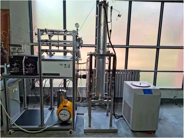
FIGURE 1. The picture of the experimental apparatus.
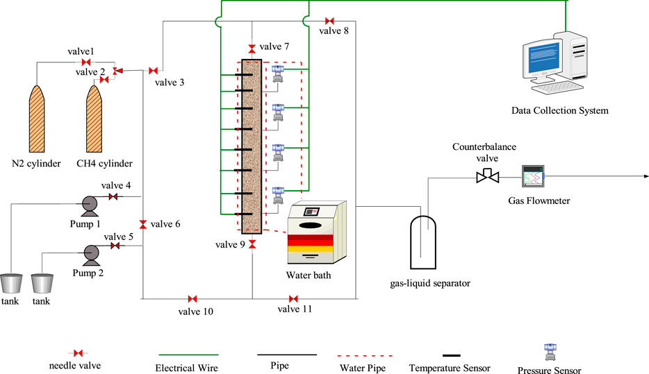
FIGURE 2. The diagram of hydrate exploitation apparatus.
As shown in Figure 2, the apparatus is composed of the gas cylinder, high-pressure pump, high-pressure reactor, data collection system, and temperature control system. The effect of the CH4 cylinder is to supply the needed high pressure of CH4 to assure the hydrate formation successfully, while the N2 cylinder is used to check the tightness of the high-pressure reactor. The solution can be injected into the reactor by the high-pressure pump, whose flow rate range is 10 ml/min∼100 ml/min and the outlet pressure range is 0∼20 MPa. The reactor is designed specially to investigated exothermic characteristic. The length and diameter is 1,500 and 100 mm, respectively. The top and bottom is sealed with flange, while there are two entrances located in the top and bottom flange, respectively. The temperature of the reactor is regulated by water jacket collected with the water bath. The pressure range is 0∼15 MPa, and there are 8 temperature points and 4 pressure points distributed evenly from top to bottom. The temperature sensors are distributed evenly in the reactor, and the exactly positions of eight sensors from the top were 166.7, 333.4, 500.1, 666.8, 833.5, 1,000.2, 1,166.9, and 1,333.6 mm. Each sensor has two temperature measuring points distributed at the center and edge of the reactor, respectively. The temperature precision of temperature sensor is ±0.1 K, while the pressure precision of pressure sensor is ±0.01 MPa. The temperature of the high-pressure reactor is controlled by the water bath, whose precision is ±0.1 K. The temperature and the pressure during the hydrate formation and dissociation process are collected by the data collection system.
2.2 Experimental materials
The names, specifications and manufacture factories of the chemicals used in this work are shown in Table 1. The deionized water was made by ourselves, and the chemicals were used directly in this work without further depuration.
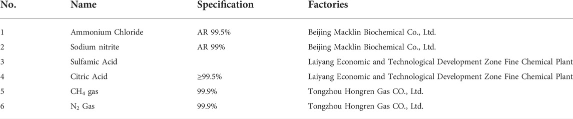
TABLE 1. The details of experimental materials in this work.
2.3 Experimental procedures
The procedures of the experiments can be divided into two parts: CH4 hydrate formation and the exothermic characteristic investigation.
2.3.1 CH4 hydrate formation
In order to simulate the exothermic characteristics of self-heating solution during the exploitation of natural gas hydrate, the first important step is to form representative hydrate sample in each experiment. The mature scheme of hydrate samples preparation method was applied as same as that used in our previous works (Yang et al., 2012; Yuan et al., 2012). The sand of 60–80 mesh was used as the hydrate sediment in this work, while the pure water is used to form hydrate. Before the experiments, the pure water and sands were cooled to 0°C and the reactor was cooled to −3°C for 5 h. The 60–80 mesh sand was mixed water uniformly, and the pure water would become fine ice particles distributed homogeneously among the sands in the reactor. After that, the reactor was sealed, vacuumed for about 20 min, and purged with methane four to five times to ensure the absence of air. Then, methane gas was charged into the reactor from the bottom of the reactor to the desired experimental pressure. Hydrate would nucleate and form among the sediment gradually. Hydrate formation was considered to be finished when the pressure didn’t change for 24 h. The representative hydrate sample was therefore prepared. During the whole process, the temperature and pressure was recorded with the data collection system.
2.3.2 Self-heating solution preparation
The self-heating preparation is composed of two parts: the NaNO2 solution, the NH4Cl solution with acid catalyst. The predetermined concentration of NaNO2 is prepared accurately and put it into a tank. The same concentration of NH4Cl is also prepared accurately in another tank, and the predetermined acid is filled into the NH4Cl solution. And after stirred evenly, the tanks were placed in the water bath to maintain the temperature of two solutions in different water bath. The self-heating solution preparation procedures were finished.
2.3.3 Exothermic characteristic investigation
After the representative hydrate sample was prepared, the following procedures are used to study the exothermic characteristics during the self-heating solution injection process. Firstly, the valve 7, valve 8 and counterbalance valve were opened to release the free gas slowly, and the other valves were all closed. The process was operated very slowly to guarantee the methane hydrate was not dissociated. After the pressure of the reactor reached 7.8 MPa, closed the valve 8, and open the valve 4, valve 5, valve 6, valve 3, valve 9, and valve 11. And then, the solution of NaNO2 and NH4Cl was injected into the hydrate reactor with a certain flow rate by two the high-pressure pumps from the top entrance. During the injection process, the gas and water by the hydrate dissociation were released through the valve 9, valve 11, gas-liquid separator, counterbalance valve and gas flowmeter. When the temperature at position 8A decreased, which illustrated that the self-heating solution had arrived here, the injection process was stopped. The experiments were also operated for 30 min to ensure the injected energy was used to the hydrate dissociated completely. During the whole process, the temperature and pressure were recorded with the data collection system.
3 Results and discussion
3.1 Experimental scheme
In this work, the experimental formation condition and exothermic characteristics research schemes are shown in Tables 2, 3, respectively. It can be seen from Table 2 that the hydrate formation is similar for the seven experiments to ensure the similar hydrate saturation. The porosity of the sediment is about 67%, and the saturation of free water and hydrate are 5%∼6% and 26.44%∼27.56%, respectively. The similar hydrate sample conditions can offer the perfect initial experimental conditions, which is very important to investigate the different impacts on the heat-releasing characteristics. As shown in Table 3, the effects of the reagents concentration, acid variety, acid concentration and injection mode were investigated systemically by the seven experiments.
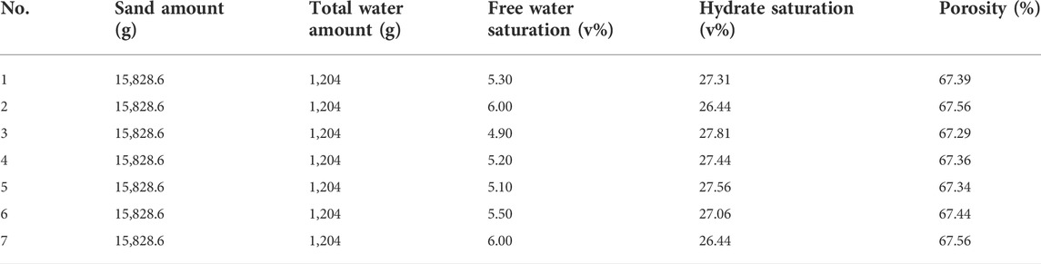
TABLE 2. The hydrate formation conditions of seven experiments.

TABLE 3. The hydrate exploitation schemes of seven experiments.
3.2 Temperature variation characteristics during the self-heating solution injection
The temperature curve during the self-heating solution injection process of seven experiments has similar shapes. We take the experiment 1 as example to demonstrate the temperature changing process. The temperatures curve at different positions in the reactor are shown in Figure 3. It can be seen that the curve shape of position 1A and 2A has similar “well” shape. The temperature decreased firstly because of the intense endothermic process of hydrate dissociation promoted by the salt effect of the self-heating solution, which phenomenon had been reported widely in other studies (Yuan et al., 2013a; Chuvilin et al., 2022). And then, the temperature increased to the highest temperature point 60°C, which is because of the continuous heat supply from the chemical reaction between NaNO2 and NH4Cl. During the temperature increased process, the curve slope of the temperature decreased gradually with time because the heat transfer rate between the reactor and the water bath increased with the increase of the sediment temperature. After that, the temperature decreased slowly because the solution injection is stopped and the energy lost continuously because of heat transfer. The temperature peaks appeared orderly from position 2 to position 8, which reflected the flow process in the hydrate reactor, and the decreased temperature peak from position 2 to position 8 means that the heating capability of self-heating solution decreased orderly. As shown in Figure 3, the temperature at positon 1 to positon 8 all decreased, which means that the self-solution has arrived the bottom of the reactor. However, the temperatures of the point 4–8 only has the decreased process, but has no increased process, which may be due to two reasons. Firstly, the low temperature of the hydrate reservoir inhibits the rate of chemical reaction. Secondly, the reagents were exhausted during the flowing process.
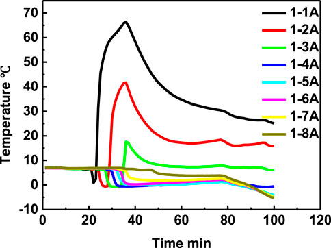
FIGURE 3. Temperatures changing versus time at different positions of experiments 1.
3.3 Effects of reagents concentration on the exothermic characteristic of the chemical self-heating solution
The effect of reagent concentration on the exothermic characteristic of the self-heating solution is studied by experiment 1 and experiment 6 in this work. The temperature changes with time at eight positions of experiment 1 and experiment 6 were shown in Figures 4A,B, respectively. It can be seen that the temperature at position 1A, 2A, 3A with high reagent concentration is higher than that with low reagent concentration. While the temperature at 4A, 5A, 6A, 7A, and 8A did not increase at all.
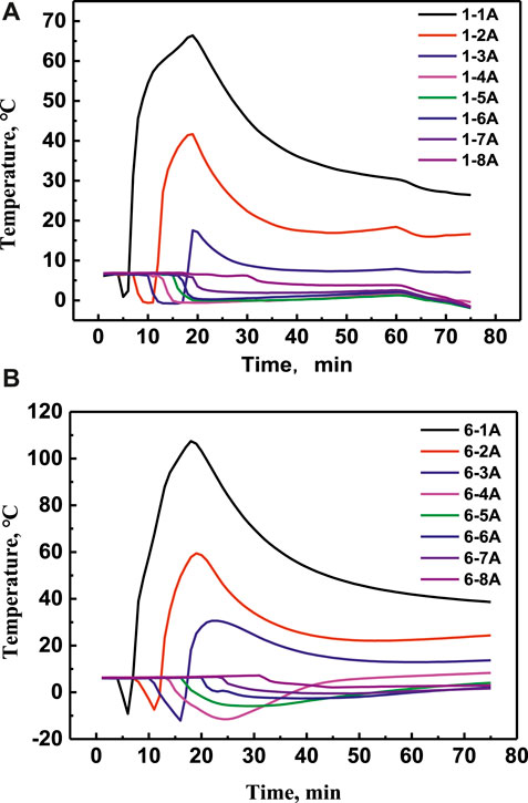
FIGURE 4. Temperatures change at different positions with time at different positions of experiment 1 (A) and experiment 6 (B), respectively.
Figures 5A–D showed that the temperature comparisons at the same position of 1A, 4A, 6A, and 8A, respectively. It can be seen that the lowest temperature at positon 1A in experiment 6 is lower than that in experiment 1, which is because the more reagent concentration in experiment 6 promoted the hydrate dissociated more quickly and absorbed more energy. The temperature at positon 4A with 8 mol/L NaNO2 and NH4Cl is higher than that with 4 mol/L in later period, which means that the heating area with high reagent concentration is larger than that with low reagent concentration. However, the temperature at position 6A and 8A increased very little, which illustrated that the energy cannot seed to deeper area effectively just by increasing the reagent concentration.
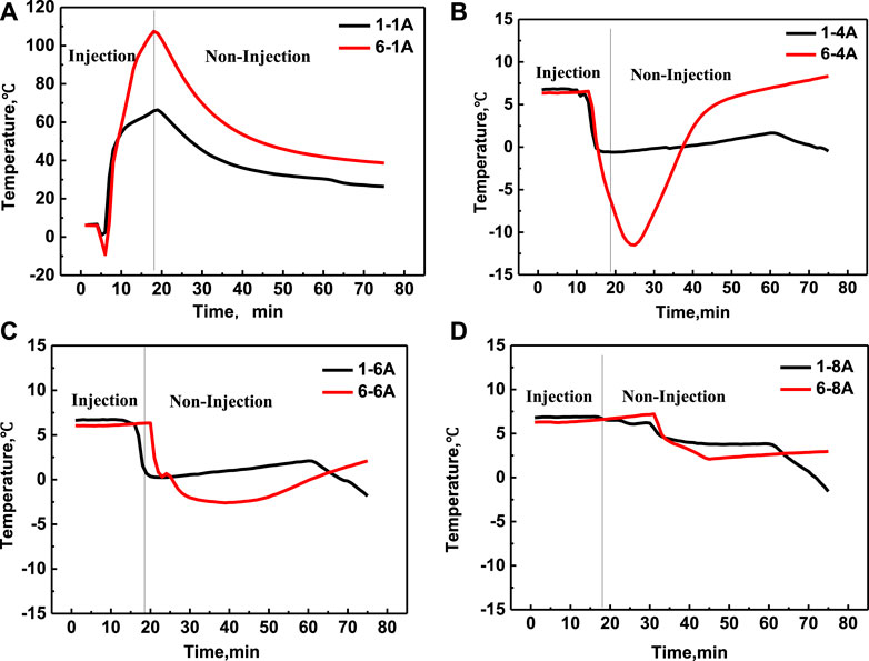
FIGURE 5. Temperature comparison in experiment 1 and experiment 6 at positon 1A (A), positon 4A (B), position 6A (C) and position 8A (D), respectively.
3.4 Effects of injection conditions on the exothermic characteristics of the chemical self-heating solution
In order to decrease the heat loss in the area near the entrance and increase the heat supply of deeper area farther away from the entrance, the sectional injection mode was applied in this work to investigate the effect of injection mode on the heating range and exothermic characteristics. The sectional injection process included two injection procedures: firstly, the solution of NH4Cl was injected individual for a certain time, and then the solution of NaNO2 was injected individual for a certain time. The above two injection steps are repeated until the predetermined amount of solution was injected. The merit of the sectional injection mode is to reduce the hybrid degree of two solutions during the injection process.
The temperature curves versus time of experiment 1 and experiment 3 were shown in Figure 6. It can be seen that the temperature tendency is similar with that of the mixed injection, namely, the temperature decreased firstly because of the energy absorbed by the hydrate dissociation, and then increased slowly due to the dual function of the latent heat and the released chemical heat of the chemical reaction. Also, it can be seen that the temperature of positon 1A with mixed injection can increased to about 70°C, while the temperature of positon 1A with sectional injection only increased to about 25°C (initial temperature of the solution), which means that the sectional injection mode can inhibit the temperature increase in the near area by preventing the mixing process of two solutions. However, the temperature only in the position 1A increased in experiment 3, and the other temperature did not increase at all, which illustrate the sectional injection is not beneficial to increase the energy supply capacity in the deeper area. In addition, the temperature decreased degree in experiments 3 is higher than that in experiment 1, which is because that the NaNO2 and NH4Cl with sectional injection mode was exhausted less than that in experiment 1 due to the less mixing degree of sectional injection mode. So, the salt concentration of the experiment 3 is higher than that of the experiment 1, which will promote the hydrate to decompose faster.
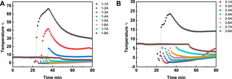
FIGURE 6. Temperature changing comparison versus time at different positions of experiment 1 (A) and experiment 3 (B), respectively.
In order to study the effect of the interval time on the heating range, the experiment 3 and 5 were conducted with interval time of 4 and 2 min, respectively. The temperature curves in eight positons of experiment 3 and experiment 5 are shown in Figures 7A,B, respectively, while the temperature comparison curves at the same depth but different depth were shown in Figures 8A–H, respectively. It can be seen from Figure 8 that, except temperature at positon 1A, the temperatures at other positions of experiment 5 are all higher than that of experiment 3. The experimental results illustrate that the lower interval time is beneficial to increase the heating range area, and the method of adjusting the interval time can be an alternative method to optimize the heating range area.
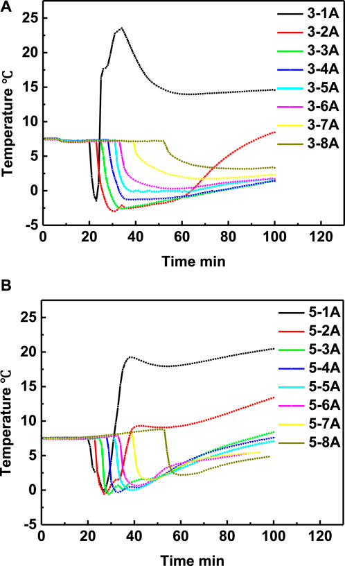
FIGURE 7. Temperature changing comparison versus time at different positions of experiment 3 (A) and experiment 5 (B), respectively.
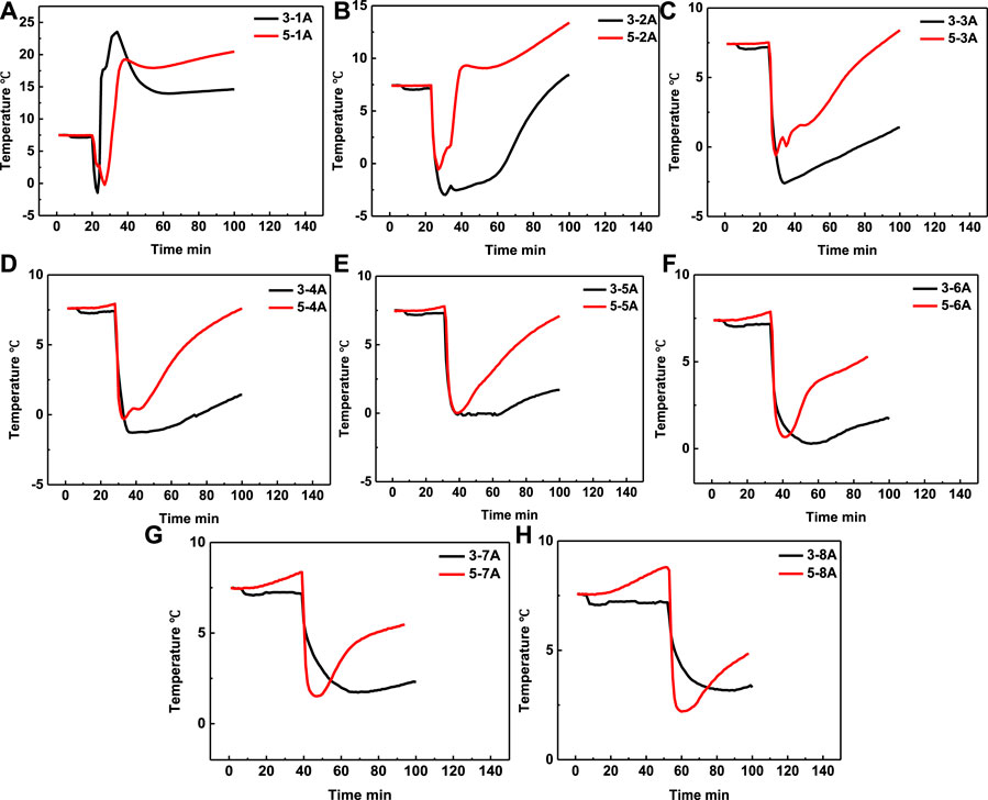
FIGURE 8. Temperature comparison in experiment 3 and experiment 5 at positon 1A (A), positon 2A (B), position 3A (C), position 4A (D), position 5A (E), position 6A (F), position 7A (G) and position 8A (H), respectively.
3.5 Effects of acid variety on the exothermic characteristics
The effects of acid variety on the heating range was investigated by experiment 6 and experiment 7. The acids used in this work were sulfamic acid and citirc acid. The effects of different acid variety on the temperature curve at different positions are shown in Figures 9A–D. The Figures 9A–H showed the temperature curves versus time at different positions. It can be seen that the temperature peak of the area near the injection entrance increase with the increase of the acidity, and the heating range is also increase with the increase of the acidity. Form Figures 9A–C, it can be seen that the temperature at position 1 catalyzed by 10 wt% sulfamic acid can reach 110°C, while the temperature at position 1 catalyzed by 10 wt% citric acid can only reach 50°C, which illustrated that the higher acidity was beneficial to increase the intensity degree of chemical reaction and the heat supply in the area near the entrance. The temperature at positions 2 and 3 all had a temperature peak. However, from Figures 9D–H, it can be seen that the temperature at position 4, 5, 6, 7, 8 was nearly did not increase in experiments 7, which may be because that the NaNO2 and NH4Cl was exhausted in the position 1, 2, and 3, and the reaction in the deeper area was very weak. In comparison, the lowest temperature at position 4–8 in experiments 7 is lower than that in experiment 6, which is because that the NaNO2 and NH4Cl was consumed less than that in experiment 7. The experiment results showed that the stronger acidity can increase the temperature near the entrance, while the weaker acidity can decrease the temperature decrease degree in a certain degree. This inspiring experimental results means that it is very probable to increase the energy supply capability of self-heating solution in the deeper area by carefully adjusting the action time between NaNO2 and NH4Cl.
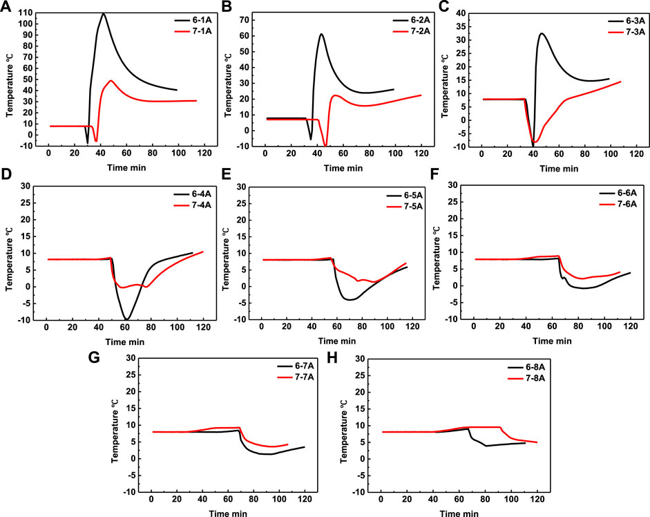
FIGURE 9. Temperature comparison in experiment 6 and experiment 7 at positon 1A (A), positon 2A (B), position 3A (C), position 4A (D), position 5A (E), position 6A (F), position 7A (G) and position 8A (H), respectively.
3.6 Effects of acid concentration on the heating range
In the same injection mode of mixed injection, the effect of acid concentration on the heating range is investigated by experiment 1 and experiment 2. The temperature comparison in experiment 1 and experiment 2 at positons 1A–8A were shown in Figures 10A–H, respectively. It can be seen that the temperature of position 1A increase with the increase of the acid concentration, which is because that the catalytic effect increased with the increase of acid concentration. It can be seen that the temperature in experiments 1 at position 1A, 2A, and 3A all has temperature peak, which means that the heating range of self-heating solution can cover these areas. In comparison, the temperature only at position 1A and 2A in experiments 2 has temperature peak, which means that the temperature only covered the 2A position. The experiments results mean that the heating range increased with the increase of acid concentration. The temperature of positon 4A–8A did not increase at all both in experiment 1 and 2, which means that the acid concentration also cannot send the energy to the deeper area.
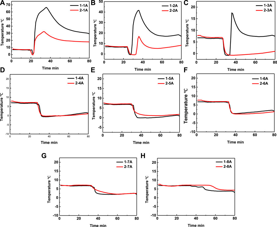
FIGURE 10. Temperature comparison in experiment 1 and experiment 2 at positon 1A (A), positon 2A (B), position 3A (C), position 4A (D), position 5A (E), position 6A (F), position 7A (G) and position 8A (H), respectively.
By experiment 4 and 5, we also studied the effect of acid concentration on the heating range area in the sectional injection mode. The temperature comparison in experiment 4 and experiment 5 at positons 1A–8A were shown in Figures 11A–H, respectively. It can be seen that when the acid concentration increased from 5 wt% to 10 wt%, the temperature at positon 1A, 2A, and 3A also increased with the increase of acid concentration, which is because that the chemical reaction became more acute. However, the temperature at positon 4A, 5A, 6A, and 7A in experiment 4 is lower than that in experiment 5, which is a very interesting phenomenon. By the experiments results, we can conclude that the acid concentration should have an optimal value, at which value the energy can be transported to deeper area.
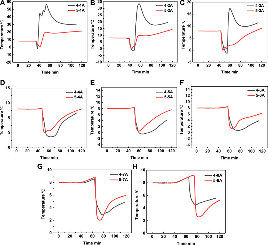
FIGURE 11. Temperature comparison in experiment 4 and experiment 5 at positon 1A (A), positon 2A (B), position 3A (C), position 4A (D), position 5A (E), position 6A (F), position 7A (G) and position 8A (H), respectively.
4 Conclusion and suggestion
In this work, the exothermic characteristics of self-heating solution include Na2NO2 and NH4Cl during the hydrate dissociation were investigated for the first time systematically. The effects of reagent concentration, the injection mode, acid variety and acid concentration on the heating range were studied with self-designed high pressure autoclave with 11.75 L. The experimental results showed that the temperature curve with self-heating solution is similar to that of conventional inhibitor injection. The temperature peaks near the entrance increased with the increase of reagents concentration, acidity, acid concentration, while the temperature far away from the entrance did not increase obviously with these influences factor, which means that these above factors cannot increase the energy supply in the area far away from entrance. The effect of injection mode also investigated in this work, and it can be seen from the experimental results that the sectional injection mode can decrease the temperature in the near area, while can increase the energy supply in the deep area far away from the entrance to a certain degree. The exothermic characteristics studies are very necessary to the thorough application of chemical self-heating solution in the exploitation of hydrate, and the studies in this work can lay the foundation of the further studies. In the end, two suggestions can be learned form the experimental results. First, the self-heating solution should be investigated in larger high-pressure autoclave to study the exothermic characteristics during the complex flowing process. Second, the accurate heat-supply adjustment method of self-heating solution should be investigated more deeply and systemically in the future study process.
Data availability statement
The original contributions presented in the study are included in the article/supplementary material, further inquiries can be directed to the corresponding authors.
Author contributions
XZ and DW carried out the experiments and wrote the first draft of the manuscript. BZ optimized the structure and tone of this manuscript. QY and SJ put foreard research ideas, contributed to the experimental design and supervised the whole process of the study. JZ helped a lot during the experiments. YW, ZW, JC and LL helped to carry out the experiments and contributed to the data reduction and article revision. All authors contributed to the manuscript and approved the submitted version.
Funding
This work is supported by the National Natural Science Foundation of China (No. 21978126).
Conflict of interest
Author BZ was employed by Jinan Noah Emergency Equipment Co., Ltd., and Author ZW was employed by Liaocheng Luxi Chemical Engineering Design Co.,Ltd.
The remaining authors declare that the research was conducted in the absence of any commercial or financial relationships that could be construed as a potential conflict of interest.
Publisher’s note
All claims expressed in this article are solely those of the authors and do not necessarily represent those of their affiliated organizations, or those of the publisher, the editors and the reviewers. Any product that may be evaluated in this article, or claim that may be made by its manufacturer, is not guaranteed or endorsed by the publisher.
References
Chen, J., Wu, J. J., Xu, J. F., Yuan, Q., Deng, B., Chen, C. Z., et al. (2020). Experiments and insights of desalination by a freezing/thawing method at low subcooling. Chin. J. Chem. Eng. 28, 3011–3017. doi:10.1016/j.cjche.2020.05.012
Chen, Y. H., Wang, X. M., Lang, S. S., and Fan, S. S. (2015). Energy-efficient methods for production methane from natural gas hydrates. J. Energy Chem. 24, 552–558. doi:10.1016/j.jechem.2015.08.014
Chuvilin, E., Valentina Ekimova, V., Davletshina, D., Bukhanov, B., Krivokhat, E., and Shilenkov, V. (2022). Temperature variation during salt migration in frozen hydrate-bearing sediments: Experimental modeling. Geosciences 12 (7), 261. doi:10.3390/geosciences12070261
Cranganu, C. (2009). In-situ thermal stimulation of gas hydrates. J. Pet. Sci. Eng. 65, 76–80. doi:10.1016/j.petrol.2008.12.028
Fan, S. S., Wang, X., Lang, X. M., and Wang, Y. H. (2017). Energy efficiency simulation of the process of gas hydrate exploitation from flue gas in an electric power plant. Nat. Gas. Ind. B 4, 470–476. doi:10.1016/j.ngib.2017.09.009
Feng, J. C., Wang, Y., Li, X. S., Chen, Z. Y., Li, G., and Zhang, Y. (2015). Investigation into optimization condition of thermal stimulation for hydrate dissociation in the sandy reservoir. Appl. Energy 154, 995–1003. doi:10.1016/j.apenergy.2015.05.106
Feng, J. C., Wang, Y., Li, X. S., Li, G., Zhang, Y., and Chen, Z. Y. (2015). Effect of horizontal and vertical well patterns on methane hydrate dissociation behaviors in pilot-scale hydrate simulator. Appl. Energy 145, 69–79. doi:10.1016/j.apenergy.2015.01.137
Hao, Y. M., Li, X. Z., Tao, S., Wei, X. L., and Liu, Y. Y. (2017). Heat conduction and convection of thermal front movement during natural gas hydrate heat injection exploitation. Nat. Gas. Ind. 37 (12), 47–52.
Hu, F. L., Yang, Y. H., Kang, M. Q., Chen, J., Liu, Q., Liu, J. H., et al. (2021). Hydrate-Based method to remove Cr(III) and Ni(II) in chromium hydroxide sulfate and nickel sulfate hexahydrate solutions. J. Chem. Eng. Data 66 (11), 4248–4253. doi:10.1021/acs.jced.1c00592
Jin, G. R., Xu, T. F., Xin, X., Wei, M. C., and Liu, C. L. (2016). Numerical evaluation of the methane production from unconfined gas hydrate-bearing sediment by thermal stimulation and depressurization in Shenhu area, South China Sea. J. Nat. Gas. Sci. Eng. 33, 497–508. doi:10.1016/j.jngse.2016.05.047
Kou, X., Feng, J. C., Li, X. S., Wang, Y., and Chen, Z. Y. (2022). Memory effect of gas hydrate: Influencing factors of hydrate reformation and dissociation behaviors. Appl. Energy 306, 118015. doi:10.1016/j.apenergy.2021.118015
Li, B., Liu, S. D., Liang, Y. P., and Liu, H. (2018). The use of electrical heating for the enhancement of gas recovery from methane hydrate in porous media. Appl. Energy 227, 694–702. doi:10.1016/j.apenergy.2017.08.066
Li, N., Zhang, J., Xia, M. J., Sun, C. Y., Liu, Y. S., and Chen, G. J. (2021). Gas production from heterogeneous hydrate-bearing sediments by depressurization in a large-scale simulator. Energy 234, 121183. doi:10.1016/j.energy.2021.121183
Li, S. X., Zheng, R. Y., Xu, X. H., and Hou, J. (2016). Energy efficiency analysis of hydrate dissociation by thermal stimulation. J. Nat. Gas. Sci. Eng. 30, 148–155. doi:10.1016/j.jngse.2016.02.005
Li, X. S., Wang, Y., Li, G., and Zhang, Y. (2012). Experimental investigations into gas production behaviors from methane hydrate with different methods in a cubic hydrate simulator. Energy fuels. 26 (2), 1124–1134. doi:10.1021/ef201641v
Liu, H., Mu, L., Wang, B., Liu, B., Wang, J., Zhang, X. X., et al. (2013). Separation of ethylene from refinery dry gas via forming hydrate in w/o dispersion system. Sep. Purif. Technol. 116 (15), 342–350. doi:10.1016/j.seppur.2013.06.008
Liu, M., Jiang, C. Y., Liu, Q. F., and Chen, J. (2019). Separation of C3H8 and C3H6 from butyl Alcohol−Octyl alcohol vent gas mixture via hydrate formation in the presence of SDS and THF in tap-water system. J. Chem. Eng. Data 64, 1244–1249. doi:10.1021/acs.jced.8b01129
Liu, S., Zhang, Y. Y., Luo, Y. J., Liang, Y. P., and Li, B. (2020). Analysis of hydrate exploitation by a new in-situ heat generation method with chemical reagents based on heat utilization. J. Clean. Prod. 249, 119399. doi:10.1016/j.jclepro.2019.119399
Liu, Y. L., Zhao, J. F., Yang, L., Li, Q. P., Wang, J. Y., and Wang, Y. L. (2019). Analyzing the process of depressurization-induced gas production from natural marine sediments. Energy Procedia 159, 5465–5471. doi:10.1016/j.egypro.2019.01.600
Ma, S. H., Zheng, J. N., Zhao, J., and Yang, M. G. (2021). Effects of temperature holding on methane hydrate decomposition process by thermal stimulation. J. Chem. Thermodyn. 159, 106487–106488. doi:10.1016/j.jct.2021.106487
Moridis, G. J., Collett, T. S., Pooladi-Darvish, M., Hancock, S., Santamarina, C., Boswell, R., et al. (2011). Challenges, uncertainties, and issues facing gas production from gashydrate deposits. SPE Reserv. Eval. Eng. 14 (1), 76–112. doi:10.2118/131792-pa
Mu, L., Li, X. L., Tan, Q. Q., Zhang, Q. Y., and Cui, Q. Y. (2022). Experimental study on CH4 recovery from simulated coal bed gas by forming hydrate slurries. Energy fuels. 36 (4), 1986–1995. doi:10.1021/acs.energyfuels.1c03691
Nair, V. C., Prasad, S. K., Kumar, R., and Sangwai, J. S. (2018). Energy recovery from simulated clayey gas hydrate reservoir using depressurization by constant rate gas release, thermal stimulation and their combinations. Appl. Energy 225, 755–768. doi:10.1016/j.apenergy.2018.05.028
Nair, V. C., Ramesh, S., and Sangwai, J. S. (2016). Influence of thermal stimulation on the methane hydrate dissociation in porous media under confined reservoir. J. Pet. Sci. Eng. 147, 547–559. doi:10.1016/j.petrol.2016.09.017
Song, Y. C., Kuang, Y. M., Fan, Z., Zhao, Y. C., and Zhao, J. F. (2018). Influence of core scale permeability on gas production from methane hydrate by thermal stimulation. Int. J. Heat. Mass Transf. 121, 207–214. doi:10.1016/j.ijheatmasstransfer.2017.12.157
Song, Y. C., Li, H. M., and Wang, Z. G. (2009). Study of natural gas production from hydrate with solar energy heating. J. Dalian Univ. Technol. 49 (6), 827–831.
Su, Z., He, Y., and Wu, N. Y. (2012). Numerical simulation on production potential of hydrate deposits by thermal stimulation. J. Trop. Oceanogr. 31 (5), 74–82.
Sun, Y. H., Jiang, S. H., Li, S. L., Wang, X. H., and Peng, S. Y. (2021). Hydrate formation from clay bound water for CO2 storage. Chem. Eng. J. 406, 126872. doi:10.1016/j.cej.2020.126872
Sun, Y. H., Zhang, G. B., Li, S. L., and Jiang, S. H. (2019). CO2/N2 injection into CH4+C3H8 hydrates for gas recovery and CO2 sequestration. Chem. Eng. J. 375, 1–12. doi:10.1016/j.cej.2019.121973
Wang, Y., Feng, J. C., Li, X. S., Zhang, Y., and Chen, Z. Y. (2018). Fluid flow mechanisms and heat transfer characteristics of gas recovery from gas-saturated and water-saturated hydrate reservoirs. Int. J. Heat. Mass Transf. 118, 1115–1127. doi:10.1016/j.ijheatmasstransfer.2017.11.081
Wang, Y., Feng, J. C., Li, X. S., and Zhang, Y. (2017). Experimental investigation of optimization of well spacing for gas recovery from methane hydrate reservoir in sandy sediment by heat stimulation. Appl. Energy 207, 562–572. doi:10.1016/j.apenergy.2017.06.068
Wu, J. J., Kang, M. Q., Hu, F. L., Yan, Y. H., Liu, C. Z., Chen, J., et al. (2021). Comparing hydrate-based method with freezing/thawing method for chromium hydroxide sulfate removal close to the melting point of ice. Sep. Purif. Technol. 266, 118523. doi:10.1016/j.seppur.2021.118523
Xie, Y., Zhu, Y. J., Zheng, T., Yuan, Q., Sun, C. Y., Yang, L. Y., et al. (2021). Replacement in CH4-CO2 hydrate below freezing point based on abnormal self-preservation differences of CH4 hydrate. Chem. Eng. J. 403 (126283), 126283. doi:10.1016/j.cej.2020.126283
Yang, L., Liu, Y. L., Zhang, H. Q., Xiao, B., Guo, X. W., Wei, R. P., et al. (2019). The status of exploitation techniques of natural gas hydrate. Chin. J. Chem. Eng. 27, 2133–2147. doi:10.1016/j.cjche.2019.02.028
Yang, M. J., Ma, Z. Q., Gao, Y., and Jiang, L. L. (2019). Dissociation characteristics of methane hydrate using depressurization combined with thermal stimulation. Chin. J. Chem. Eng. 27 (9), 2089–2098. doi:10.1016/j.cjche.2019.02.008
Yang, X., Sun, C. Y., Su, K. H., Yuan, Q., Li, Q. P., and Chen, G. J. (2012). A three-dimensional study on the formation and dissociation of methane hydrate in porous sediment by depressurization. Energy Convers. Manag. 56, 1–7. doi:10.1016/j.enconman.2011.11.006
Yu, T., Guan, G. G., Abudula, A., Yoshida, A., Wang, D. Y., and Song, Y. C. (2019). Heat-assisted production strategy for oceanic methane hydrate development in the Nankai Trough, Japan. J. Pet. Sci. Eng. 174, 649–662. doi:10.1016/j.petrol.2018.11.085
Yuan, Q., Sun, C. Y., Liu, B., Wang, X., Ma, Z. W., Ma, Q. L., et al. (2013). Methane recovery from natural gas hydrate in porous sediment using pressurized liquid CO2. Energy Convers. Manag. 67, 257–264. doi:10.1016/j.enconman.2012.11.018
Yuan, Q., Sun, C. Y., Wang, X. H., Yang, X., Liu, B., Ma, Z. W., et al. (2013). Experimental study of gas production from hydrate dissociation with continuous injection mode using a three-dimensional quiescent reactor. Fuel 106, 417–424. doi:10.1016/j.fuel.2012.12.044
Yuan, Q., Sun, C. Y., Yang, X., Ma, P. C., Ma, Z. W., Li, Q. P., et al. (2011). Gas production from methane-hydrate-bearing sands by ethylene glycol injection using a three-dimensional reactor. Energy fuels. 25 (7), 3108–3115. doi:10.1021/ef200510e
Yuan, Q., Sun, C. Y., Yang, X., Ma, P. C., Ma, Z. W., Liu, B., et al. (2012). Recovery of methane from hydrate reservoir with gaseous carbon dioxide using a three-dimensional middle-size reactor. Energy 40, 47–58. doi:10.1016/j.energy.2012.02.043
Zeng, H. P., Zhang, Y., Li, X. S., Chen, C., Zhang, L., and Chen, Z. Y. (2022). Experimental study on the influence of brine concentration on the dissociation characteristics of methane hydrate. J. Nat. Gas. Sci. Eng. 100, 104492. doi:10.1016/j.jngse.2022.104492
Zeng, Y. S., Chen, J., Yu, X. G., Wang, T., Deng, B., Zeng, F. H., et al. (2020). Suppression of methane hydrate dissociation from SDS-dry solution hydrate formation system by a covering liquid method. Fuel 277, 118222. doi:10.1016/j.fuel.2020.118222
Zhang, W. D., Liu, Y. J., Ren, S. R., and Wang, R. H. (2008). Thermal analysis on heat injection to natural gas hydrate (ngh) recovery. Nat. Gas. Ind. B 28 (5), 77–79.
Zhao, J. F., Fan, Z., Wang, B., Dong, H. S., Liu, Y., and Song, Y. C. (2016). Simulation of microwave stimulation for the production of gas from methane hydrate sediment. Appl. Energy 168, 25–37. doi:10.1016/j.apenergy.2016.01.091
Zhao, J. F., Wang, J. Q., Liu, W. G., and Song, Y. C. (2015). Analysis of heat transfer effects on gas production from methane hydrate by thermal stimulation. Int. J. Heat. Mass Transf. 87, 145–150. doi:10.1016/j.ijheatmasstransfer.2015.04.007
Zhao, J., Yang, L., Liu, Y., and Song, Y. (2015). Microstructural characteristics of natural gas hydrates hosted in various sand sediments. Phys. Chem. Chem. Phys. 17, 22632–22641. doi:10.1039/c5cp03698d
Zheng, R. C., Chan, A. H. M., Babu, P., Yang, M. J., and Linga, P. (2015). Effect of NaCl on methane hydrate formation and dissociation in porous media. J. Nat. Gas. Sci. Eng. 27, 178–189. doi:10.1016/j.jngse.2015.08.055
Keywords: hydrate, thermal stimulation, self-heating solution, exothermic characteristics, in situ thermal stimulation
Citation: Zheng X, Wu D, Zhou B, Wang Z, Liu L, Yu J, Yuan Q, Jiang S, Zhao J and Wang Y (2022) Exothermic characteristics research of chemical self-heating solution in the gas hydrate exploitation process. Front. Energy Res. 10:1049360. doi: 10.3389/fenrg.2022.1049360
Received: 20 September 2022; Accepted: 25 October 2022;
Published: 07 November 2022.
Edited by:
Jun Chen, Xiangnan University, ChinaReviewed by:
Liang Mu, Fuzhou University, ChinaBohui Shi, China University of Petroleum, Beijing, China
Copyright © 2022 Zheng, Wu, Zhou, Wang, Liu, Yu, Yuan, Jiang, Zhao and Wang. This is an open-access article distributed under the terms of the Creative Commons Attribution License (CC BY). The use, distribution or reproduction in other forums is permitted, provided the original author(s) and the copyright owner(s) are credited and that the original publication in this journal is cited, in accordance with accepted academic practice. No use, distribution or reproduction is permitted which does not comply with these terms.
*Correspondence: Qing Yuan, eXVhbnFpbmdAbGN1LmVkdS5jbg==; Song Jiang, amlhbmdzb25nMDA2QDE2My5jb20=