 Xin Yao
 Guangtai Shi
 Haigang Wen1,2
- 1Key Laboratory of Fluid Machinery and Engineering, Xihua University, Chengdu, China
- 2Key Laboratory of Fluid and Power Machinery, Xihua University, Ministry of Education, Chengdu, China
With the exploitation of deep sea and desert oil fields, multiphase pumps have come into the public eye. However, due to the nature of the medium and operating environment, the performance of traditional multiphase pumps has diminished, leading to problems such as increased recovery cycles and rising costs. In order to obtain a high-head, high-reliability multiphase pump, this paper uses the model optimization method to design a complex pattern impeller. The best complex impeller with 17.25% increase in head was selected with the external characteristics as the optimization index, and a comparative analysis of the internal flow field was carried out between the complex impeller and original impeller when the inlet gas volume fraction was 10%. The results show that in the complex impeller, the short blade reduced the proportion of the high-speed zone, inhibited the appearance of the main blade suction surface low-speed zone, and significantly improved the return flow. The slope of the pressure boosting curve at the relative position 1.5–2.0 was increased, and the pressure boosting capacity was increased by 16.34 kPa. The short blade weakens the leakage movement while reducing the pressure effect on the main blade. In addition, the short blade not only improved the gas phase gathering but also reduced its size and made it closer to the main blade suction surface, which improved the uniformity of the gas phase distribution in the flow channel and also enhanced the inlet flow capacity. The results can provide a reference for future optimization and performance improvement of multiphase pump models.
1 Introduction
With the development and use of oil fields in deep sea and desert areas, the use of multiphase pumps as the core equipment of mixed transport extraction, owing to their compact structure, easy disassembly, and the ability to transport multiphase media, is becoming increasingly prominent (Williams et al., 2018; Zilong et al., 2020). Compared with the traditional oil and gas extraction technology, multiphase pumps can meet the oil and gas extraction and transmission by laying a pipeline and are not easily restricted by the site and when installed are favored by industry users (Yi et al., 2018). However, in practice, multiphase pumps are affected by the different nature of the transported medium, the special structure of multiphase pumps, and their working environment. The multiphase pump’s internal flow is often complicated and variable, thus causing the deterioration of the flow pattern and resulting in the degradation of the mixing performance (Jianwei et al., 2021; Guangtai et al., 2022). As a result, the recovery cycle increases, oil and gas field production decreases, operation and maintenance costs increase and many other problems (Guangtai et al., 2020a), so it is extremely important to optimize the multiphase pump to obtain high head and high reliability of the recovery performance.
Impeller as the main pressurization unit converts the motor input energy into pressure energy to the medium. Its hydraulic performance has a significant impact on the multiphase pump (Guangtai et al., 2020b). Due to the rotation of the impeller, its internal flow pattern is often complex and changeable. In the meantime, to prevent the impeller blade and impeller shroud scraping, there is a small amount of space between the two that is named tip clearance (Zekui et al., 2022a). The existence of tip clearance leads to leakage flow at the top of the impeller, which has a greater impact on the flow in the flow channel of the multiphase pump, especially to reduce the pump head (Qiang et al., 2016; Zekui et al., 2022b). Combining the above factors, the focus and difficulty of optimizing multiphase pumps lies in optimizing the flow pattern within the impeller.
At present, there are two main aspects of impeller optimization methods for rotating machinery, one is internal flow optimization and the other is model design optimization (Suh et al., 2017), and a large number of studies have been reported. Liu et al. Ming et al. (2018) used orthogonal optimization to rank the influence of four main factors on the impeller blades of a multiphase pump, discovered that optimized pump pressure increased by 12.8 kPa and improved the gas volume fraction and pressure distribution in the pump. Zhang et al. Jinya et al. (2009) also used this method to improve the pressurization performance of a multiphase pump. In addition to orthogonal optimization, there also appeared the improved computational equation optimization methods. Li et al. Jia et al. (2022) used the improved Bezier curve for the optimization of the centrifugal pump impeller, which reduced flow losses and made flow patterns better, thus forming smoother internal pressure distribution. Ye et al. Weixiang et al. (2021) optimized the SST k-ω partly averaged Navier–Stokes calculation equations for a study of a mixed-flow pump and found that the optimized equations could change the blade loading mode from medium load to front load, the hump area is moved to a deeper partial. As optimization research methods continue to improve, there are also studies that combine multiple optimization methods simultaneously. For example, the combination of controlled velocity moment and orthogonal optimization can make an optimized impeller with 23.1% smaller dominant frequency amplitude, 11.9 kPa higher pressure and 3.6% higher efficiency than the reference impeller, while suppressing dynamic and gas-hydraulic interference in the pump (Xianwei et al., 2019; Wenyang and Lei, 2021). Wang et al. Mencheng et al. (2021) combined artificial neural networks with genetic algorithms to optimize the impeller of a mixed-flow pump and found that it significantly increased the axial velocity near the impeller outlet hub, which removed more of the low-momentum fluid. It was also discovered that the pressure difference between the suction surface of the impeller and the hub at the impeller outlet was reduced, which prevented backflow.
In the aspect of model design optimization, scholars have proposed different kinds of optimization methods such as remodeling blade shape, slotting drainage, and changing blade number. Tan et al. Lei et al. (2018) conducted a study on a mixed-flow pump with T-shape blade and found that T-shape blade not only reduced leakage of tip clearance and improved flow pattern in tip clearance region of impeller but also promoted the efficiency. Liu et al. Yabin and Lei, (2018) applied a C groove on a NACA0009 hydrofoil and discovered that C groove suppressed the vortex and leakage and avoided the direct impact of gas inlet flow from main flow to the groove. Shi et al. Yi et al. (2019) found that split blade impeller effectively suppressed gas aggregation in the multiphase pump flow channel, improved the flow, and made separate gas–liquid mix again on the suction side of the blade. Namazizadeh et al. (2020) studied the influence of short blades’ length and position on centrifugal pump impeller and discovered that when length was 66% total head increased by 10.6% and efficiency reduced as friction losses increased. Moving the short blade along the direction of impeller rotation direction can increase the centrifugal pump’s efficiency as the short blade better guides the flow near the suction side of the main blade. Xu et al. Yun et al. (2019) increased the number of multiphase pump impeller blade and found that the control effect on the flow pattern in the downstream region of impeller was stronger and that the pressure fluctuation was weakened. Shi et al. Guangtai et al. (2020c) compared the number of impeller blade and found that only when blade number was 4, the pressure changed more uniformly and the medium pressurization effect was better. In addition, the gas–liquid separation in a multiphase pump at high gas volume fraction was the main reason for its performance decline. Zhang et al. Jinya et al. (2012) contrasted remodel blade shape slot drainage and change blade number three methods found that all improved the distribution of liquid phase streamline enhanced the gas–liquid mixing degree and lifted impeller pressurization performance.
Through the abovementioned references, we discovered that a great deal of research achievements have been made in internal flow optimization on multiphase pump impeller. In contrast, in the model optimization field, most research focused on remodeling blade shape and slotting optimization. A few articles were based on considering tip clearance to study the influence of relevant design parameters after adding blades on the external characteristics and internal flow field on the multiphase pump. Therefore, this paper considers tip clearance with the goal of optimizing the head design, a complex impeller, by adding short blades at the self-developed multiphase pump’s impeller and studied the flow field changes in the multiphase pump before and after complex pattern. This study provides references for the future model design optimization on the multiphase pump.
2 Research model and computational domain
In this paper, a self-developed multiphase pump was selected as the research model, and Table 1 shows its main design parameters. As for computational domain, pressurization unit impeller and diffuser were taken as the main research objects. To ensure sufficient flow, UG software was used to draw the inlet and outlet extension section and the length was 3.2 and 5.7 times of axial length of impeller, respectively. The whole units consisted of an inlet extension section, outlet extension section, impeller, and diffuser. For ease of description, the dimensionless position parameter radial coefficient r* was introduced and defined. As the impeller and diffuser were normalized from impeller or diffuser’s hub to its shroud along the radial direction. The hub position was zero and the shroud was one. Along flow direction, the inlet to outlet position was expressed by the flow direction coefficient 0–4. The overall calculation domain is shown in Figure 1, and the local amplification diagram shows the tip clearance position.
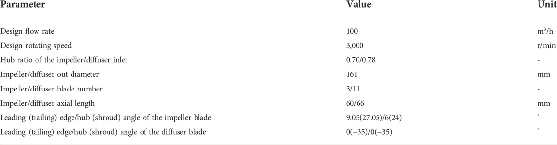
TABLE 1. Main performance parameters of the multiphase pump.

FIGURE 1. Simplified model of the computational domain.
3 Research method
3.1 Multiphase model and control equation
The multiphase flow models are divided into a mixed model, VOF model, and Eulerian model. The mixed model is suitable for multiphase fluids with different velocity in different mediums. The VOF model is used for studying separation characteristics of medium and predicting steady and transient treatment of gas–liquid interface. The Euler model is applied to multiphase separation flow and multiphase flow with interphase force, which is not affected by medium properties. Therefore, the Euler model is chosen to simulate multiphase flow in this paper. The continuity equation and momentum equation are as follows:
Continuity equation:
Momentum equation:
Here, i, j, α, φ, ρ, and g denote the liquid phase, gas phase, volume fraction, interphase velocity (m/s), medium density (kg/m3), and gravity acceleration (m/s2); mij represents mass transfer from phase i to j; mji is on the contrary; Si is the source term of itself; τi is the pressure strain tensor of i phase; Ei is the momentum change of mass transfer between phases; Fi is the interphase force (external volume force, lift force, and virtual mass force).
3.2 Boundary conditions
Numerical simulation for multiphase pump was conducted by ANSYS CFX, the rated flow rate was 100 m3/h, and the k-ε turbulence model was used in single-phase flow. In the as–liquid two-phase flow, the SST k-ω turbulence model was used for liquid (water) and the zero equation was used for gas (air). Then set water and air as continuous and dispersed phase in turn, and bubble diameter set to 0.2 mm. Impeller as a rotating domain rotated counterclockwise around flow direction and speed was 3,000 r/min, the other units being static domain, and the dynamic and static interface was “Frozen Rotor”. The inlet velocity was 2.689 m/s (based on design flow divided by area) and outlet static pressure was 7 atm. The solid wall boundary was a non-slip and the default “Automatic” wall function boundary was used in the near wall region. The “RMS” scheme was selected to converge and the convergence accuracy was set to 10–5. The first-order upwind difference scheme was used for single-phase and the second-order upwind was used for two-phase.
3.3 Model optimization method
Ansys BladeGen software was used to design SB, click the “Add short” under the “Blade” plate and modify the “LE (leading edge)/TE (trailing edge) cut-off” parameter to set length value β. Then set the circumferential offset angle λ in “Location”. In order to study SB’s length and position influence on the flow field in multiphase pump, parameter β was introduced to measure SB length, which was defined as the SB length divided by MB (main blade) length. Parameter λ represented SB position, which was defined as the MB and SB center angle divided by the two MB center angle (the center angle of the two MB of the self-developed model was 120°), as shown in Figure 2. Design two β values (β1 = 0.4 and β2 = 0.5), three λ values (λ1 = 0.3, λ2 = 0.45 and λ3 = 0.6), and other structural parameters remain unchanged. Six complex impellers were designed by every β and λ combination and named as Case 1 ∼ Case 6 in turn. For ease description, PS represented the blade pressure surface, SS represented the suction surface. The flow channel between MBSS and SBPS was named A, and between SBSS and MBPS named B. The model and the corresponding blade profile are shown in Figure 3.
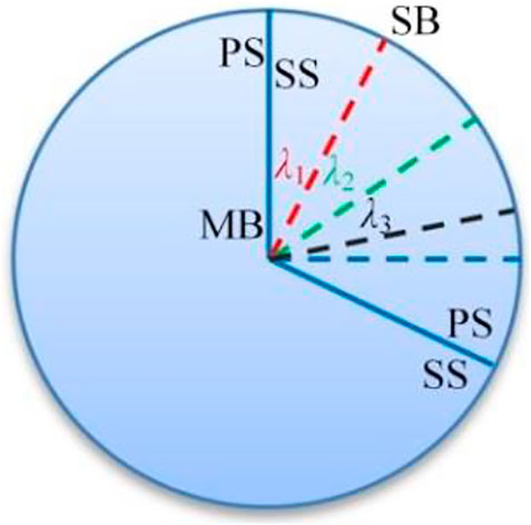
FIGURE 2. Blade position diagram.
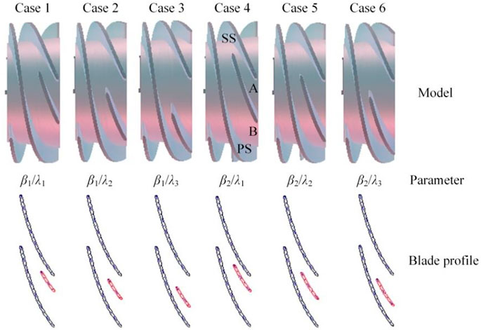
FIGURE 3. Complex impeller model.
3.4 Grid division and independence verification
Complex impeller directly imported into TurboBid software for structured grid division of single channel for 1-mm tip clearance impeller and diffuser in turn. ICEM Surf software was used to conduct structured grid division for inlet and outlet extension section. Finally, in CFX preprocess, rotating pressurization unit single channel rotated into a full channel and integrated with the grid of inlet and outlet extension section to consist of the overall computational domain grid. The grids of the original impeller, Case 1 impeller, and diffuser are shown in Figure 4, separately.
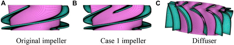
FIGURE 4. Grid division of pressurization unit. (A) Original impeller. (B) Case 1 impeller. (C) Diffuser.
To ensure numerical calculation results were not affected by grids number, five sets of grids were selected to calculate original impeller under water single-phase condition and the grid independence was verified. As shown in Table 2, with the increase in grid number, the head and efficiency increased and tend to be stable. Only a little difference in the head and efficiency between the fourth and fifth so the influence on the calculation results can be ignored. Consider the hardware configuration and calculation time, the fourth set of grids was selected for further research. The inlet and outlet grid number was 1180932, original impeller was 739716, and diffuser was 1171170. Due to the presence of SB so controlled the grid number of complex impeller was larger than original impeller to ensure the calculation accuracy.
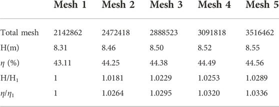
TABLE 2. Grid independence verification.
4 Results and analysis
4.1 Complex pattern influence on external characteristics
According to the numerical simulation results, the head, hydraulic efficiency, and total efficiency of the multiphase pump were calculated as follows:
In Eq. 3, H is the head, m; Pout and Pin are the outlet and inlet total pressure, Pa. In Eq. 4, η1 is hydraulic efficiency; Q is the design flow, m3/s; M is impeller torque, N•m; ω is rotational speed, rad/s. In Eq. 5, η2 is mechanical efficiency 92%; η3 is volumetric efficiency 84%.
The test bench is shown in Figure 5. The head of original impeller was measured by using this equipment when water single-phase condition was 8.09 m and the total efficiency was 33.71%. From the numerical simulation data of external characteristics in Table 3 the simulation head was 8.52 m and the total efficiency was 34.38%. Based on Eq. 5, the relative deviations of experiment and simulation were 5.32% and 1.99%, respectively. It was indicated that the numerical simulation method can be used to analyze the performance of the complex impeller (Figure 5B 1–14: water tank, water pump, flow meter, outlet valve, inlet valve, motor, torque meter, gas–liquid mixing tank, outlet pressure gauge, inlet pressure gauge, multiphase pump, gas valve, air compressor, and rotameter).
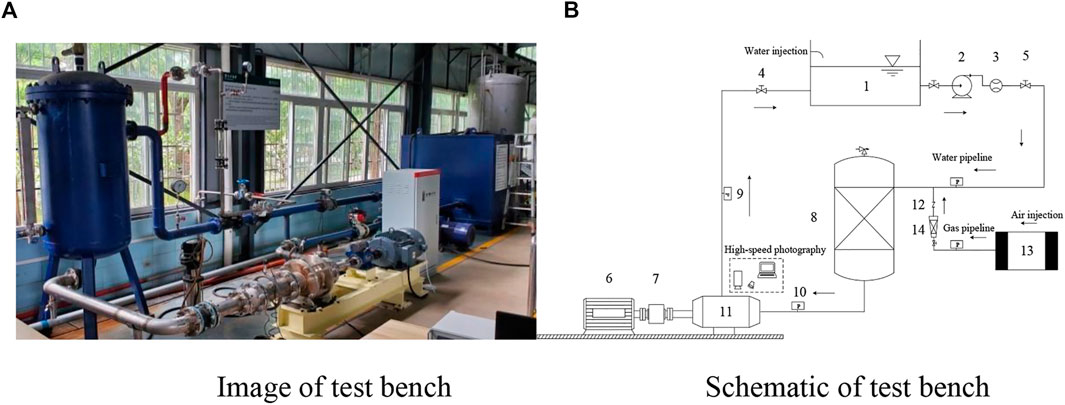
FIGURE 5. Experimental system. (A) Image of test bench. (B) Schematic of test bench.
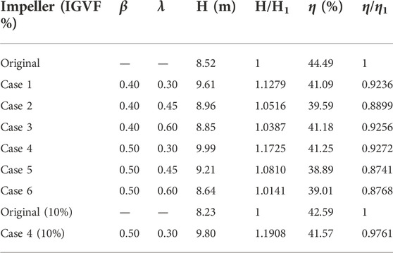
TABLE 3. External characteristics of the original and complex impeller.
From Table 3, it can be discovered that multiphase pump head was significantly improved after complex. SB induced an increase in friction loss and a decrease in hydraulic efficiency. Take Case 1–3 and Case 4–6 compare with original impeller, respectively, to analyze λ value of SB on external characteristics influence. Under the same β value, with λ value increased the complex impeller head increased first and then decreased, the hydraulic efficiency decreased sharply when λ was 0.45. The reason is that the layout of SB failed to balance the flow in the two sides of the flow channel. Thus resulting flow separation in the impeller channel. Then vortex structure appeared and the flow loss increased. The original impeller had a local low-speed area on MBPS (Guangtai et al., 2021). When the λ value was 0.30 offset a certain angle and made SB close to MBSS, let the area of channel A smaller than B. Thus, both sides of the SB had a balance flow in channel that could reduce some flow loss. So, the λ value of 0.3, namely, for Case 1 and Case 4 were reasonable. Comparing Case 1, Case 4, and the original impeller found that when the β value was 0.5 the head was higher than 0.4 and the hydraulic efficiency had a smaller decrease. Meanwhile, due to SB with 0.5 length made the flow separation of the medium in the channel ahead of time so that water-phase get better uniform mixing after separation at the SB before flow out of complex impeller. Therefore, after comprehensive analysis of external characteristics, it is found that Case 4 can balance the flow in the flow channel and improve the multiphase pump’s head greatly, so selected Case 4 as the best complex impeller and made it analyze with original impeller under the condition of IGVF was 10% in the next.
4.2 Complex impeller influence on internal flow characteristics
Along the flow direction, three sections (P1 ∼ P3) were cut on impeller from MBLE to MBTE. One axial surface was taken every 13° along the rotation direction of impeller named S1 ∼ S9 in turn. Also, dividing the axial surface, the E region was the tip clearance and the F was the axial surface of the impeller channel as shown in Figure 6.
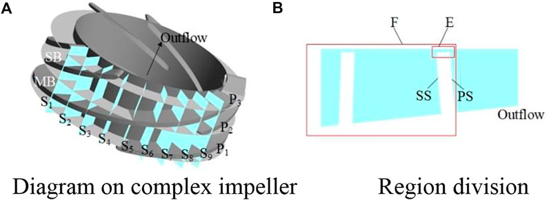
FIGURE 6. Diagram of the section and axial surface. (A) Diagram of the complex impeller. (B) Region division.
4.2.1 Complex pattern influence on velocity distribution
Liquid velocity contour and streamline distribution on each section of the impeller before and after complex pattern are shown in Figure 7. It can be seen that the maximum liquid velocity areas moved from shroud to hub along the flow direction (P1 to P3). At the same time, when gas–liquid phase flowed through the blade LE it hits the MBPS, causing the fluid flow angle (the angle between relative and circumferential velocity) and the blade inlet angle difference induced the maximum velocity to appear near the MBPS on P1. After complex, the P1 was not influenced by the SB. On P2, the emergence of SB narrowed the flow area in channel A, resulting in maximum velocity areas mainly aggregation in the channel A and low velocity areas increased in the channel B. Furthermore, due to flow separation occurring on P2, the flow instability made the velocity distribution on P2 of complex impeller uneven. On P3, the MBSS of original impeller had a few low-speed areas. However, it gradually disappeared after complex, and the proportion of the high-speed areas on the whole section decreased. Meanwhile, gas–liquid phase separated from P2 through the SB that had fully mixed flow obtained uniform distribution on P3. Compared streamline of every section, except for on P2 affected by SB diffluent appeared vortex caused unstable flow, the other section flows were smooth. In summary, the influence of complex impeller SB on velocity was mainly concentrated in the middle flow separation stage and the flow channel AB.
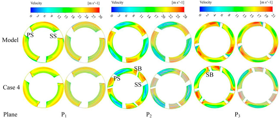
FIGURE 7. Liquid velocity distribution on the section before and after complex pattern.
Figure 8 displays velocity contour and vector of impeller outlet at different blade heights before and after complex pattern. From original impeller outlet velocity vector discovered that because of inconsistency between impeller fluid flow angle and blade outlet angle, on MBPSLE have occurred outflow, the velocity vector was denser. As radial coefficient increased, gas-liquid phase separation enhanced, vector distribution near MBSS became sparse and uneven. A large low-speed areas near MBSSTE occurred, based on velocity vector discovered that vector arrow pointed to income flow direction on this area explained the generation of backflow. After complex, velocity speed in channel A increased affected by SB and low-speed areas reduced. Concomitantly, the extrusion between the MB and SB enhanced then leads to gas–liquid phase flow close to MBSS, which weakened the backflow at MBLE. As radial coefficient increased, vector distribution was still uniform when r* = 0.5, it was suggested that SB improved the mixing degree of gas-liquid phase. While, noteworthy that there was a velocity vector obviously aggregated into strips at r* = 0.9. Through observation it was found that this was formed by the inhibition of partial backflow by SB, which made the split gas–liquid phase move towards the SBPS ahead of time after accelerating in channel A.
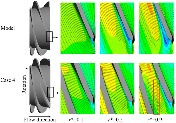
FIGURE 8. Velocity contour and vector of the impeller outlet before and after complex pattern.
4.2.2 Complex pattern influence on pressurization performance
The pressurization performance was a key indicator to reflect internal flow field change and measure multiphase pump performance. Figure 9 displays the static pressure distribution of multiphase pump from inlet to outlet along flow direction. From Figure 9, it can be seen that the impeller before and after complex pattern were the main pressurization component. After complex the diffuser transform kinetic energy into pressure energy ability was shown. From the data it was discovered that the maximum pressure difference of original impeller was 100.16 kPa, after complex was 116.5 kPa, pressurization performance increased by 16.34 kPa. The main presented as the inlet pressure reduced the outlet pressure remained constant. Simultaneously, due to dynamic interference and static interference, there is an obvious impact on the loss of the impeller inlet blade LE. At the same time, the flow separation, the leakage flow in tip clearance and the pressure at the interface of the impeller fluctuated greatly. Moreover, at the relative position of 1.5–2.0, because of SB the slope of the pressurization curve k2 was bigger than k1, revealed pressurization performance was enhanced after complex.
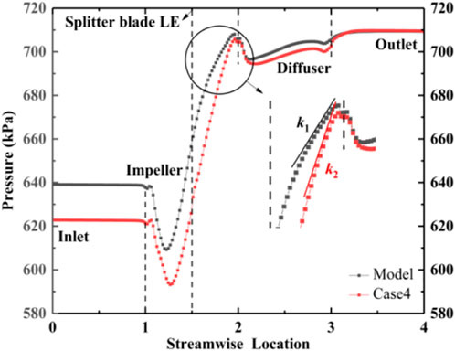
FIGURE 9. Static pressure distribution.
In order to further reveal SB influence the pressure change on impeller blade, Figure 10 shows the static pressure distribution on impeller blade surface. The colored region represented the pressure load of the blade (the static pressure of the blade PS minus SS was defined as positive, on the contrary as negative). It can be seen that the two impellers MBSSLE and complex impeller SBSSLE pressure were higher than its PS, which illustrated that the pressure load was negative. Also, it was not conducive to multiphase pump work, after complex the phenomenon continued to the relative position 1.2 after on MB. However, from the fluctuation range of pressure difference in colored area, after complex affected by SB the MB fluctuation of static pressure on blade surface was smaller than original impeller. At the same time, the MB of original impeller has a large blade pressure load at the relative position about 1.4. After complex, superimposed the MB and SB pressure loads, the relative position of large blade pressure loads region moved to complex impeller outlet. Along the flow direction, it can be observed that the pressure on MB surface of the two impellers increased gradually and the pressure on SS decreased first then increased due to the leakage of tip clearance. In the region of relative position 1.6, gas–liquid phase took place unstable flow due to SB diversion, resulting in pressure fluctuation during the increase on complex impeller MBSS. In addition, the narrowed flow channel A caused the pressure of SBPS to decrease in the region of relative position 1.8 on complex impeller, and the pressure of SS gradually increased due to the proportion of high-speed areas decreased.

FIGURE 10. Surface static pressure distribution.
According to SB length and position selected E region on axial surface S5 ∼ S9 display the tip clearance pressure distribution in Figure 11. From Figure 11, it can be found that the high-pressure areas in tip clearance of two impellers were mainly distributed on MBPS side and the low-pressure areas distributed on MBSS side. From the pressure difference discovered that the leakage motion in tip clearance was from MBPS to MBSS. On original impeller S5 ∼ S6, the low-pressure areas accounted for a large proportion, only on MBPS appeared a small high-pressure areas. After complex, the high-pressure areas on S5 ∼ S6 gradually disappeared and the low-pressure areas expanded, which indicating that the pressure difference in tip clearance decreased and the leakage motion was weakened. On S7, the low-speed areas on the original impeller began to decrease, the pressure gradient was smaller than S5 ∼ S6 and continued to S9. After complex, large low-pressure areas still on S7 and a small amount of high-pressure areas appeared on MBPS, the pressure gradient increased compared with S5 ∼ S6 and the increase trend was more obvious on S8. Because SB just appeared caused diffluent and pressure fluctuations, then gas–liquid phase and leakage flow mixing formed unstable flow, resulting pressure gradient changed. In the meantime, after diffluent gas–liquid phase also farther flow and mix in both A and B channel made the local low-pressure areas disappear on S9 and a decrease in pressure gradient. It was suggested that SB made the main pressurization position move backward from S5 ∼ S6 of the original impeller to S7 ∼ S8 of the complex impeller, and weakened the leakage movement on MBLE.
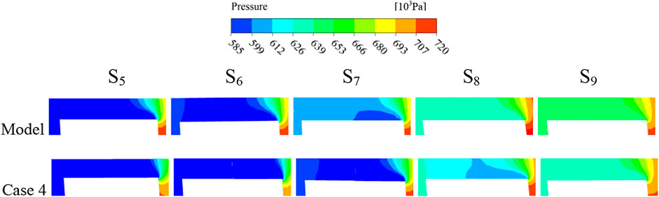
FIGURE 11. Pressure distribution of S5 ∼ S9 on the E region before and after complex pattern.
4.2.3 Complex pattern influence on gas phase distribution
The uniform distribution of gas–liquid phase was conducive to improve the conveying performance of multiphase pump. However, under the centrifugal force the gas–liquid phase with density difference was prone to cause separation in the impeller and resulting in gas aggregation. Then the formation of gas clusters to deteriorate the flow pattern in the channel. In order to analyze the influence and variation law of SB on gas mass aggregation in the impeller channel before and after complex pattern, the strongest point of gas mass was picked up on each section to represent the central point of gas mass aggregation on section. Connect each central point formed a line approximated as the trajectory gas mass aggregation as shown in Figure 12. From Figure 12A, it can be found that after gas–liquid phase entered the original impeller channel it formed aggregated gas masses and close to MBLESS. In the process of moving along MB profile to MBTE in channel, the central point gradually moved away from MBSS due to the enhanced effect of tip clearance leakage flow and gas–liquid phase separation. Furthermore, moving downstream, the central point approached the adjacent of MBPS. At the same time, due to the pressure difference fluctuation of the blade and the special channel structure influence, the gas mass aggregation trajectory fluctuates.
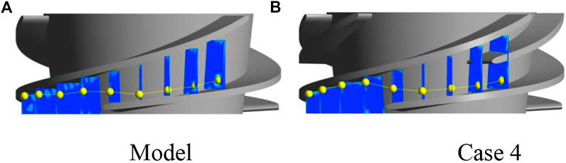
FIGURE 12. Trajectory of gas mass aggregation. (A) Model. (B) Case 4.
After complex, gas mass still gathered at MBSSLE, when along blade profile moved backward, affected by SB diffluent fluctuation, the central point continuously moved to MBSS as shown in Figure 12B. With leakage and diffluent enhanced, the central point mutation occurred on S4 ∼ S5, the gas masses position moved from MBSS to the adjacent of MBPS. After approaching it was kept on MBPS and moved downstream. This explained that the existence of SB affected the location and trajectory of gas mass aggregation in impeller channel. Simultaneously, because where gas mass formed there was vortex generated, it also explained why SB has an effect on vortex distribution.
Figure 13 shows the gas distribution on each axial surface of impeller before and after complex pattern. It can be seen that on S1 ∼ S3 smaller sized gas masses with greater intensity were formed close to the original impeller shroud and many gas masses with less intense were scattered throughout the channel. On S4, affected by the enhanced leakage, the gas phase moved from MBPS to the channel of MBSS through tip clearance, then connected with greater intensity small-size gas masses. In the process of moving backwards along the MB profile on S5 ∼ S9, due to mixing flow between leakage flow in tip clearance and gas–liquid phase in channel, the degree of complex flow pattern and gas phase aggregation became stronger, the size of gas masses aggregation in channel became larger that made gas masses approached the adjacent of PSMB from the middle of the channel. In addition, close to original impeller S8 ∼ S9, a large amount of gas gathered on MBSS caused gas–liquid phase detachment flow from blade surface that deteriorated flow pattern in original impeller outlet and decreased the conveying performance of multiphase pump.
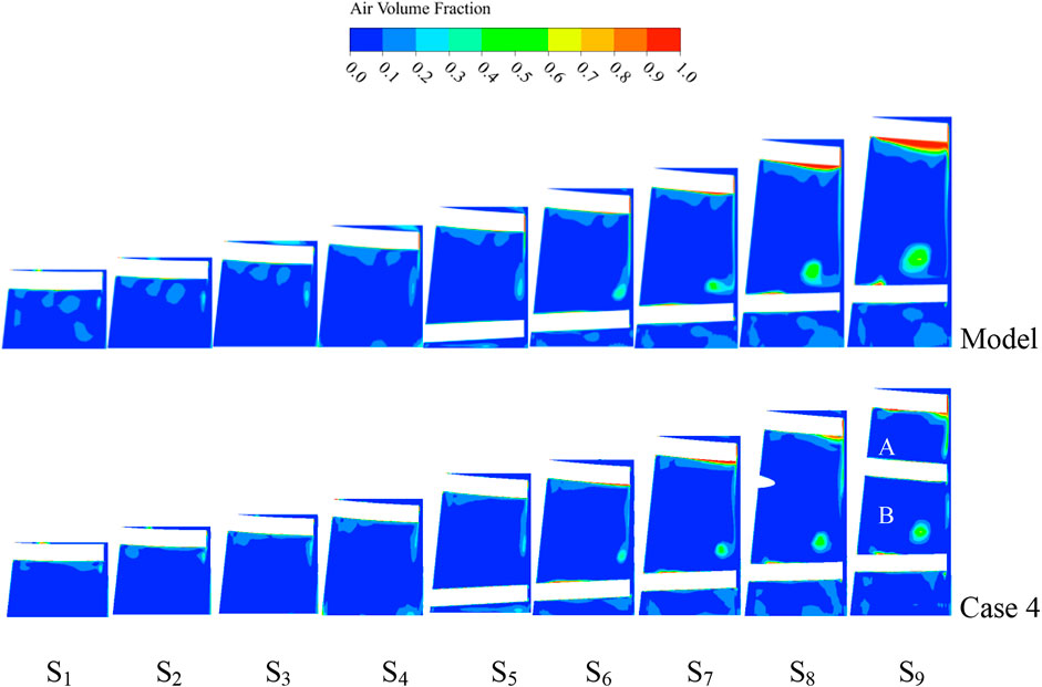
FIGURE 13. Gas distribution on S1 ∼ S9 of the F region before and after complex pattern.
After complex, the greater intensity gas masses on S1 ∼ S3 have already been connected with gas phase of tip clearance leakage and gas masses position was mainly close to MBSS not in channel. At the same time, the number of gas masses with less intensity has been significantly reduced, thus improving the mixing degree of gas-liquid phase and enhancement the flow capacity of gas-liquid phase at the impeller inlet. This indicated that SB inhibited partial gas–liquid phase separation at inlet. On S4 ∼ S9, gas masses size increased affected by mixing flow and its position approached the adjacent of MBPS. However, the gas masses size on each section was reduced compared with the original impeller. In addition, when SB began to appear on S8, gas leaked from MBPS mixed with liquid phase in channel rather than connected with greater intensity gas masses after from tip clearance, and this phenomenon was more visible on S9. Furthermore, due to the enhancement of SB expulsion effect and the narrowed channel A, the high volume fraction region of MBSS disappeared that improved the conveying performance of multiphase pump.
5 Conclusion
This paper took the self-developed multiphase pump impeller as the research object, selected SB circumferential offset angle and length values as research factors, and designed a total of six complex impellers. Considering the blade tip clearance influence, we selected an optimal complex impeller with the head as the optimization object and then compared with the original impeller under the condition of IGVF = 10%. The variation law of internal and external characteristics of the impeller before and after complex pattern was studied, and we drew the following conclusions:
(1) The optimum complex impeller selected has resulted in a 17.25% increase in head of the multiphase pump. The layout of this short blade equilibrium the flow in the impeller flow channels and reduces the losses caused by uneven flow and hydraulic efficiency.
(2) The complex impeller inhibited the backflow phenomenon at the outlet of the original impeller, and the velocity distribution was more uniform than that of the original impeller. The pressurization performance of the multiphase pump was increased by 16.34 kPa, and the leakage movement at the tip clearance was weakened.
(3) The number of low-intensity gas masses in the complex impeller has been reduced compared to the original impeller, and the size of the gas masses has been reduced. At the same time, the short blade suppressed the gas–liquid separation phenomenon and improved the conveying performance of the multiphase pump.
Data availability statement
The original contributions presented in the study are included in the article/Supplementary Material; further inquiries can be directed to the corresponding author.
Author contributions
XY substantially contributed to the conception of the study; GS helped perform the analysis with constructive discussions; and HG and ZL conducted supervision. All authors have read and agreed to the published version of the manuscript.
Funding
This research was supported by the Open Research Fund Program of State Key Laboratory of Hydroscience and Engineering (sklhse-2021-E-03), Open Research Subject of Key Laboratory of Fluid and Power Machinery, Ministry of Education (Grant No. LTDL 2020-008), the National Natural Science Foundation of China (Grant No. 51479093), and the Key Scientific Research Fund of Xihua University of China (Grant No. Z1510417).
Conflict of interest
The authors declare that the research was conducted in the absence of any commercial or financial relationships that could be construed as a potential conflict of interest.
Publisher’s note
All claims expressed in this article are solely those of the authors and do not necessarily represent those of their affiliated organizations, or those of the publisher, the editors, and the reviewers. Any product that may be evaluated in this article, or claim that may be made by its manufacturer, is not guaranteed or endorsed by the publisher.
References
Guangtai, S., Helin, L., Xiaobing, L., Zongku, L., and Binxin, W. (2021). Transport performance improvement of a multiphase pump for gas–liquid mixture based on the orthogonal test method. Processes 9, 1402–1420. doi:10.3390/pr9081402
Guangtai, S., Zheyu, Z., Binxin, W., and Haigang, W. (2022). Effect of the gap matching relation on the pressure pulsation characteristics at blade’s surface of the multiphase pump. Machines 10, 418–426. doi:10.3390/machines10060418
Guangtai, S., Zongku, L., Peixian, C., Helin, L., and Yuzhi, Z. (2020). The effect of blade numbers on the pressurization performance of a multiphase pump under the low flow rate condition. China Rural Water Hydropower 8, 87–90.
Guangtai, S., Zongku, L., Yexiang, X., Helin, L., and Xiaobing, L. (2020). Tip leakage vortex trajectory and dynamics in a multiphase pump at off-design condition. Renew. Energy 150, 703–711. doi:10.1016/j.renene.2020.01.024
Guangtai, S., Zongku, L., Yexiang, X., Zhengwei, W., Yongyao, L., and Kun, L. (2020). Energy conversion characteristics of multiphase pump impeller analyzed based on blade load spectra. Renew. Energy 157, 9–23. doi:10.1016/j.renene.2020.04.125
Jia, L., Huacong, L., Xianwei, L., Yue, W., and Wei, Z. (2022). Parametric design and simulation for an aero-fuel centrifugal pump with compound impeller based on improved Bezier-curve. J. Propuls. Technol. 43, 1–10.
Jianwei, S., Sijia, T., Guangtai, S., and Wenwu, S. (2021). Effect of gas volume fraction on the energy loss characteristics of multiphase pumps at each cavitation stage. Water 13, 2293–2306. doi:10.3390/w13162293
Jinya, Z., Hongwu, Z., Binggui, X., Kuang, D., and Rui, Q. (2012). Methods for improving gas and liquid phases mixing in impeller with high gas void fraction. J. Drainage Irrigation Mach. Eng. 30, 642–645.
Jinya, Z., Hongwu, Z., Yan, L., and Chun, Y. (2009). Optimization design of multiphase pump impeller based on orthogonal design method. J. China Univ. Etroleum 33, 106–110.
Lei, T., Zhifeng, X., Yabin, L., Yue, H., and Yun, X. (2018). Influence of T-shape tip clearance on performance of a mixed-flow pump. Proc. Institution Mech. Eng. Part A J. Power Energy 232, 386–396. doi:10.1177/0957650917733129
Mencheng, W., Yanjun, L., Jianping, Y., and Shouqi, Y. (2021). Effects of different vortex designs on optimization results of mixed-flow pump. Eng. Appl. Comput. Fluid Mech. 16, 36–57. doi:10.1080/19942060.2021.2006091
Ming, L., Lei, T., and Shuliang, C. (2018). Design method of controllable blade angle and orthogonal optimization of pressure rise for a multiphase pump. Energies 11, 1048–1068. doi:10.3390/en11051048
Namazizadeh, M., Talebian Gevari., M., Mojaddam, M., and Vajdi, M. (2020). Optimization of the splitter blade configuration and geometry of a centrifugal pump impeller using design of experiment. J. Appl. Fluid Mech. 13, 89–101. doi:10.29252/jafm.13.01.29856
Qiang, G., Lingjiu, Z., and Zhengwei, W. (2016). Numerical evaluation of the clearance geometries effect on the flow field and performance of a hydrofoil. Renew. Energy 99, 390–397. doi:10.1016/j.renene.2016.06.064
Suh, J., Kim, J., Choi, Y., Joo, W., and Lee, K. (2017). A study on numerical optimization and performance verification of multiphase pump for offshore plant. Proc. Institution Mech. Eng. Part A J. Power Energy 231, 382–397. doi:10.1177/0957650917702263
Weixiang, Y., Akihiro, I., Yining, C., Kazuyoshi, M., and Xiaowu, L. (2021). Investigation on the effect of forward skew angle blade on the hump characteristic in a mixed flow pump using modified partially averaged Navier-Stokes model. Renew. Energy 170, 118–132. doi:10.1016/j.renene.2021.01.122
Wenyang, X., and Lei, T. (2021). Design method of controllable velocity moment and optimization of pressure fluctuation suppression for a multiphase pump. Ocean. Eng. 220, 108402–108415. doi:10.1016/j.oceaneng.2020.108402
Williams, A., Althaus, F., Macintosh, H., Loo, M., Gowlett-Holmes, K., Tanner, J. E., et al. (2018). Characterising the invertebrate megafaunal assemblages of a deep-sea (200–3000 m) frontier region for oil and gas exploration: The Great Australian Bight, Australia. Deep Sea Res. Part II Top. Stud. Oceanogr. 157–158, 78–91. doi:10.1016/j.dsr2.2018.07.015
Xianwei, L., Huacong, L., Xinxing, S., and Jiangfeng, F. (2019). Application of biharmonic equation in impeller profile optimization design of an aero-centrifugal pump. Eng. Comput. Swans. 36, 1764–1795. doi:10.1108/ec-08-2018-0378
Yabin, L., and Lei, T. (2018). Method of C groove on vortex suppression and energy performance improvement for a NACA0009 hydrofoil with tip clearance in tidal energy. Energy 155, 448–461. doi:10.1016/j.energy.2018.04.174
Yi, S., Hongwu, Z., Binbin, Y., Ruiting, X., and Jiate, Z. (2019). Numerical investigation of two-phase flow characteristics in multiphase pump with split vane impellers. J. Mech. Sci. Technol. 33, 1651–1661. doi:10.1007/s12206-019-0317-y
Yi, S., Hongwu, Z., Jingya, Z., Jiate, Z., and Junlin, Z. (2018). Experimental and numerical study of a new generatiom three-stage multiphase pump. J. Petroleum Sci. Enineering 169, 471–484.
Yun, X., Shuliang, C., Takeshi, S., Tokiya, W., and Martino, R. (2019). Experimental investigation on transient pressure characteristics in a helico-axial multiphase pump. Energies 12, 461–481. doi:10.3390/en12030461
Zekui, S., Guangtai, S., Sijia, T., Wanqi, T., and Changxu, L. (2022). Three-dimensional spatial-temporal evolution and dynamics of the tip leakage vortex in an oil–gas multiphase pump. Phys. Fluids 33, 113320–113339.
Zekui, S., Guangtai, S., Yue, D., Binxin, W., and Xiao, T. (2022). Enstrophy dissipation of the tip leakage vortex in a multiphase pump. Phys. Fluids 34, 033310–033327. doi:10.1063/5.0082899
Keywords: multiphase pump, complex impeller, optimization design, flow field, tip clearance
Citation: Yao X, Shi G, Wen H and Huang Z (2022) Influence of a complex impeller with tip clearance on the internal and external characteristics of a multiphase pump. Front. Energy Res. 10:1043343. doi: 10.3389/fenrg.2022.1043343
Received: 13 September 2022; Accepted: 31 October 2022;
Published: 18 November 2022.
Edited by:
Haochun Zhang, Harbin Institute of Technology, ChinaReviewed by:
Aqiang Lin, Northwestern Polytechnical University, ChinaJi Pei, Jiangsu University, China
Thiyam Tamphasana Devi, National Institute of Technology, India
Copyright © 2022 Yao, Shi, Wen and Huang. This is an open-access article distributed under the terms of the Creative Commons Attribution License (CC BY). The use, distribution or reproduction in other forums is permitted, provided the original author(s) and the copyright owner(s) are credited and that the original publication in this journal is cited, in accordance with accepted academic practice. No use, distribution or reproduction is permitted which does not comply with these terms.
*Correspondence: Guangtai Shi, c2d0YWl4aEAxMjYuY29t