 Zhang Hao
 Zhang Yanting1*
94% of researchers rate our articles as excellent or good
Learn more about the work of our research integrity team to safeguard the quality of each article we publish.
Find out more
ORIGINAL RESEARCH article
Front. Energy Res. , 04 January 2023
Sec. Process and Energy Systems Engineering
Volume 10 - 2022 | https://doi.org/10.3389/fenrg.2022.1043087
This article is part of the Research Topic Energy Efficiency Analysis and Intelligent Optimization of Process Industry View all 11 articles
Concentrating on the problem of massive energy loss in the compressor, expansion valve, and the other components present in the high-temperature heat pump system under extensive temperature lift, the dual-flash compound circulation system is proposed and the thermodynamic model of the dual-flash compound circulation system was established. The article combines the multivariate simulated annealing algorithm, utilizes the system COP as the optimization goal, and completes the calculation of the thermodynamic parameters in the steady-state of the system that is based on satisfying the conditions of the system process. Using R245fa as the refrigerant, the condensation temperature is set within the range of 110°C–140°C for the model calculation. The results show that, compared to the traditional two-stage compression system under the same environment, the COP of the dual-flash compound circulation system can be increased up to 5.71%–12.13%, and the exergy efficiency can be increased by 5.11%–10.71%, respectively. Besides, steam production per unit refrigerant is also increased by 3.79%–5.14%. Finally, the feasibility of the theoretical model is verified by simulation, and it is concluded that the dual-flash compound circulation system has better steam production performance at the extensive temperature lift and the elevated condensation temperature.
With the rapid development of the world economy, the serious pollution caused by industrial production can not be ignored. According to the 2019 China Statistical Yearbook, from 1990 to 2018, China’s total energy consumption increased from 987.03 million tons of standard coal to 4.64 billion tons, a nearly five-fold increase in energy consumption (China National Bureau of Statistics, 2019). At present, the main types of energy consumption are still coal and oil, but with the development of green energy technology, the proportion of fossil energy consumption is gradually declining. As shown in Figure 1A, China’s total energy consumption in 2017 was 4.485 billion tons of standard coal. The energy consumption of each industry and its proportion statistics are shown in Figure 1B. Industrial and manufacturing industries consume the highest energy, accounting for 41.11% and 34.22%, respectively. In that year, industrial sulfur dioxide, industrial nitrogen oxide and other harmful gas emissions reached 2.3782 million tons.
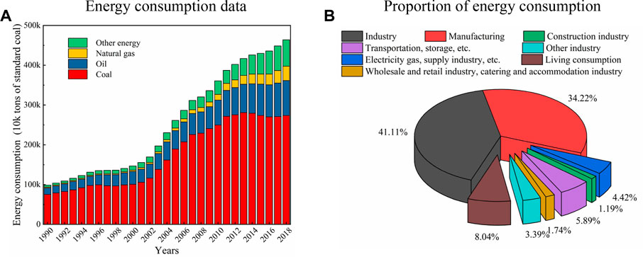
FIGURE 1. Energy consumption in different years and various fields in China. (A) Energy consumption data. (B) Proportion of energy consumption.
In order to reduce the emission of harmful gases, many scholars turn their attention to the field of high temperature heat pumps (HTHP) (Chamoun et al., 2014; Wu et al., 2016). It is hoped to use HTHP technology to replace part of the traditional calcination boiler technology to achieve 100–130°C steam production (Meggers and Leibundgut, 2011; Xing et al., 2014).
The HTHP system usually has the characteristics of high condensation temperature and the temperature lift is huge, which also makes the system has higher requirements for its circulation structure and working refrigerant. HTHP technology is divided into the compression HTHP technology and the absorption HTHP technology. Gao et al. (2021) proposed an absorbing compound HTHP with large temperature lift condition by using air source as heat source. The coefficient of performance was between 1.2 and 1.7. Liu et al. (2022) proposed to use the waste heat of low-temperature flue gas at 170°C to produce steam at 150°C, and verified by the experimental prototype that the steam heat output reached 70.15 kW. KOBELCO and CRIEPI (Japan Electric Power Company) (KOBELCO and TEPCO, 2011; Kaida et al., 2015) first proposed the use of HTHP technology for steam production, and in 2011 designed the first commercial high-temperature heat pump steam system, model SGH120. The energy efficiency coefficient (COP) of the system at 120°C was 3.5. Gong YL et al. (Liu et al., 2015) analyzed and compared five high-temperature refrigerants (R123, R141b, R245ca, R245fa and R114) based on the SGH120 model. The results show that R245fa has better comprehensive performance when the temperature lift of the system is in the range of 60–80°C, and the COP of the system is 3.65% higher than that of R114. Subsequently, Gong YL’s team (Liu et al., 2017) optimized the model of the HTHP system. By introducing the air supplement parameter (air supplement rate B) and the sub-cooler parameters (heat source water subcooling rate A), it is pointed out that the parameter-B and the parameter-A also have significant influence on the thermodynamic performance of the system. When the typical values of B and A are .4 and .2, respectively, the COP of the system is 13.5% higher than that of SGH120. Bamigbetan et al. (2018) pointed out that HTHP systems using butane as refrigerant have the ability to replace traditional boilers for steam production. To test this theoretical hypothesis, the team (Bamigbetan et al., 2019) designed a butane compressor and built an experimental platform with a HTHP system. D. H et al. (KANG et al., 2017) first analyzed the difference between SGH120 and SGH165. Summarized the influence of the flash tank and MVR device on the steam system of HTHP. In 2019, the team (Hoon et al., 2019) developed a HTHP system for steam generation, including an internal heat exchanger (IHX) based on theoretical research. The final steam produced by the system can reach temperatures of 130°C. Dai et al. (2020) adopted the structure of dual-pressure condenser to carry out piecewise heat transfer for thermal products, effectively reducing the exergic loss caused by excessive heat exchange temperature difference. Zhang YT et al. (Hao et al., 2022) conducted relevant research on the influence of IHX in the steam system of a complex HTHP, and the results showed that the COP after IHX positioning was increased by 4.87% compared with the conventional cycle. Xu et al. (2021) pointed out that the compressed heat pump had higher COP but lower exergy efficiency, indicating that exergy loss generated by the cycling process should be reduced if the compressed HTHP system was used to produce steam.
In summary, from the perspective of steam production process, the global optimization of the system is often easily neglected. The single optimization of high temperature heat pump system will easily lead to a large temperature difference between the initial temperature of thermal products and the condensing temperature of refrigerant, which will increase the exergy loss of the system. Therefore, the high temperature heat pump system is optimized globally in this paper. On the one hand, the COP and exergy efficiency of the system were improved through double flash gas injection process. On the other hand, the method of piecewise heat transfer is adopted to reduce the exergy loss caused by large heat transfer temperature difference. Finally, a set of the Dual-Flash Compound Circulation System was put forward. Based on this system, the multiple simulated annealing algorithm is used to optimize the thermodynamic parameters of the system, and a multi-objective parameter optimization algorithm for complex heat pump system is proposed, so as to improve the steam production performance of HTHP.
The research result of Zhang YT et al. (Hao et al., 2022) showed that avoiding part of refrigerant from entering the expansion valve (Ev) was an effective way to improve the exergy efficiency of heat pump system without affecting the gas-liquid ratio of FT. Meanwhile, in order to reduce the loss of exergy generated by condensation, the dual-flash compound circulation system combined multiple vapor injection process with segmental heat transfer process. The design structure of the system is shown in Figure 2:
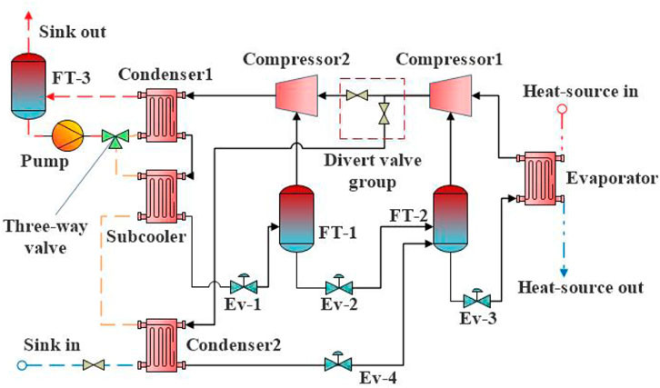
FIGURE 2. The structure of the dual-flash compound circulation system.
As shown in the figure, the dual-flash compound circulation is composed of two thermal cycles. Circulation-1 is a dual-flash vapor injection circulation consisting of two compressors and two flash tanks. The refrigerant enters into compressor-1 from the evaporator for quasi-primary compression. It is then mixed with the saturated vapor refrigerant of FT-2 and compressed again by compressor-1. This process is called the vapor injection compression process. Part of the refrigerant at the outlet of compressor-1 flows into compressor-2 through the shunt valve assembly to realize the second vapor injection compression. After this part of refrigerant completes all the compression process, it enters condenser-1 and the subcooler to transfer heat to the thermal product for steam preparation. After heat exchange, the refrigerant passes through Ev-1, Ev-2 and Ev-3 in turn, and finally enters the evaporator to form the dual-flash vapor injection circulation structure. Circulation-2 is the traditional FT quasi-two-stage compression cycle structure. The two circulation structures are coupled by sharing FT-2, Ev-3, and evaporator, and the refrigerant is shunted through the shunt valve set. Condenser-1, subcooler and condenser-2 were used to realize the segmented heat transfer process for heat products.
The pressure enthalpy characteristics of the dual-flash compound circulation system are shown in Figure 3 below:
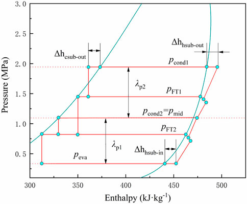
FIGURE 3. The pressure and enthalpy characteristics of the dual-flash compound circulation system.
It can be seen from the pressure enthalpy characteristics of the system in Figure 3 that there are five pressures in the HTHP system, namely condensing pressure pcond1 of the condenser-1, flash pressure pFT1 of the FT-1, condensing pressure pcond2 of the condenser-2 (Intermediate pressure pmid), flash pressure pFT2 of the FT-2 and evaporating pressure peva of the evaporator. In order to facilitate the subsequent optimization calculation, the intermediate pressure optimization experience of the traditional two-stage compression system is used, which sets the pressure pmid is set to a fixed value, denoted as Eq. 1.
The relationship between the five pressures in the system is shown in Eq. 2:
Therefore, when the pcond2 and peva in the system are determined, the intermediate pressure of the system will become a fixed value. The two flash pressures of the system will be used as variable parameters to optimize the system.
According to the dual-flash compound circulation system, the thermodynamic models of heat source, compound circulation and steam generation were established respectively.
The heat exchange of the heat source thermodynamic model is the main heat source of steam produced by the system. When the mass flow rate of the heat source is mc, Qc is used to represent the heat supply of the heat source:
where hc1 is the specific enthalpy of the heat source before heating, kJ/kg; hc2 is the specific enthalpy of the heat source after heating, kJ/kg; mc is the mass flow of the quantitative heat source, kg/s.
The HTHP compound circulation is the hub of heat transfer in the system, and its advancement determines the thermodynamic performance of the heat pump system. Meanwhile, the shunt coefficient x of the compound circulation has a significant influence on the system performance. The shunt coefficient x is the proportion of the refrigerant flow from the shunt valve to compressor-2. The mass flow rate of the refrigerant at the outlet of compressor-1 is m1, and that at the outlet of compressor-2 is m2. The relationship between m1, m2 and x can be expressed as follows:
They are assuming that the gas ratios of FT-1 and FT-2 are denoted as a and b, respectively. According to the law of mass conservation, the expressions of a and b are shown in Eq. 5.
Among them, hco-out represents the specific enthalpy of the refrigerant discharged from the sub-cooler, kJ/kg; hFT1-l, hFT1-v, hFT2-l, and hFT2-v represent the specific enthalpy of the saturated liquid refrigerant and the saturated gaseous refrigerant in the FT-1, respectively. The specific enthalpy and the specific enthalpy of the saturated liquid refrigerant and the specific enthalpy of the saturated gaseous refrigerant in the FT-2, kJ/kg; hcond2 represents the specific enthalpy of the condenser-2, in the saturated liquid state of the refrigerant, kJ/kg.
Combining Eqs 4, 5, the expression of m1 is determined from the heat supply of the heat source, which is Eq. 6.
where hcom1-in represents the specific enthalpy of the refrigerant at the inlet of the compressor-1, kJ/kg; hEv3-out represents the specific enthalpy of the refrigerant at the outlet of the Ev-3, kJ/kg.
According to the process, the heat released by Condenser-1, sub-cooler, and the Condenser-2 in the high-temperature heat pump subsystem is defined as Q1, Q2, and Q3, respectively, and expressed as:
According to the steam production process of the system, the heat released by condenser-1, subcooler and condenser-2 in the HTHP compound cycle is defined as Q1, Q2, and Q3, as shown in Eq. 7:
Among them, hcom1-out and hcom2-out represent the specific enthalpy of the refrigerant discharged from the compressor-1 and the compressor-2, kJ/kg; hcond1 represents the specific enthalpy of the refrigerant in the saturated liquid state after heat exchange in Condenser-1, kJ/kg.
The isentropic efficiency of the air-injected compressor is calculated according to the total pressure ratio of the suction and the exhaust, referring to the isentropic efficiency fitting formula that is ηis = .9343–.04478 × λp proposed by Zheng (2017), the Compressor-1 and the isentropic efficiency of Compressor-2 is expressed as:
By referring to the isentropic efficiency fitting formula of ηis = .9343–.04478 × λp proposed by Zheng (2017), the isentropic efficiency of the vapor-injected compressor is calculated according to the pressure ratio of suction and exhaust., then the isentropic efficiency of compressor-1 and compressor-2 can be expressed as:
The power consumption of compressor-1 and compressor-2 is expressed as W1 and W2:
where hcom1–1 and hcom2–1, respectively, represent the specific enthalpy of the quasi-stage compression of the refrigerant by the compressor-1 and compressor-2, kJ/kg; hcom1-in and hcom2-in represent the specific enthalpy of refrigerant at the suction port of compressor-1 and compressor-2, kJ/kg; hmix1 and hmix2, respectively represent the specific enthalpy after the vapor injection refrigerant and the quasi-stage compression refrigerant in the compressor-1 and compressor-2 are mixed, kJ/kg.
The COP of the dual-flash compound circulation system can be expressed as Equation 10.
It is assumed that the initial temperature of the inlet hot water at the steam generating side is Tsink0, and the heat loss in the heat transfer process is ignored. The mass flow rate of the hot water at the steam generating side is msink, which is the steam output obtained by the system, as shown in Equation 11.
hsink is the specific enthalpy of the final saturated steam, kJ/kg; hsink0 is the inlet hot water at the steam generating side, kJ/kg.
When the ambient temperature is TAmb, the specific enthalpy and specific entropy of the corresponding environment are expressed as hAmb and sAmb. According to the definition of exergy, exergy loss expressions of the dual-flash compound circulation system equipment in each process are shown in Table 1 below:
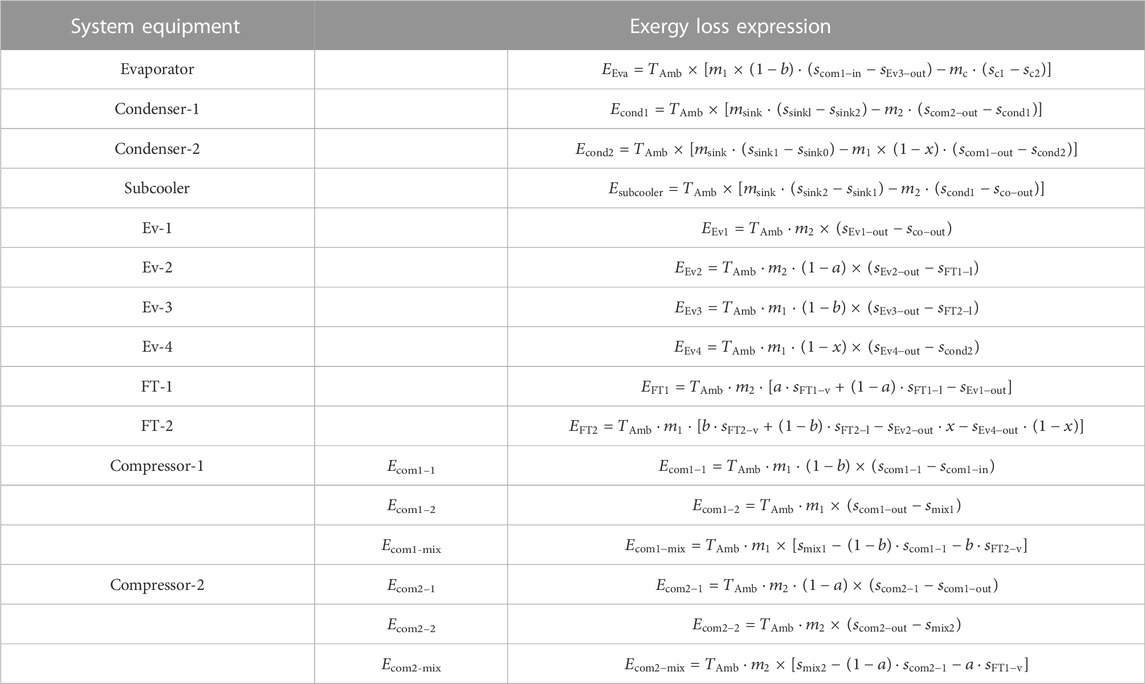
TABLE 1. Exergy loss model of each component.
Through the expression of exergy loss of equipment in each process of the system, the total exergy loss of the system can be obtained, which is expressed as Eq. 12.
The exergy efficiency of the system is the ratio of exergy output and exergy obtained by the system, which can reflect the advancement of a circulatory system to a large extent, and can be expressed by Eq. 13.
Exergy loss of the system could be reduced and thermodynamic performance of the system could be improved in the hierarchical heat transfer process, but it had certain restrictions on the heat transfer relationship of the system. When the initial temperature of the supplementary hot water is Tsink0, and the mass flow rate is msink, assuming that the pinch temperature in the heat transfer process is 5 °C, according to the second law of thermodynamics, the water temperature reached after the absorption of Q3 should not be higher than Tcond2 –5°C. Set this limit temperature as Tsink’ = Tcond2 –5°C, then the specific enthalpy of the hot water added at this temperature is hsink’. When the hot water absorbs Q2 and Q1, the final production steam temperature should not be higher than Tcond1 –5, denoted as Tsink. The hsinkv is the specific enthalpy of saturated steam and hsinkl is the specific enthalpy of saturated hot water. Due to the conservation of energy and mass during the cycle operation of the system, two heat specific requirements related to the phase transition of hot water were derived, denoted Rcondition1 and Rcondition2 respectively. The relevant expression is as follows (14).
Based on this, when the system satisfies Eq. 15 at the same time, the long-term steady operation of the system can be realized.
It is assumed that the evaporation temperature of the system is 50°C, the evaporation superheat is 5°C, the condensation temperature is 120°C, and the condensation supercooling degree is 5°C. When the mass flow rate of heat source is 1 kg/s, and the initial temperature is 60°C. The above parameters were quantified, the shunt coefficient x and pFT1 and pFT2 were set as variable parameters, and the calculation system was optimized to maximize COP.
The relationship between Rcondition1, Rcondition2, and Q1, Q2, and Q3 are shown in Figure 4.
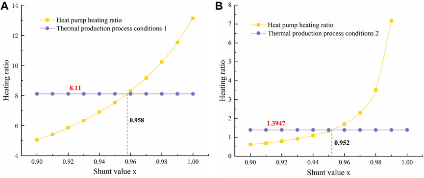
FIGURE 4. The influence of the shunt coefficient x on the process limitation under certain parameters. (A) Rcondition1 relationship. (B) Rcondition2 relationship.
It can be seen that, with the change of x in the dual-flash compound circulation system, the heat transfer ratio of Rcondition1 was constant 8.11, while Rcondition2 was always equal to 1.3947. It follows that when the evaporation temperature is set, the value of Rcondition1 depends only on the maximum condensing temperature of the system, while Rcondition2 is not only affected by the Tcond1, but also related to the Tcond2 of the system. Combined Rcondition1 and Rcondition2, the shunt coefficient x needs to be greater than .958 and .952 at the same time. Therefore, the shunt coefficient x greater than .958 under this condition is the technical condition limitation of the system.
Due to the complex cycle process of the system, the parameters in the system have coupling and variability. Therefore, it is necessary to optimize each parameter in the system by appropriate optimization algorithm to ensure the heating performance of the system. The multivariable simulated annealing algorithm has the advantages of simple optimization process and strong robustness, which is suitable for the multi-objective parameter optimization process of the Dual-Flash Compound Circulation system (Kryukova et al., 2019; Zhang et al., 2022).
Simulated annealing algorithm (SA) is an optimization algorithm which is often used to find the global nadir through the simulated annealing process. For the parameter optimization of the high point bit, the optimization process can be realized by adding symbols or changing the operation direction. The schematic diagram of the algorithm is shown in Figure 5 (Bai and Liu, 2016).
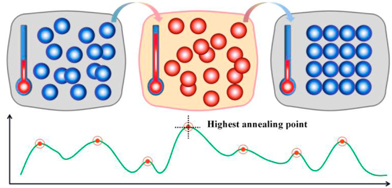
FIGURE 5. Principle of the simulated annealing algorithm.
It can be seen from the annealing calculation that there are multiple annealing points during the whole annealing process. Under the action of multiple influential variables, the highest annealing point of the whole process is finally obtained as the unique solution of the system optimization. In order to maintain the stability of the system, some unnecessary variables need to be reduced. Thermodynamic model based on the system, the shunt coefficient of x, system too cold quantity ΔTsub-co, the FT-1 flash pressure pFT, FT-1 flash pFT COP of the system have a significant impact, including x and ΔTsub-co has also changed the constraints in the process of system. Therefore, the above four parameters as variables, determine multivariate calculation process of simulated annealing algorithm, as shown in Figure 6.
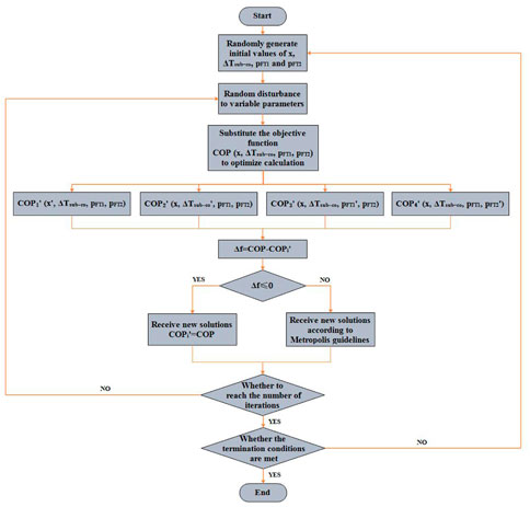
FIGURE 6. System multivariate simulated annealing optimization algorithm flow.
Due to the system variables is more, the algorithm parameters must be large enough to satisfy the movement step length, step length is set to 100,000. Simulated annealing temperature gradient reduction should be small enough, the period is set to .130. The thermodynamic model of the system was introduced into the algorithm flow, as shown in Figure 6, and the maximum COP was taken as the optimization condition of the judicial system. When the judgment condition and termination condition are satisfied at the same time, the system optimization parameters obtained are substituted into the system thermodynamic model to obtain the system conditions and other thermodynamic parameters.
The working condition of the system is formulated. The evaporation temperature is 50°C, the condensation temperature tends to change within the range of 110–140°C, the pinch temperature of heat transfer in the system is 5°C, and the intermediate pressure is calculated through Eq. 1 to reduce the calculation time of the optimization model. The other intermediate parameters were optimized according to the multivariate simulated annealing algorithm. As the condensation temperature of the system changes, the relationship between the intermediate pressure corresponding to the maximum COP of the system is shown in Figure 7 below.
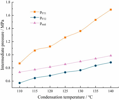
FIGURE 7. Variable relationship of intermediate pressure at different condensation temperatures.
The pmid is a variable related to the condensing pressure and evaporation pressure. According to Eq. 1, when the evaporation pressure does not change, pmid shows a linear change with a slow increase as the condensation temperature increases. The flash pressure pFT1 and the pFT2 fluctuated with the increase of the condensation temperature. This is due to the parameter fluctuation caused by considering the global optimal solution in the multi-objective optimization process of the system. From the fluctuation range, with the increase of condensation temperature, the change of pressure variables in the system is more significant. However, the variation range of the other two variables parameters is relatively small, and the variation trend is shown in Table 2.
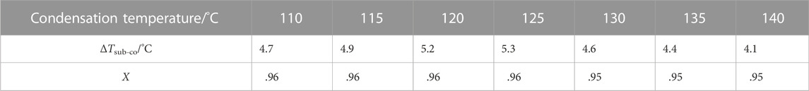
TABLE 2. x and ΔTsub-co change trend with condensation temperature.
From the optimized parameters, it can be concluded that the split coefficient x is in the limit position as the condensation temperature changes. Therefore can be concluded that under the conditions, the smaller x leads to the higher the COP of the system. When the condensing temperature was higher than 125°C, the minimum value of the shunt coefficient x was reduced from .96 to .95, which verified that Rcondition1 and Rcondition2 were affected by the condensing temperature and gradually decreased with the increase of the condensing temperature. At the same time, the optimal subcooling degree of the system increases first and then decreases with the increase of the condensation temperature, and the cut-off point is the same as the condensation temperature of 125°C. Therefore, the optimal value of the subcooling degree has a certain correlation with the condensation temperature Tcond1 and the shunt coefficient x. To analyze the influence of x on the subcooling degree, the working condition in Table 2 is defined as working condition-1, and the x is set as working condition-2. In this case, the variation of the parameters of the subcooling degree corresponding to the optimal COP of the system is shown in Figure 8.
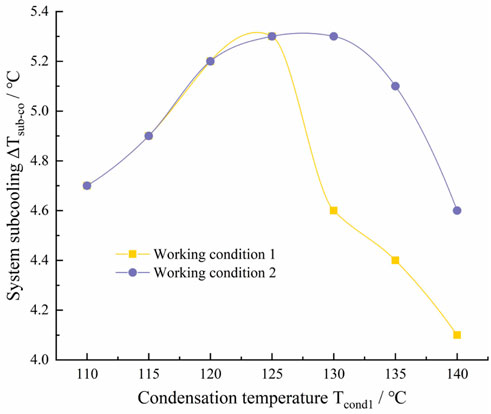
FIGURE 8. System subcooling changes under two working conditions.
Figure 8 shows that the system subcooling under the two working conditions shows a trend of first increasing and then decreasing. However, the difference is that the variation of the value in working condition-1 is relatively smooth, while the value in working condition-2 drops abruptly when the condensation temperature is higher than 125°C. The reason for this trend is that the temperature lift of the system causes a change in the intermediate pressure, which indirectly changes the Rcondition2 required by the process through the condensing temperature Tcond2. When the final condensation temperature Tcond1 of the system is higher than 125°C, The SA algorithm will reduce the subcooling to meet the requirements of Rcondition2.
The dual-flash compound circulation system is mainly used to convert hot water into steam. In addition to the COP of the system, the steam production and cooling capacity of the unit refrigerant will also be used as the standard parameters to evaluate the thermodynamic performance of the system.
To simplify the calculation, the influence of system refrigerant flow rate on the dual-flash compound circulation system was analyzed under the specified cooling capacity, and the mass flow relationship of refrigerant in each stage of compound circulation was analyzed is show in Figure 9.
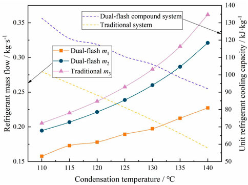
FIGURE 9. Refrigerant changes with condensing temperature under rated cooling capacity.
When the cooling capacity and evaporation temperature are constant, the mass flow of refrigerant through the evaporator in the dual-flash compound circulation system and the traditional two-stage compression system are both m1, and the mass flow of refrigerant discharged from the high-pressure compressor are m2 and m3, respectively. As shown in Figure 8, with the same cooling capacity, m2 increases from .195 kg/s to 0.321 kg/s, and m3 increases from .205 kg/s to .362 kg/s with the increase of condensation temperature Tcond1. The m3 is 5.13%–12.8% higher than m2. Under the same cooling capacity, the increase in refrigerant demand leads to an increase in cost, and the circulation process may cause a greater resistance loss. In addition, according to the mass flow relationship of refrigerant, under the action of equivalent circulating refrigerant, the unit refrigerant refrigerating capacity of the traditional two-stage compression system and the dual-flash compound circulation system showed a downward trend with the increase of the condensation temperature. However, the unit refrigerating capacity of the dual-flash compound circulation system is 21.42%–37.17% higher than that of the traditional two-stage compression system. Therefore, facing the same production scale, the dual-flash compound circulation system can more fully use of the heat source of heat.
The thermodynamic models of the traditional two-stage compression system and the dual-flash compound circulation system were calculated. Under the same environment, the maximum COP of the two systems at different condensing temperatures could be obtained through parameter optimization by SA algorithm, as shown in Figure 10.
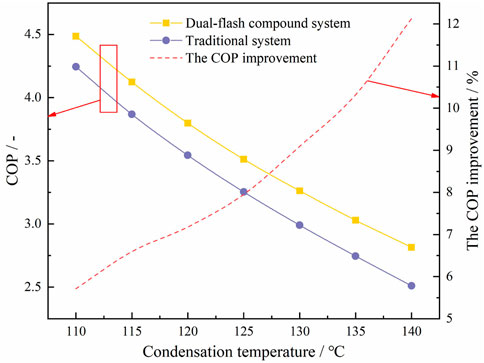
FIGURE 10. System COP changes at different condensation temperatures.
As shown in Figure 10, with the increase of the condensation temperature, the maximum COP of both the traditional two-stage compression system and the dual-flash compound circulation system showed a downward trend. Among them, the COP of the dual-flash compound circulation system decreased from 4.49 to 2.81, which was 5.71% ∼ 12.13% higher than that of the traditional two-stage compression system in the same environment. This trend shows that the higher the condensation temperature required by the system, the more advantages the dual-flash compound circulation system has in heating.
To verify this advantage, the vapor production per unit refrigerant was compared between the two systems under different condensing temperature requirements, as shown in Figure 11.
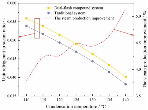
FIGURE 11. The change of unit steam volume of the system at different condensing temperatures.
Figure 11 shows the variation of steam production for the two systems with the same mass flow rate of refrigerant. When the condensing temperature of the system was within the range of 110–140°C, the mass flow rate of steam generated by the dual-flash compound circulation system was .0401–.0559 kg/s. Compared with the conventional two-stage compression system, the steam production is increased by 3.79%–5.14%. In addition, in the process of steam production, there are two fluctuation points when the system condensing temperature is 120°C and 130°C. This phenomenon is exact because the two fluctuation points of m1 in Figure 10 correspond to the change of the system steam production caused by the change of m1, which does not affect the optimization theory.
In the thermodynamic analysis of heat pump system, the COP can usually reflect the heating performance of the system at the economic benefits, but it cannot reflect the advanced nature of the thermal cycle of the system. The advancement of thermodynamic cycle of a system is usually expressed by thermodynamic perfection or exergy efficiency. Therefore, exergy model of the dual-flash compound circulation system was established, exergy changes of each component in the compound circulation of the system were analyzed, and the pros and cons of the system were further judged. As the change of condensation temperature, describes the exergy loss of each component in the system as shown in Figure 12.
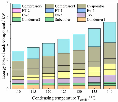
FIGURE 12. The exergy loss of each component of the system with the condensing temperature under the same heating capacity.
Under the condition of the large temperature lift, the total exergy loss of the system increases from 2.646kW to 4.649 kW with the increase of condensing temperature, and the exergy loss of the compressor accounts for 50.12%–54.35%. It can be concluded that the compressor is the main component causing exergy loss in the system under the condition of high condensing temperature and the large temperature lift. As the condensing temperature increased in the system, the percentage of exergy loss of compressor fluctuated slightly, while the percentage of exergy loss of condensers -1, evaporator, Ev-2 and Ev-3 changed significantly.
When the condensing temperature of the system increased from 110°C to 140°C, the proportion of exergy loss of condenser-1 increased from 9.98% to 17.16%, and that of evaporator from 4.83% to 8.22%. The exergy loss of Ev-2 decreased from 4.23% to 4.11%, the Ev-3 decreased from 8.49% to 8.33%. The result showed that under the same heating capacity, with the increase of temperature Tcond1, the exergy loss generation process of the system gradually changed from pressure transformation process to heat transfer process. It is worth noting that the exergy loss ratio of Ev-1 did not fluctuate. Therefore, it can be concluded that the main reason for the change of exergy loss of Ev-2 and Ev-3 is the vapor injection process. In order to further understand the advancement of thermal cycle of the system, exergy efficiency of the system was calculated and compared with that of traditional two-stage compression cycle.
According to the exergy model of the system, the variation trend of exergy efficiency of the system at different condensing temperatures is obtained, as shown in Figure 13.
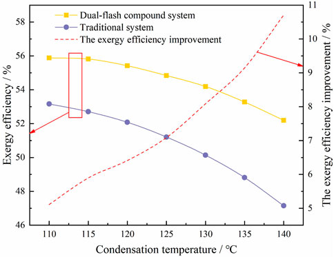
FIGURE 13. The trend of exergy efficiency of the system under the same cooling capacity.
As can be seen, when the condensing temperature increased from 110°C to 140°C, the exergy efficiency of the dual-flash compound circulation system decreased from .5588 to .522. On the one hand, the overall exergy loss of the system increases with the increase of condensing temperature. On the other hand, the increase of pressure ratio increases the compression power of the compressor. However, the exergy efficiency of the traditional two-stage compression system decreased from .5316 to .4715 in the same environment, which was 5.11%–10.71% lower than that of the dual-flash compound circulation system. Thus, from the perspective of the advanced nature of thermal cycle, the dual-flash compound circulation system has obvious advantages.
To verify the feasibility of the theoretical model, the system can be modeled and simulated by using Aspen Plus V9 software. Due to the large number of parameter variables and constraints in the theoretical model, in order to simplify the calculation process, the heat transfer iteration process of the simulation model is replaced by energy value through the relationship between the output heat in Rcondition1 and Rcondition2, and the system model is shown in Figure 14 below.
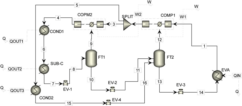
FIGURE 14. Simulation verification model.
The simulation environment of the simulation system takes the evaporation temperature of 50 °C and the condensation temperature of 120 °C as an example. The physical property data of REFPROP are substituted into Aspen Plus, and QOUT1, QOUT2 and QOUT3 are set as the cold utilities. The boundary conditions are set respectively according to the theoretical calculation values. The pressure of thermal products is set as a fixed value of .169 MPa (saturated steam 115°C), and the inlet temperature of QOUT3 is 50°C. The outlet vapor fraction of QOUT1 is 1. QIN is the hot utilities, and the initial value of heat refers to the theoretical calculation of heat supply from the heat source.
The technical parameters of the compressor and expansion valve in circulation are shown in the following Table 3 and Table 4.

TABLE 3. Technical parameters of the expansion valve to be used.
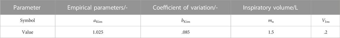
TABLE 4. Technical parameters of the proposed compressor.
The resistance loss along the pipeline is not considered. The theoretical optimized system parameters were used as the initial values of each pressure in the simulation model, where pcond1 = 1.9275 MPa, pFT1 = 1.126 MPa, pmid = .8145 MPa, pFT2 = .6828 MPa, peva = .3442 MPa. The compressor is selected as a compressor module with double trays and vapor injection performance. In order to compare with the theoretical value, the isentropic efficiency of compressor-1 and compressor-2 is based on the theoretical value, which is .757, .831, .813 and .782, respectively. In the simulation model, the splitter is used to replace the shunt valve group, and the shunt coefficient x is set to .96. The initial refrigerant mass flow rate at node 6 in Figure 7 was set to .2236 kg/s. After setting the initial conditions, the parameters of the variable pressure element (compressor, expansion valve) in the simulation model will be debugted until steady state. The state of each node is shown in Figure 15 below.
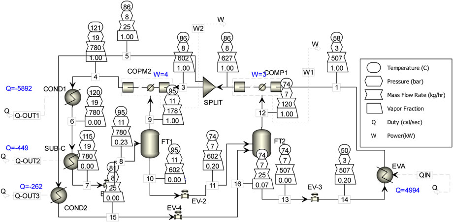
FIGURE 15. The state of each node of the model after the steady-state.
It can be seen from Figure 15 that under the cold utilities and the hot utilities and restrictions, the simulation system has no errors and warnings, indicating that the theoretical model is indeed feasible. According to the numerical relationship between the heating energy and compressor power consumption, the COP of the simulation system is 3.716, which is only 2.16% different from the theoretical calculation value. These errors are due to the system performance deviation caused by the inability to control the precise circulating refrigerant in the simulation system, and do not affect the feasibility and performance analysis of the system.
The dual-flash compound circulation system was used to realize the efficient heating process of hot water to steam. The system reduced the heat loss of key components such as compressor and expansion valve during heating process, and had better thermodynamic performance under the same working condition.
(1) The thermodynamic model of double flash compound cycle system is established, and the limiting conditions of the thermodynamic model are also established. When the temperature lift from 50°C to 120°C, the shunt coefficient in the system should not be less than .958.
(2) Combined with simulated annealing algorithm, a multi-objective parameter optimization model with COP as the optimization objective was established. Through optimization calculation, it is found that the pressure of FT-1 and FT-2 increases almost linearly with the increase of Tcond1. However, the shunt coefficient x and the system undercooling degree largely depend on the technological conditions of the system, especially the system undercooling degree.
(3) According to theoretical calculation, the COP of the dual-flash compound circulation system was in the range of 2.81–4.49 when the condensation temperature was in the range of 110–140°C, which was 5.71%–12.13% higher than that of the traditional two-stage compression system. The exergy efficiency of the system was 5.11%–10.71% higher than that of the dual-flash compound circulation system. The comprehensive analysis showed that the dual-flash compound circulation system had more advantages when facing the heating condition with high condensation temperature.
(4) In addition, Aspen was used to simulate the dual-flash compound circulation system. The results showed that the COP calculated by the simulation results was only 2.16% different from the theoretical value after the system was in steady state, which proved that the system had certain feasibility.
The raw data supporting the conclusion of this article will be made available by the authors, without undue reservation.
ZH conceived and wrote the paper; ZY was responsible for scheme establishment and detail optimization; WL conducted model inspection and logical sorting; XJ provided funds and established the direction; HZ for data programming; ZG carried out image optimization; ZY does grammar check.
This study was financially supported by the National Natural Science Foundation of China (Grant Nos. 51876055, 51806060, and U1504524) and the Natural Science Foundation of Henan Province (Grant Nos. 182300410233) and the Shanghai Heimdallr Energy Saving Technology Co., Ltd. (05N14030820).
Author XJ was employed by the company Shanghai Heimdallr Energy Saving Technology Co., Ltd.
The remaining authors declare that the research was conducted in the absence of any commercial or financial relationships that could be construed as a potential conflict of interest.
All claims expressed in this article are solely those of the authors and do not necessarily represent those of their affiliated organizations, or those of the publisher, the editors and the reviewers. Any product that may be evaluated in this article, or claim that may be made by its manufacturer, is not guaranteed or endorsed by the publisher.
Bai, X., and Liu, Y. (2016). Reliability analysis on civil engineering project based on integrated adaptive simulation annealing and gray correlation method. Front. Struct. Civ. Eng. 10 (4), 462–471. doi:10.1007/s11709-016-0361-y
Bamigbetan, O., Eikevik, T. M., Neks, P., Bantle, M., Schlemminger, C., Dallai, M., et al. (2018). “Experimental investigation of a hydrocarbon piston compressor for high temperature heat pumps,” in 24th International Compressor Engineering Conference.
Bamigbetan, O., Eikevik, T. M., Neksa, P., Bantle, M., and Schlemminger, C. (2019). Experimental investigation of a prototype R-600 compressor for high temperature heat pump. Energy (Oxford, U. K.) 169 (15), 730–738. doi:10.1016/j.energy.2018.12.020
Cao, X.-Q., Yang, W.-W., Zhou, F., and He, Y.-L. (2014). Performance analysis of different high-temperature heat pump systems for low-grade waste heat recovery. Appl. Therm. Eng.
Chamoun, M., Rulliere, R., Haberschill, P., and Peureux, J. L. (2014). Experimental and numerical investigations of a new high temperature heat pump for industrial heat recovery using water as refrigerant. Int. J. Refrig. 44, 177–188.
Dai, Baomin, Liu, Xiao, Liu, Shengchun, Wang, D., Meng, C., Wang, Q., et al. (2020). Life cycle performance evaluation of cascade-heating high temperature heat pump system for waste heat utilization: Energy consumption, emissions and financial analyses. Energy 261, 125314. doi:10.1016/j.energy.2022.125314
Gao, J. T., Xu, Z. Y., and Wang, R. Z. (2021). An air-source hybrid absorption-compression heat pump with large temperature lift. Appl. Energy, 291.
Hao, Z., Yanting, Z., Jingyu, X., Lin, W., and Zheng, H. (2022). Performance analysis of IHX-based quasi-two-stage vapor compression heat pump system for high-temperature steam production. ENERGY Technol. 8, 200063.
Hoon, K. D., Sun-Ik, N., Woo, Y. J., Lee, J. H., and Kim, M. S. (2019). Experimental study on the performance of a steam generation heat pump with the internal heat exchanging effect. Int. J. Refrig. 108, 154–162. doi:10.1016/j.ijrefrig.2019.09.003
Kaida, T., Sakuraba, I., Hashimoto, K., and Hasegawa, H. (2015). Experimental performance evaluation of heat pump-based steam supply system. IOP Conf. Ser. Mat. Sci. Eng. 90 (1), 012076. doi:10.1088/1757-899x/90/1/012076
Kang, D., Sun-Ik, N., Kim, M. S., et al. (2017). Recent researches on steam generation heat pump system. Int. J. Air-Cond. Ref. 25 (4), 1730005–1730008. doi:10.1142/s2010132517300051
Kryukova, A. E., Konarev, P. V., Volkov, V. V., and Asadchikov, V. (2019). Restoring silicasol structural parameters using gradient and simulation annealing optimization schemes from small-angle X-ray scattering data. J. Mol. Liq. 283, 221–224. doi:10.1016/j.molliq.2019.03.070
Liu, B., Gong, Y., Lu, Z, and Yao, Y (2015). Several working fluids for high temperature heat pump steam system. Kezaisheng Nengyuan 33 (12), 1755–1761.
Liu, B., Gong, Y., Lu, Z., Qu, Z., and Gao, Y. (2017). Performance analysis and optimization of a coupling sub-cooler heat pump steam system in a quasi two-stage compression cycle. Huagong Jinzhan 36 (07), 2360–2367.
Liu, C. C., Han, Wei, and Xue, X. D. (2022). Experimental investigation of a high-temperature heat pump for industrial steam production. Appl. Energy, 312.
Meggers, F., and Leibundgut, H. (2011). The potential of wastewater heat and exergy: Decentralized high-temperature recovery with a heat pump. Energy Build. 43 (4), 879–886. doi:10.1016/j.enbuild.2010.12.008
Wu, Xiaokun, Xing, Ziwen, He, Zhilong, Wang, X., and Chen, W. (2016). Performance evaluation of a capacity-regulated high temperature heat pump for waste heat recovery in dyeing industry. Appl. Therm. Eng. 93 (C), 1193–1201. doi:10.1016/j.applthermaleng.2015.10.075
Xu, Z. Y., Gao, J. T., Hu, Bin, and Wang, R. (2021). Multi-criterion comparison of compression and absorption heat pumps for ultra-low grade waste heat recovery. Energy 238, 121804. doi:10.1016/j.energy.2021.121804
Zhang, Y. T., Zhang, Hao, Wang, Lin, Jingyu, X., Lumeng, H., Jingkai, C., et al. (2022). Application and analysis of multi-stage flash vaporization process in steam production in high-temperature heat pump system with large temperature difference. Int. J. Refrig. 133, 123–132. doi:10.1016/j.ijrefrig.2021.09.035
Zheng, Nan (2017). Research on novel two-stage heat pump with vapor expander and its key thermal process using zeotropic mixtures Tianjin University
COP Coefficient of performance (-)
h Enthalpy (kJ/kg)
s Entropy (kJ/(K·kg))
m Mass flow rate (kg/s)
T Temperature (K)
p pressure(MPa)
E Exergy (kW)
Q Heat transfer (kW)
W Power consumption (kW)
η Efficiency (-)
a, b Vapor ratio (-)
TAmb Ambient temperature (K)
x The split coefficient (-)
Cond Condensation
Eva Evaporation
Ev Expansion valve
Comp Compressor
FT Flash tank
sub-co Subcooler
sink Thermal product
c Heat source
in Intake
out Exhaust
mid Middle-pressure position
is Isentropic state
HTHP High-temperature heat pump
IHX Internal heat exchanger
SA Simulated annealing algorithm
m1 Compressor-1 refrigerant displacement
m2 Compressor-2 refrigerant displacement
Rcondition1 Cyclic requirement condition one
Rcondition2 Cyclic requirement condition two
Q1 Heat transfer of the Condenser-1
Q2 Heat transfer of the Subcooler
Q3 Heat transfer of the Condenser-2
cond1 Condenser-1
cond2 Condenser-2
aKim, bKim, mn, VIns SA algorithm parameters
Keywords: high-temperature heat pump steam-system, multiple annealing optimization, energy analysis, the dual-flash compound circulation system, large temperature lift conditions
Citation: Hao Z, Yanting Z, Lin W, Jingyu X, Zheng H, Guangzhi Z and Yunlong Z (2023) System optimization of steam generation in the dual-flash compound circulation system. Front. Energy Res. 10:1043087. doi: 10.3389/fenrg.2022.1043087
Received: 13 September 2022; Accepted: 29 November 2022;
Published: 04 January 2023.
Edited by:
Yongming Han, Beijing University of Chemical Technology, ChinaReviewed by:
Jiangping Chen, Shanghai Jiao Tong University, ChinaCopyright © 2023 Hao, Yanting, Lin, Jingyu, Zheng, Guangzhi and Yunlong. This is an open-access article distributed under the terms of the Creative Commons Attribution License (CC BY). The use, distribution or reproduction in other forums is permitted, provided the original author(s) and the copyright owner(s) are credited and that the original publication in this journal is cited, in accordance with accepted academic practice. No use, distribution or reproduction is permitted which does not comply with these terms.
*Correspondence: Zhang Yanting, eXR6aGFuZ0B1cGMuZWR1LmNu; Wang Lin, d2xoYXVzdEAxNjMuY29t
Disclaimer: All claims expressed in this article are solely those of the authors and do not necessarily represent those of their affiliated organizations, or those of the publisher, the editors and the reviewers. Any product that may be evaluated in this article or claim that may be made by its manufacturer is not guaranteed or endorsed by the publisher.
Research integrity at Frontiers
Learn more about the work of our research integrity team to safeguard the quality of each article we publish.