- 1State Grid Hubei Electric Power Company Electric Power Research Institute, Wuhan, China
- 2College of Automation &College of Artificial Intelligence, Nanjing University of Posts and Telecommunications, Nanjing, China
Photovoltaic (PV) grid-connected will reduce the inertia of the system, which has an effect on power system frequency reliability. In order to clarify the frequency stability situation of power system when photovoltaic participates in frequency regulation, this paper first establishes the load frequency control (LFC) model of the power system with photovoltaic based on the analysis of the traditional LFC model of the power system. Secondly, based on the Pade approximation method, the communication delay in the control loop is linearized. The frequency stability of power system with photovoltaic participation in frequency regulation is characterized by system frequency steady-state error, feedback system sensitivity, and closed-loop system stability margin. According to the index calculation and theoretical derivation, the influence of system frequency regulation related parameters on frequency characteristics is analyzed. Finally, on the matlab/simulink simulation environment, the frequency stability methodological approach presented in this research is validated. The results of the simulations demonstrate the effectiveness of this analytical approach in assessing the frequency stability of a power system with photovoltaic frequency regulation while taking communication latency into account. It can provide guidance for the power grid’s secure operation and control when photovoltaics participate in frequency regulation.
Introduction
In recent years, with the low-carbon transformation of energy structure, the access of a high proportion of new energy and power electronic equipment has become a significant feature of modern power system (Jain et al., 2020). The development of the power system has benefited greatly from the widespread use of photovoltaic power generation, one of the most prominent new energy generation technologies (Gao et al., 2022). As a large number of grid-connected inverters need to be installed for photovoltaic grid-connected operation (Fu et al., 2022), the frequency band that the power system needs to consider and control continues to expand (Jiang et al., 2018). Moreover, after photovoltaic grid-connected, their number continued to increase, requiring high-speed coordinated control to ensure the efficient operation of the grid. With the quantitative change of an increasing proportion of photovoltaic grid-connected, the power system presents the development trend of power electronization (Tafti et al., 2021).
However, photovoltaic is connected to the power grid through a large number of power electronic devices, and it does not have the ability of primary frequency regulation, so it cannot actively respond to the frequency response of the system (Cuello-Polo and O’Neill-Carrillo, 2021). The incorporation of power electronic interface makes the frequency regulation characteristics of each node significantly heterogeneous in the frequency dynamic process, which worsens the frequency response characteristics. Power systems with photovoltaics are subject to many factors such as light intensity and temperature, which produce random fluctuations in output power (Medina-Quesada ÁGil-González et al., 2022) and deviations in system frequency (Al-Shetwi et al., 2022). If the frequency regulation capacity is insufficient, it is very easy to trigger the low-frequency load shedding protection action (Quan et al., 2019), which would lead the system to disconnect in severe circumstances, compromising the power grid’s safety. On the other hand, the dependable functioning of a photovoltaic power grid requires corresponding control system to monitor, control and dispatch (Sultan et al., 2019) it in real time. Effective communication and information technology can improve the quality, efficiency and security of energy transmission. An affect of the communication network on the safe and steady functioning of the power system should always be recognized (Saxena and Shankar, 2022). Any existence of latency will impact the system’s performance characteristics and diminish overall convergence speed. It is especially harmful to the power system’s frequency stability (Phan-Tan and Hill, 2021).
In view of the unsafe and stable analysis of power grid frequency, the key to effectively evaluate and analyze the frequency situation of power system is to establish a load frequency control model with photovoltaic frequency regulation (Bakeer et al., 2022). The analysis methods of power system frequency response characteristics (You et al., 2018) mainly include full time domain simulation model, artificial intelligence frequency response estimation model and system load frequency control model. Based on the detailed models of power system components, full time domain simulation solves the differential equations to obtain the frequency response information of the system after disturbance, which has high accuracy. However, it is difficult to apply in real time due to the large amount of calculation and time field calculation (Prakash et al., 2018). The frequency response calculation based on artificial intelligence algorithm has better prediction accuracy and speed (Zhang et al., 2020). However, since this physical meaning of the concept is ambiguous, providing suggestions for actual system parameter optimization is challenging. System load frequency control model has the advantages of low order, analyzability and fast operation, and is commonly utilized in power grid frequency stability analysis (Li and Zhang, 2021). However, the traditional LFC model only considers thermal power units and ignores the influence of frequency regulation dead zone. It is not suitable for high proportion PV access scenarios, and directly causes errors between simulation analysis and actual measurement results (ChunYi et al., 2019; Adetokun et al., 2020). On this basis, scholars including both home and abroad have conducted extensive studies on the frequency characteristics of power system for different frequency regulation strategies.
At present, photovoltaic grid-connected provides a flexible control means for power system frequency regulation. However, the research on the frequency situation of power system considering photovoltaic participation in frequency regulation is still relatively scarce. Therefore, under the trend of diversification of frequency regulation resources in power system, how to analyze the frequency characteristics of power system in which PV participates in frequency regulation has become a research hotspot. Yan et al. (2019) builds photovoltaic system model and simulation based on shading effect, and evaluates the voltage and transient stability effect of photovoltaic system through experimental research. It reflects the transient response characteristics of photovoltaic power generation model. Li et al. (2021) performed a comparison analysis of how photovoltaics affected system reliability at diverse penetrations. Included are three distinct situations as well as their associated models-units and centralized units with and without the capacity to adjust voltage. Using such models and actual power grid data, the influence is analyzed through eigenvalues, voltage stability and transient stability. Rezaei J and his research team in (Rezaei et al., 2022) investigated the influence of exceptionally large solar energy generation on the dynamic characteristics of power grids, including rotation speed and reliability requirements. Therefore, a detailed equivalent dynamic model and corresponding controller are established. A comprehensive re-placement scenario is also proposed, including different photovoltaic penetrating, installation, and voltage control schemes. The frequency reliability and rotor speed stability are explored and assessed through modes and frequency response. In (Nanou et al., 2015), the authors present different grid-connected photovoltaic model featuring adjustable load current regulation and power control ability that seems to be appropriate for electric grid investigation. A power distribution method is demonstrated. The scheme can operate at a predetermined power reserve level and allows the droop type and inertia response to be provided by modulating the voltage of a photovoltaic module. In addition, a linearized small signal model was constructed to assess the effect of photovoltaic resources and equipment upon that stability of the power generation regulator while the device is performing inside a finite state machine. The simulation results demonstrate that the recommended control method can successfully modify pv output power to achieve frequency responses even when environmental and operational circumstances fluctuate dramatically.
However, for the LFC model with photovoltaic, the above literature focuses on the frequency regulation control strategy. Among them, there is a lack of quantitative description indicators for the free frequency response characteristics of the power system, which is difficult to guide the optimal configuration of the system control when the photovoltaic modules are connected to the public grid in theory. Nor can we theoretically describe the effect of photovoltaic frequency regulation upon power system frequency response qualities. How to effectively evaluate the frequency stability of the system with photovoltaic frequency regulation needs further research. Wu et al. (2020) investigate the transient system reliability of a grid-connected photoelectric producing power system. Taking the maximum frequency deviation as the index, the range of the maximum photovoltaic capacity of the system is determined, and the influence of high permeability photovoltaic high disturbance system on frequency stability is studied. Based upon surface matching, a strategy for evaluating and predicting the frequency dynamic properties of PV devices and techniques is given. The essential requirements of extremely high photovoltaic accesses are supplied at various nodes. The modification of the frequency shift properties of high capacity units is presented as such an improvement measure. Schinke and Erlich (2018) quantitatively evaluated the impact of the high permeability of small photovoltaic units embedded on the frequency and voltage security of massive interconnections in the distribution grid. Based on the fully integrated model of photovoltaic power station, the influence of various requirements of voltage control, frequency control and active power control in emergency is analyzed. Simulations on representative benchmark networks are used to evaluate and quantify the overall impact. Appropriate methods are suggested to enhance the voltage/frequency stability of the system. However, although the above literature analyzes the influence of control parameters, it does not take into account the impact of communication delay in the actual power grid operation. The evaluation and analysis of the frequency stability of the power system where PV participates in frequency regulation is weak. This is not conducive to the current power grid frequency situation prediction.
Large scale photovoltaic power system with randomness and uncertainty impacts the system balance, and then affects the frequency characteristics of the system. At the same time, the existence of communication delay also threatens the system frequency security to a certain extent. Therefore, it is very important to analyze the frequency stability characteristics of the power system with photovoltaic frequency modulation taking into account the communication delay and clarify the system frequency situation. In this paper, based on the traditional power system load frequency control model, the frequency response model of the power system with photovoltaic is constructed considering the frequency modulation of photovoltaic participating system and the influence of communication delay. The delay is linearized by Pade approximation. The frequency stability of power system under photovoltaic participation in frequency modulation is analyzed and evaluated by establishing three indicators: system frequency steady-state error, feedback system sensitivity, and closed-loop system stability margin.
Using Pade approximation to deal with time delay can significantly reduce the complexity of modeling and the total cost of computing time, and can provide better services for the study of power system frequency characteristics. The proposed frequency stability margin index provides a new idea for the stability of photovoltaic participating system frequency modulation, and improves the accuracy and effectiveness of quantitative assessment of photovoltaic grid connected system frequency stability. It can provide operators with a more intuitive measurement that represents the current frequency stable operation state of the power system, and conveniently take into account the impact of communication delay on the frequency modulation of photovoltaic participating systems. It is helpful for power control personnel to grasp the frequency stability of power system more accurately. This will have a high theoretical value and practical significance for guiding the safe and stable operation of photovoltaic and participating in system frequency modulation.
LFC model of power system with photovoltaic
The rotor speed of the motor sets the frequency of such a typical power system. Due to the large rotating inertia of the rotor itself, it can provide power support, suppress frequency fluctuations, and has good frequency response characteristics. However, with the large-scale access of photovoltaic, the proportion of synchronous machines has decreased. When disturbance occurs, the system cannot respond to frequency changes in time, resulting in poor system stability. Load frequency control may effectively increase reliability and keep the frequency inside one reasonable level. In the process of system frequency regulation control, there will inevitably be time delay, which will affect the system performance. Therefore, it is necessary to consider the influence of communication delay on system frequency regulation to assess the stability of the grid.
Based on the LFC model of power system in the traditional environment, this section constructs LFC model of power system with photovoltaic.
LFC model of traditional power system
Load frequency control is a common method to realize the stable operation of system frequency. It can not only ensure the balance between photovoltaic power generation and load, but also retain the power grid frequency inside the selected limits. The LFC model of power system in traditional environment is shown in Figure 1.where, k is the integral gain of LFC controller.
where,
LFC model of power system with photovoltaic
Photovoltaic power generation system consists primarily of a photovoltaic panel, a boost converter, an inverter, a transformer, and other components. Usually, the low-voltage DC capacitor is connected with the photovoltaic array, that is, the photovoltaic array’s power output may be adjusted by varying the voltage profile.
The change of system power often causes the system frequency to fluctuate. At the same time, the system will also be affected by frequency fluctuations. It is vital to keep the low-voltage DC voltage steady in order to conserve a specified level of power. However, due to the interference of external uncertain factors, the photovoltaic array is selected to chosen to operate on the left side of a peak power output point. At this time, the DC voltage and the output power of the photovoltaic array are approximately linear functions. The expression between them is obtained by using the linear fitting method, and the output power is expressed as shown in Eq. 2:
where,
Linearize the above formula to obtain:
where,
On the basis of having standby dynamic output power, a photovoltaic frequency regulation control technique utilizing the external features of P-U is provided. The boost converter’s DC voltage controller now incorporates linear compensation. When the system detects the frequency fluctuation, it modifies the low-voltage DC voltage value to change the photovoltaic output power.
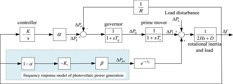
Based on the previous traditional LFC model, a photovoltaic frequency regulation control approach based on the external characteristics of P-U is adopted. Considering the impact of communication delay on photovoltaic grid-connected, the LFC model of power system with photovoltaic (LFC-PV) is constructed, as shown in Figure 2.
Compared with the traditional LFC model in Figure 1, the LFC-PV model adds a photovoltaic frequency regulation control link. This essentially changes the damping of synchronous generators. The control shares of the two circuits are allocated according to a certain proportion coefficient. Among them, photovoltaic power generation circuit assists in frequency regulation control.
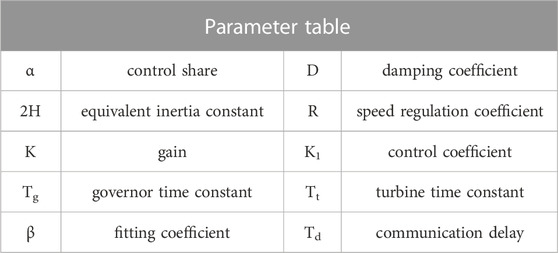
Table 1 lists the parameters involved with the above model.
The state space representation of LFC model is a helpful technique for applying contemporary robust control theories. It may also be employed to provide a basic framework for linear frequency regulation in dynamic frequency analysis that can be readily adjusted and implemented toward any power system. Therefore, the LFC model of a power system incorporating photovoltaic power generation is deduced in this research to investigate the effect of PV upon its performance of the LFC model.
Let the state space expression of the system be:
Where, A is the system matrix, B is the control input matrix,
Considering that there is a certain communication delay
The linear model for the system should be looked into to determine the linear state space model of the system. Figure 2 reveals that the system only has one non-linear component, which is the communication latency link inside the photovoltaic control loop. As a result, in order to derive the linear state space model, it is necessary to linearize the time delay first.
Photovoltaic power system with communication delay
The access of photovoltaic grid-connected has greatly changed the system, and it needs to be equipped with corresponding communication network for control and management. Among them, communication delay is one of the main reasons that affect the stability of power system. The existence of delay will cause the loss or incompleteness of data packets, and make the system deviate in the information transmission, which will seriously affect the stability of the power system.
Given the existence of time delay and exponential term
where,
In this paper, to linearize this system, the fifth order Pade approximation is chosen. After replacing the original pure delay link with a fifth order Pade function, the stability of the system is analyzed.
4 Frequency characteristic evaluation of power system with photovoltaic
In this section, the stability performance of LFC models of power systems with and without PV will be analyzed.
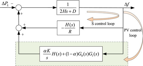
For the convenience of analysis and derivation, the model shown in Figure 2 is simplified to that shown in Figure 3. Load disturbance
Steady state error analysis of system frequency
The primary control loop in Figure 3 adopts frequency dropping control, which is the quickest control mechanism in the power system for modifying frequency (Pourmousavi and Nehrir, 2014). Yet, in the steady state, the frequency deviation does not reach zero. Therefore, photovoltaic control is introduced to engage in auxiliary frequency control via frequency regulation. The impact of the photovoltaic control loop just on stable frequency inaccuracy of the power system is researched in order to evaluate the frequency regulation capabilities of the photovoltaic control loop. According to the simplified model in Figure 3, the system’s frequency deviation could be described as:
where,
Substitute the above formula and arrange it as:
The frequency deviation equation obtained by solving the above formula is:
According to the final value theorem, the steady-state value of the system frequency deviation is:
where,
The following conclusions can be drawn from the above formula:
• The frequency steady-state error of the system is independent of the latency link and the degree of Pade approximation.
• Introducing PV into LFC model to participate in system frequency regulation can improve the reliability of frequency regulation and provide additional degrees of freedom for system frequency regulation. When the auxiliary control is unavailable, if enough photovoltaic resources are available, the photovoltaic control circuit can ensure the performance of system frequency regulation.
• If the system has no PV involved in the control, the frequency error is zero under steady-state conditions.
When photovoltaic power generation is involved in the LFC model, the two control loops are allocated according to the real-time power market cost. As shown in the following formula:
where, in the case of sufficient photovoltaic power generation resources,
Sensitivity analysis of photovoltaic feedback system
Sensitivity refers to the dynamic change amplitude of the system when the relevant parameters of the system are slightly disturbed. By analyzing the sensitivity of the system, it may rapidly and efficiently determine the elements that have a significant impact on the system’s frequency variation, i.e. those key parameters of whole maximum frequency deviation. Adjust relatively sensitive parameters according to the indicators that need to be improved. This will make the regulation of parameters more targeted, provide guidance for the optimization of parameters. When photovoltaic is connected to the power grid, it helps to improve system performance.
Based on the simplified model shown in Figure 3, the closed-loop transfer function between both the system frequency deviation and indeed the load step change is determined.
where,
The typical LFC’s closed-loop transfer function (without photovoltaic) is depicted in Eq. 14. Eq. 15 refers to the closed-loop transfer function when photovoltaic and auxiliary circuits are accessible. The following is the open-loop transfer function only with the primary control.
The following formula may be used to simplify the open-loop system so as to obtain the sensitivity function of closed-loop system.
Where,
This paper mainly studies the trajectory sensitivity function of speed regulation coefficient
Among them,
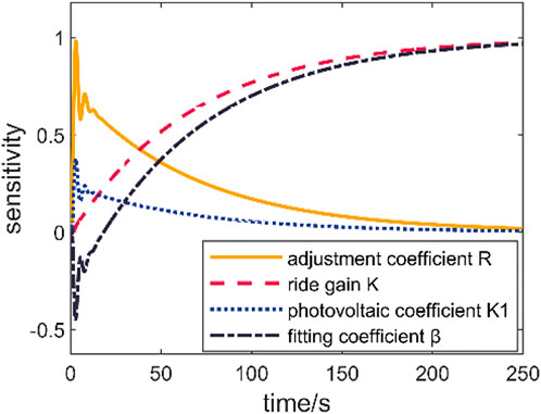
According to the parameter values in Table 1, set the parameters in the sensitivity function to typical values. Frequency disturbance
Comparing the sensitivity curves of different parameters, when t < 15s, the adjustment coefficient is the most sensitive to frequency changes, and the sensitivity of relevant frequency regulation parameters of power system with photovoltaic is low; When 15s < t < 50s, the sensitivity of each parameter changes greatly, and the sensitivity value corresponding to the difference adjustment coefficient decreases continuously. However, it is still highly sensitive to frequency changes, and the sensitivity value corresponding to the control gain and photovoltaic frequency regulation parameters gradually increases. Therefore, the control gain K is considered as the dominant parameter of the maximum frequency deviation. That is, optimizing the control gain K can improve the frequency fluctuation generated by the response system more quickly, and then realize the system frequency adjustment.
From the above analysis, it is further obtained that the adjustment coefficient of the synchronous machine is more sensitive to frequency changes. The primary frequency regulation of the synchronizer can more effectively adjust the frequency deviation and provide active power support for the system. Based on the above conclusions, it can provide guidance for the parameter optimization of the system.
Closed-loop system stability margin analysis
The foundation of efficient feedback control system is system stability. Amplitude margin and phase margin are regularly employed stability assessment parameters. They can measure the reliability and stability of control system intuitively and effectively. The amplitude margin and phase angle margin represent the maximum gain disturbance and the maximum phase disturbance that the control system can withstand when it is stable, respectively, to overcome the disturbance and object uncertainty in the control loop.
The pole of the closed-loop system is the zero point of the characteristic polynomial. As a result, the amplitude and phase margins of the closed-loop system may be derived using the Bode diagram of the open-loop transfer function. The open-loop transfer function is constructed utilizing load disturbance
where,
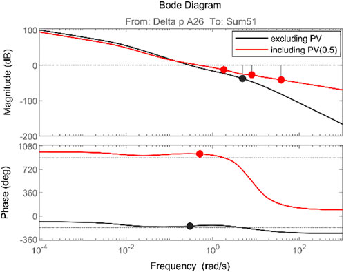
Based on the above formula, the Bode graph of the system’s open-loop function is derived, as illustrated in Figure 5. Figure 5 indicates that the system is generally stable with or without PV involvement.
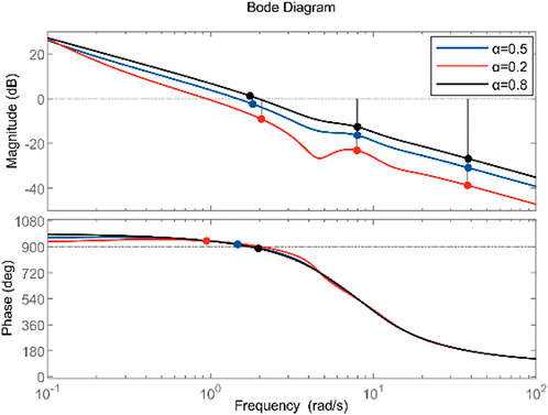
Once the photovoltaic circuit is introduced toward the system, the system gain margin is lowered little, but the phase angle margin is greatly enhanced. In other words, the system’s reliability has strengthened. Photovoltaic involvement in system frequency regulation has a significant influence on the system’s phase angle margin. On this basis, further explore the impact of the proportion of photovoltaic control on system stability. Figure 6 shows that as the share of photovoltaics continues to increase, that is, the larger α, within a certain range, the phase angle margin of the system continues to increase, and the stability gradually improves. However, when the proportion increases to 0.8, the amplitude margin decreases significantly, and the phase angle margin also decreases slightly. That is, the maximum disturbance that the control system can withstand is slightly reduced. This is because the PV participation in frequency regulation increases the stability margin within a certain range, which enhances the stability of the system. But at the same time, the response speed will slow down and the adjustment time will increase. Therefore, the penetration rate of photovoltaic power generation should not be too large to make the system in a suitable margin
Table 2 illustrates the system’s gain and phase angle margins beneath various scenarios. The above conclusions are further verified by the data in the table.
Simulation analysis
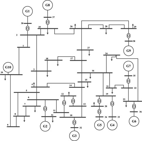
The frequency response simulation system model of the system with photovoltaic is shown in the figure (see Figure 7 on page 12 of the draft). It is a system with 10 generators and 39 bus bars. The generators are synchronous generators, and the classical subtransient model is used to set their capacity to 1000 MW.
At present, China uses photovoltaic as a representative power source for the introduction of new energy. Therefore, in the simulation system, replace five thermal power units with photovoltaic units, simulate the state of the power system when photovoltaic is connected to the grid, and verify the established photovoltaic frequency response model.
According to the 10 machine 39 node system simulation model, the frequency response characteristics of the power system with photovoltaic are analyzed, including five distributed photovoltaic units. This paper assumes that the PV inverter parameters and environmental parameters of distributed PV nodes are similar. Establish the equivalent model of distributed photovoltaic cluster as shown in Figure 2.
The LFC model of a power system with photovoltaic frequency regulation considering communication delay is established via matlab/simulink. Through the simulation and theoretical analysis of the system to explore the impact of system stability. Table 3 below shows the values of the relevant parameters.
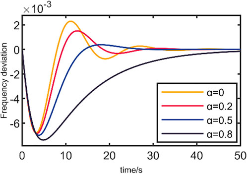
Set the initial disturbance to 0.25pu. Compare the system frequency deviation between the traditional LFC model and the LFC-PV model established above, as indicated in Figure 8.
Figure 8 demonstrates that when Photovoltaics somehow doesn’t engage in system frequency control, system performance is good. The max frequency deviation of the system steadily increases as the proportion of photovoltaic α grows from 0 to 0.8. The overshoot is reduced by about 34.4%. The final frequency deviation tends to zero. When α gradually increases from 0 to 0.5, the time to adjust the frequency to steady state gradually shortens. When α continues to increase to 0.8, the adjustment time is the longest.
The results show that when photovoltaic participates in system frequency regulation, the frequency overshoot caused by disturbance will be reduced. The system can converge faster and make the frequency deviation return to the steady state. However, when the regulation proportion of photovoltaic power generation is too large, the frequency adjustment speed is slow, which poses a threat toward the power grid’s continuous operation. Therefore, the photovoltaic power generation component shall be properly configured to play an effective role in system frequency regulation, which can significantly improve the dynamic performance of the system.
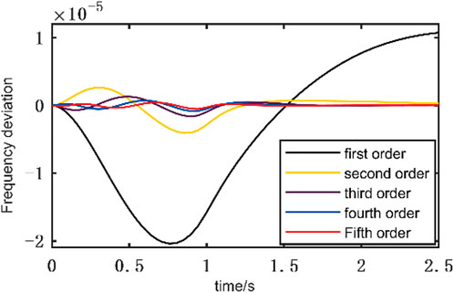
In this paper, the communication delay is taken as 1s. The Pade approximation function of order one to five is selected in turn to linearize the pure delay link. Figure 9 shows the frequency error comparison between Pade approximation function of different orders and pure delay link. When the order of Pade function is 5, the error of the system is the smallest. That is, the fifth order approximation is the closest to the pure delay link, and the approximation accuracy is the best.
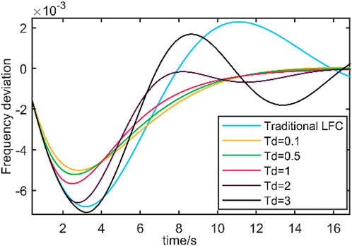
For simulation study, α = 0.8 is chosen to demonstrate the impact of latency on the frequency stability of the system. Figure 10 shows the impact of different communication delays on the system.
It can be seen from the figure that within a certain range, as the communication delay increases, the frequency deviation generated by the system also increases. When the communication delay
The results show that for a small communication delay, the system has certain anti-interference ability and will not have a great impact on the frequency stability. When photovoltaic is introduced to participate in frequency regulation, the adjustment speed is faster. Even in a large communication delay, it still has certain advantages.
Conclusion
This article qualitatively explores the process of photovoltaic power generation engaging in grid frequency regulation through establishing a LFC model of a power system incorporating photovoltaic power generation. The influence of different photovoltaic parameters on the system is revealed. The analysis results show that:
• In this paper, photovoltaic is introduced into the traditional LFC model to participate in frequency regulation. That accelerates system frequency regulation as well as significantly enhances system frequency regulation performance.
• Based on the frequency regulation control strategy of P-U external characteristics, considering the system’s impact of transmission latency, this paper selects the fifth order Pade approximation to linearize the system. It is demonstrated that the fifth degree Pade approximation seems to have little detrimental effect on system stability.
• This research investigates the effect of photovoltaic involvement upon that system’s steady-state frequency error, sensitivity, and stability margin. The influence of photovoltaic participating in system frequency regulation on frequency stability is effectively evaluated.
Data availability statement
The original contributions presented in the study are included in the article/supplementary material, further inquiries can be directed to the corresponding author.
Author contributions
Conceptualization, ZY; Data curation, WH; Formal analysis, FY and RL; Funding acquisition, ZY, WH, and FY; Investigation, WH; Methodology, FY and RL; Project administration, ZY and WH; Resources, ZY, WH, and RL; Software, WH; Supervision, ZY; Validation, FY and RL; Writing—original draft, ZY and RL; Writing—review & editing, FY and RL. All authors have read and agreed to the published version of the manuscript.
Funding
This work was supported by State Grid Corporation of China headquarters science and technology project (No. 5400-202122147A-0-0-00).
Conflict of interest
ZY, WH, and FY was employed by State Grid Hubei Electric Power Company Electric Power Research Institute.
The remaining authors declare that the research was conducted in the absence of any commercial or financial relationships that could be construed as a potential conflict of interest.
The authors declare that this study received funding from State Grid Corporation of China headquarters science and technology project. The funder had the following involvement in the study: Conceptualization, Data curation, Formal analysis, Funding acquisition, Investigation, Methodology, Project administration, and Resources, Software, Supervision, Validation, Writing-original draft, Writing-review & editing.
Publisher’s note
All claims expressed in this article are solely those of the authors and do not necessarily represent those of their affiliated organizations, or those of the publisher, the editors and the reviewers. Any product that may be evaluated in this article, or claim that may be made by its manufacturer, is not guaranteed or endorsed by the publisher.
References
Adetokun, B. B., Muriithi, C. M., and Ojo, J. O. (2020). Voltage stability assessment and enhancement of power grid with increasing wind energy penetration. Int. J. Electr. Power & Energy Syst. 120, 105988. doi:10.1016/j.ijepes.2020.105988
Al-Shetwi, A. Q., Issa, W. K., Aqeil, R. F., Ustun, T. S., Al-Masri, H. M., Alzaareer, K., et al. (2022). Active power control to mitigate frequency deviations in large-scale grid-connected PV system using grid-forming single-stage inverters. Energies 15, 2035. doi:10.3390/en15062035
Bakeer, A., Magdy, G., Chub, A., and Bevrani, H. (2022). A sophisticated modeling approach for photovoltaic systems in load frequency control. Int. J. Electr. Power & Energy Syst. 134, 107330. doi:10.1016/j.ijepes.2021.107330
ChunYi, W., Hong, M., Lu, L., HaoZhong, C., BaoYong, W., and AiHui, Y. (2019). Reliability and stability evaluation of regional power grid under renewable energy and UHV access. J. power Syst. automation 31, 99–104.
Cuello-Polo, G., and O’Neill-Carrillo, E. (2021). Power system modeling for the study of high penetration of distributed photovoltaic energy. Des. (Basel). 5, 62. doi:10.3390/designs5040062
Fu, X., Zhang, X., Guo, Z., Han, F., Wang, J., and Peng, B. (2022). Research on the influence of switching frequency on the stability of large-scale distributed generation system. Energy Rep. 8, 776–784. doi:10.1016/j.egyr.2022.05.198
Gao, Z., Cao, Y., Zhang, H., Qin, H., Yang, D., and Ma, H. (2022). “Virtual inertia control strategy for photovoltaic power generation based on improved incremental conductance method,” in Proceedings of the 2022 7th Asia Conference on Power and Electrical Engineering (ACPEE), Hangzhou, China, 15-17 April.
Jain, A. K., Horowitz, K., Ding, F., Sedzro, K. S., Palmintier, B., Mather, B., et al. (2020). Dynamic hosting capacity analysis for distributed photovoltaic resources—framework and case study. Appl. Energy 280, 115633. doi:10.1016/j.apenergy.2020.115633
Jiang, S., Wan, C., Chen, C., Cao, E., and Song, Y. (2018). Distributed photovoltaic generation in the electricity market: Status, mode and strategy. CSEE J. Power Energy Syst. 4, 263–272. doi:10.17775/cseejpes.2018.00600
Li, R., and Zhang, C. (2021). “A new photovoltaic power station load frequency control strategy,” in Proceedings of the 2021 3rd International Academic Exchange Conference on Science and Technology Innovation (IAECST), Guangzhou, China, 10–12.
Li, Z., Cheng, Z., Si, J., Zhang, S., Dong, L., Li, S., et al. (2021). Adaptive power point tracking control of PV system for primary frequency regulation of AC microgrid with high PV integration. IEEE Trans. Power Syst. 36, 3129–3141. doi:10.1109/tpwrs.2021.3049616
Medina-Quesada Á, , Gil-González, W., Montoya, O. D., Molina-Cabrera, A., and Hernández, J. C. (2022). Control of photovoltaic plants interconnected via VSC to improve power oscillations in a power system. Electronics 11, 1744. doi:10.3390/electronics11111744
Nanou, S. I., Papakonstantinou, A. G., and Papathanassiou, S. A. (2015). A generic model of two-stage grid-connected PV systems with primary frequency response and inertia emulation. Electr. Power Syst. Res. 127, 186–196. doi:10.1016/j.epsr.2015.06.011
Phan-Tan, C. T., and Hill, M. (2021). Decentralized optimal control for photovoltaic systems using prediction in the distribution systems. Energies 14, 3973. doi:10.3390/en14133973
Pourmousavi, S. A., and Nehrir, M. H. (2014). Introducing dynamic demand response in the LFC model. IEEE Trans. Power Syst. 29, 1562–1572. doi:10.1109/tpwrs.2013.2296696
Prakash, V., Bhakar, R., Tiwari, H., and Sharma, K. C. (2018). “Inertia and primary frequency response assessment under uncertain photovoltaic power generation,” in Proceedings of the 2018 8th IEEE India International Conference on Power Electronics (IICPE), Jaipur, India, 13-15 December.
Quan, X., Yu, R., Zhao, X., Lei, Y., Chen, T., Li, C., et al. (2019). Photovoltaic synchronous generator: Architecture and control strategy for a grid-forming PV energy system. IEEE J. Emerg. Sel. Top. Power Electron. 8, 936–948. doi:10.1109/jestpe.2019.2953178
Rezaei, J., Golshan, M. E. H., and Alhelou, H. H. (2022). Impacts of integration of very large-scale photovoltaic power plants on rotor angle and frequency stability of power system. IET Renew. Power Gen. 16, 2384–2401. doi:10.1049/rpg2.12529
Saxena, A., and Shankar, R. (2022). Improved load frequency control considering dynamic demand regulated power system integrating renewable sources and hybrid energy storage system. Sustain. Energy Technol. Assessments 52, 102245. doi:10.1016/j.seta.2022.102245
Schinke, A., and Erlich, I. (2018). Enhanced coltage and frequency stability for power systems with high penetration of distributed photovoltaic generation. IFAC-PapersOnLine 51, 31–36. doi:10.1016/j.ifacol.2018.11.673
Sultan, H. M., Diab, A. A. Z., Kuznetsov, O. N., Ali, Z. M., and Abdalla, O. (2019). Evaluation of the impact of high penetration levels of PV power plants on the capacity, frequency and voltage stability of Egypt’s unified grid. Energies 12, 552. doi:10.3390/en12030552
Tafti, H. D., Konstantinou, G., Fletcher, J. E., Callegaro, L., Farivar, G. G., and Pou, J. (2021). Control of distributed photovoltaic inverters for frequency support and system recovery. IEEE Trans. Power Electron. 37, 4742–4750.
Wu, J., Xing, X., Wu, C., Li, B., Huang, W., Gan, P., et al. (2020). Cyber-enabled intelligence control and security optimization for complex microgrid networks transient frequency stability analysis of power systems considering photovoltaic grid connection. Complexity 2020, 1–10. doi:10.1155/2020/5641596
Yan, G., Liang, S., Jia, Q., and Cai, Y. (2019). Novel adapted de-loading control strategy for PV generation participating in grid frequency regulation. J. Eng. (Stevenage). 2019, 3383–3387. doi:10.1049/joe.2018.8481
You, S., Liu, Y., Tan, J., Gonzalez, M. T., Zhang, X., Zhang, Y., et al. (2018). Comparative assessment of tactics to improve primary frequency response without curtailing solar output in high photovoltaic interconnection grids. IEEE Trans. Sustain. Energy 10, 718–728. doi:10.1109/tste.2018.2846233
Keywords: photovoltaic, load frequency control, power system, communication delay, frequency stability
Citation: Yang Z, Hu W, Yang F and Liu R (2023) Frequency stability analysis of power system with photovoltaic frequency regulation considering communication delay. Front. Energy Res. 10:1041841. doi: 10.3389/fenrg.2022.1041841
Received: 11 September 2022; Accepted: 01 December 2022;
Published: 01 February 2023.
Edited by:
Yanhong Luo, Northeastern University, ChinaReviewed by:
Rui Wang, Northeastern University, ChinaChunbin Qin, Henan University, China
Bowen Zhou, Northeastern University, China
Copyright © 2023 Yang, Hu, Yang and Liu. This is an open-access article distributed under the terms of the Creative Commons Attribution License (CC BY). The use, distribution or reproduction in other forums is permitted, provided the original author(s) and the copyright owner(s) are credited and that the original publication in this journal is cited, in accordance with accepted academic practice. No use, distribution or reproduction is permitted which does not comply with these terms.
*Correspondence: Ruifan Liu, MTAyMTA1MTcwNEBuanVwdC5lZHUuY24=
 Zhichun Yang1
 Ruifan Liu
