 Zaifa Chen1,2*
 Yancheng Liu1
- 1Maritime Engineering College, Dalian Maritime University, Dalian, China
- 2Zhejiang International Maritime College, Zhoushan, China
Gross error interference or noise statistical deviation is the main factor that leads to the accuracy deterioration of extended Kalman filter (EKF) in estimating the speed and rotor position of ship propulsion permanent magnet synchronous motor (PMSM). In this paper, an adaptive extended Kalman filter (AEKF) algorithm based on innovation sequence is proposed. In the proposed method, gross error interference is first added to EKF to analyze its influence on the observation accuracy. Then, the weighting coefficient is set in the calculation of innovation covariance. By adjusting the weight of the innovation covariance matrix at the adjacent time, the innovation covariance difference is calculated and then used in the calculation of Kalman gain. The observation performance comparison between AEKF and EKF strategies is conducted with subject to gross error interference and noise statistics deviate. Simulation and experimental results demonstrate that the proposed AEKF has stronger robustness and higher prediction accuracy of speed and rotor position.
1 Introduction
The propulsion motor is the hard-core components of ship electric propulsion system, high power permanent magnet synchronous motor, with the advantages of high efficiency, high power density, good control performance, is widely used in compact podded propeller. Traditional PMSM control systems typically use mechanical sensors to obtain the rotor position and speed of the motor. However, the use of sensors not only increases the cost, but also brings the problem of reliability deterioration. Therefore, sensorless control has become an important research direction of PMSM control system. The sensorless control methods of PMSM can be classified into model reference adaptive (Lin et al., 2017), sliding mode observer (Liang et al., 2017; He et al., 2020), Lomberg observer (Wu et al., 2016), full order observer (Wang et al., 2019), extended Kalman filter, etc. (Luo and Luo 2019; Shi and Qi, 2020; Li and Kennel, 2021).
Extended Kalman filter (EKF) is an iterative algorithm based on minimum variance. In recent years, the development of high-speed processors has solved the problem of the large amount of EKF calculation, and is widely used in sensorless vector control systems. As an iterative discrete calculation method, EKF uses the state prior estimation and measurement feedback of the system, and then adjusts the Kalman gain matrix in real time to obtain the posterior estimation value of the infinite approximation system state truth value at this time. Compared with other observation algorithms, EKF has the advantages of wide speed range and strong immunity, so it has become a hot spot in the research of motor state estimation.
The estimation accuracy of EKF is related to the selection of Kalman gain matrix, system and measurement noise covariance matrix. In recent years, many methods have been proposed to improve the estimation accuracy and immunity of EKF. References (Wang et al., 2019; Li and Kennel, 2021) improve the observation performance of EKF by establishing dead time compensation or nonlinear compensation system at the output of inverter to eliminate the influence of current harmonic and voltage loss on the input of EKF. The experimental results show that the compensated EKF has stronger state estimation performance. References (Luo and Liu, 2019) optimizes the calculation process of the covariance matrix of the system and measurement noise based on genetic algorithm, which reduces the calculation difficulty of the covariance matrix value and the anti-interference ability of the system. References (Yin et al., 2016; Yi et al., 2014; Lu and Xu, 2009) reduced the parallel price of EKF to reduce the complexity of the algorithm while maintaining the performance of EKF. References (Zerdali, 2019; Özkurt and Zerdali, 2022) established an adaptive mechanism to compensate for the influence of the changing system noise covariance matrix on the observation performance. Reference (Deng et al., 2019; Miguel-Espinar et al., 2021) proposed a robust EKF algorithm, which makes adjustment rules for the ratio of estimation error to external interference under interference. The results show that this kind of method has stronger anti-interference performance than the unmodified EKF under disturbance.
In order to improve the prediction accuracy of EKF in the case of noise statistics bias and gross error interference, in this paper, an adaptive Kalman filter algorithm based on innovation sequence is proposed. In the proposed method, the influence of gross error on system observation is first analyzed, and then the weighting factor is introduced to formulate the calculation rules of innovation covariance matrix, which is also used in the calculation of Kalman gain. The simulation results show that the adaptive EKF has higher robustness and observation accuracy for speed observation under gross error interference.
The reminder of this paper is organized as follows: Section 2 introduces the mathematical model of PMSM and the principle of extended Kalman filter. Section 3 presents the design details of adaptive extended Kalman filter (AEKF) algorithm based on innovation sequence. The feasibility simulation and physical verification of AEKF algorithm based on permanent magnet synchronous motor are carried out in Sections 4, 5. A conclusion is given in Section 6.
2 Extended Kalman filter
2.1 Mathematical model of permanent magnet synchronous motor
Ignoring core saturation, eddy current and hysteresis losses, the PMSM current equation can be expressed as:
where
Combining Eq. 1, establish the PMSM state equation and observation equation as follows:
Where,
2.2 Extended Kalman filter principle
EKF is the application of Kalman filter in nonlinear systems. It is an optimal state estimation method in the sense of minimum variance. In the vector control system based on EKF, it is necessary to linearize and discretize the motor equation of PMSM. Combined with Eq. 1, the extended Kalman state equation is established as follows.
where
The specific implementation steps of EKF algorithm are as follows:
1) State predictive value estimation
2) Error covariance matrix estimation
where,
3) Kalman gain matrix calculation
4) State estimation correction
5) Update error covariance matrix
where I is the unit matrix, Kk|k-1 is the Kalman gain matrix, Fk|k-1 is the Jacobian matrix of the state matrix
3 Adaptive extended Kalman filter strategy
3.1 Influence of gross error on adaptive extended Kalman filter
EKF is an optimal observation algorithm based on the accurate system modeling. In the actual operation process, the observation module is often disturbed by external variables of non-Gaussian white noise. When there is interference in the observation, the observation equation of the system can be expressed as:
where
On the basis of EKF, AEKF adjusts the weight of innovation sequence to eliminate the influence of gross error on parameter estimation. In this process, innovation sequence is introduced to improve EKF. The innovation sequence with gross error interference is expressed as:
where
In the observation interval with a time length of
The observation equation of the system obeys Gaussian distribution, and the optimal estimation value of Eq. 12 is verified based on the maximum likelihood estimation method hypothesis
Taking logarithms of Eq. 13 respectively to obtain the following equation:
where
Taking the derivative of pair
Find the partial derivative of Eq. 16 with respect to parameter
From Eq. 17, it can be seen that Eq. 12 is the optimal estimate of the information covariance matrix C in the interval with a length of K. Considering the influence of gross error interference on Kalman gain calculation, re-integrate Eq. 12 and Eq. 6 and re-derive the Kalman gain matrix
According to Eq. 18, in the process of speed observation, gross error affects the Kalman gain matrix by changing the innovation process, which affects the state estimation of the whole system, but this method fails to improve the utilization weight of recent data. In order to improve the observation performance in the case of gross error and statistical information deviation, an adaptive extended Kalman algorithm is designed to weaken the influence of the above interference on the observer performance by increasing the proportion of the covariance matrix of the innovation sequence at the latest time.
3.2 Establishment of adaptive extended Kalman filter algorithm
First, the gross error is introduced into the observation equation, and the equation is established as follows:
Then, the innovation estimation covariance sequence with length N is selected. When
For the innovation estimation covariance matrix at time k, the weighting coefficient of Eq. 20 is introduced to obtain:
Similarly, at time
From Eqs 16, 17, we can get the recursive form of the exponentially weighted innovation covariance matrix as:
A new calculation method of Kalman gain matrix is obtained by substituting Eq. 23 into Eq. 18. This method formulates exponential weighting rules on the selection of innovation covariance matrix, and improves the weight of recent data in the calculation of Kalman gain matrix. Compared with the calculation method of taking the average value of Eq. 12, it has the advantage of high estimation accuracy. AEKF based on exponential weighting rules can be expressed as follows:
Based on Eq. 24, a PMSM sensorless vector control system based on AEKF is built, and the system structure is shown in Figure 1. The control loop is composed of an outer speed loop and an inner current loop, in which the speed error is taken as the given value of the q-axis current through the sliding mode controller; The error signal between the current and the given current in the static coordinate system is modulated by PI as the given value of d-axis and q-axis voltage. The input of AEKF is the current and voltage in the static coordinate system, and the output speed and rotor position.
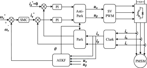
FIGURE 1. Control block diagram of AEKF.
4 Simulation results
Parameters of PMSM used in simulations and experiments are shown in Table 1. The simulation speed is n = 1,200 r/min and the simulation interval is 1 s.
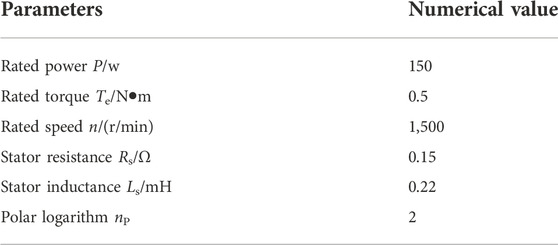
TABLE 1. The parameters of PMSM.
In order to verify the feasibility of AEKF algorithm, simulation experiments are as follows. The current regulator adopts the form of PI regulator, with a proportional coefficient of 0.3 and an integral coefficient of 10. Considering that the change of load torque will have an impact on the whole control system, the motor speed will change significantly when the load is suddenly increased or decreased, and it will take some time to recover to the given speed, in order to maintain the stability of the ship’s traveling process, the impact of the change of load torque on the ship’s electric propulsion control system should be reduced. The speed regulator adopts sliding mode controller (SMC), the sliding mode surface is the angular velocity error of the motor, and the control law adopts the improved constant speed approach law. Through experimental comparison, the PI controllers of both sides have the same parameter settings as SMC, and the system adopts the vector control strategy with id = 0.
In the motor loading experiment, 0.5 N•m load was suddenly applied at the time of t = 0.2 s. Figure 2 shows the speed error waveform of the two control strategies in response to the sudden load change, and Figure 3 shows the rotor position and position error waveform. It can be seen from the simulation waveform that when the load changes suddenly, the error of speed estimation of AEKF is lower, and the rotor position observation has stronger stability.
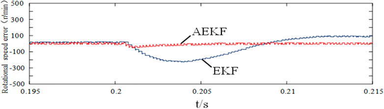
FIGURE 2. Speed error under sudden load change.
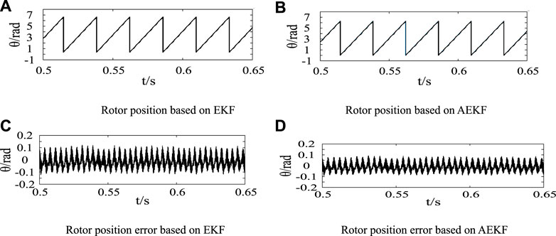
FIGURE 3. Comparison of rotor position under load change. (A) Rotor position based on EKF. (B) Rotor position based on AEKF. (C) Rotor position error based on EKF. (D) Rotor position error based on AEKF.
When t = 0.6 s, suddenly add 1 A current to iα The external gross error interference in speed estimation is simulated. Figure 4 shows the speed error comparison curve of the two strategies under gross error interference, and Figure 5 shows the rotor position and position error comparison diagram of the two strategies. It can be seen from above figures that both strategies will have speed error waveform when encountering interference, but the fluctuation of AEKF encountering external interference is lower, and the rotor position observation performance is more stable and has stronger immunity.
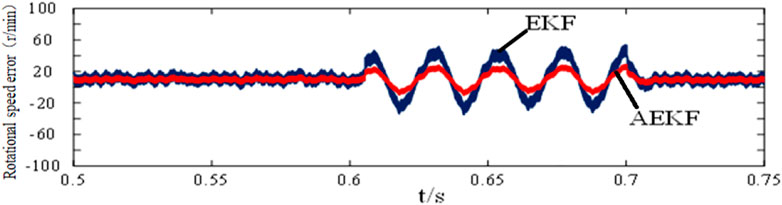
FIGURE 4. Speed error with external disturbance.
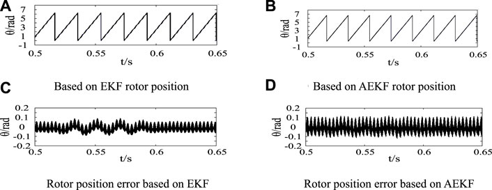
FIGURE 5. Comparison of rotor position under external interference. (A) Based on EKF rotor position. (B) Based on AEKF rotor position. (C) Rotor position error based on EKF. (D) Rotor position error based on AEKF.
In order to verify the anti-interference performance of the algorithm to the internal error disturbance, the error signal of x = [0 1 0 0]T is added to the input of the observer at the time of t = 0.6 s. The experimental results are shown in Figure 6 and Figure 7. Under the interference of internal error signal, the fluctuation amplitude of AEKF is smaller than that of EKF, there is no obvious waveform in the rotor position error curve, and the speed and rotor position tracking performance of AEKF is better.
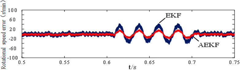
FIGURE 6. Speed error with internal disturbance.
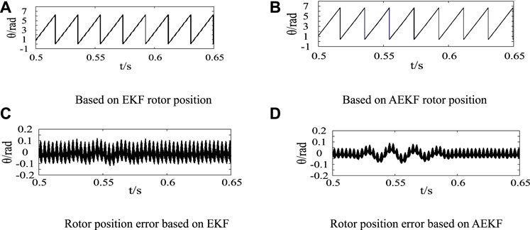
FIGURE 7. Comparison of rotor position under internal interference. (A) Based on EKF rotor position. (B) Based on AEKF rotor position. (C) Rotor position error based on EKF. (D) Rotor position error based on AEKF.
The following figure shows the rotor position curve of the two control strategies under internal interference. It can be seen from the enlarged diagram of rotor position error in Figures 7A,C and Figures 7B,D that the rotor position observation disturbance of AEKF is lower.
5 Experimental verification
The EKF and AEKF strategies are compared and verified on the experimental platform shown in Figure 8. The STM32F446 chip of Italian semiconductor is used in the main control board, and the hall encoder is used to obtain the actual speed. The observed speed, actual speed and motor current of the motor are monitored through the upper computer and oscilloscope. The experimental speed is set at 1,200 r/min, and the anti-interference performance and load performance of the algorithm are compared and analyzed for two different control algorithms.
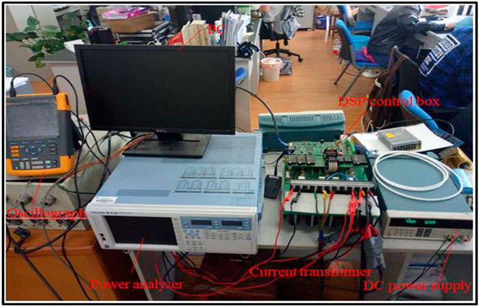
FIGURE 8. Experimental platform.
5.1 Loading dynamic performance experiment
Figure 9 and Figure 10 show the experimental comparison of two algorithms of sudden load on the motor when the motor speed is 1,200 rpm. As shown in above figures, under loading, the phase current variation of AEKF is lower, the error between the observed speed and the actual speed of the observer is smaller, and the speed tracking performance is stronger. In terms of rotor position observation, both control strategies can accurately follow the actual rotor position.
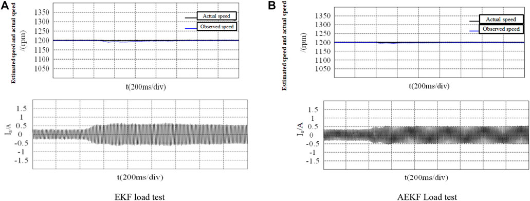
FIGURE 9. Speed waveform of torque step response. (A) EKF load test. (B) AEKF Load test.
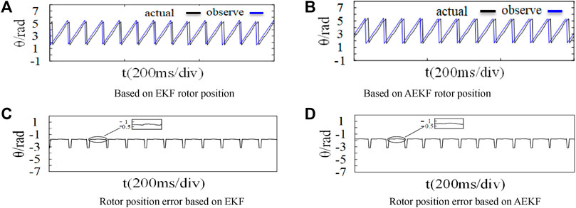
FIGURE 10. Rotor position waveform of torque step response. (A) Based on EKF rotor position. (B) Based on AEKF rotor position. (C) Rotor position error based on EKF. (D) Rotor position error based on AEKF.
5.2 Dynamic performance test of unloading
Figure 11 and Figure 12 show the data after unloading the load when the motor is loaded and operates stably at 1,200 r/min. It can be seen from above figures that under the condition of sudden unloading of the motor, the overshoot of the speed reference actual value observed by AEKF is lower, and the following performance of the actual speed is stronger. In terms of rotor position estimation, both have the same performance, and can accurately follow the actual position.
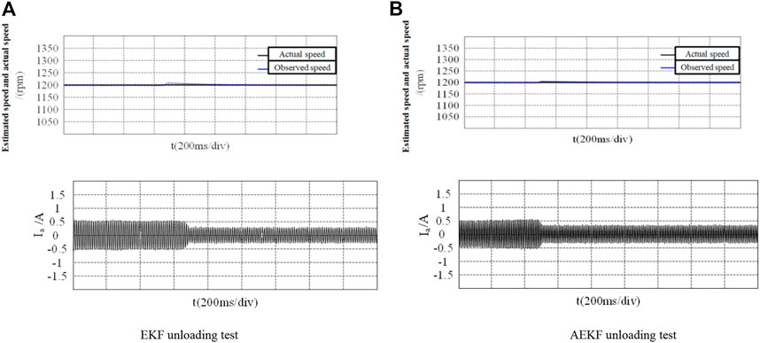
FIGURE 11. Speed waveform of unload torque. (A) EKF unloading test (B) AEKF unloading test.
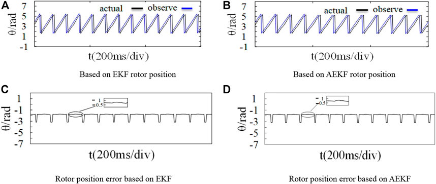
FIGURE 12. Rotor position waveform of unload torque. (A) Based on EKF rotor position. (B) Based on AEKF rotor position. (C) Rotor position error based on EKF. (D) Rotor position error based on AEKF.
5.3 External interference experiment
The current sampling resistance of the motor control board shown in Figure 8 is 0.02 Ω. In the external interference experiment, adding 1 A interference signal to the input of the observer can be equivalent to superimposing 0.02 v voltage on both ends of the sampling resistance of the control board to simulate the influence of 1 A current interference on the Clark transform input. Figure 13 and Figure 14 show the comparison of the observer performance of the two algorithms after external interference. It can be seen from above figures that AEKF has smaller offset of observed speed, lower current ripple and stronger immunity in the face of external interference. In rotor position observation, both algorithms can track the actual position signal when interference occurs, but the position error of AEKF is smaller than that of EKF.
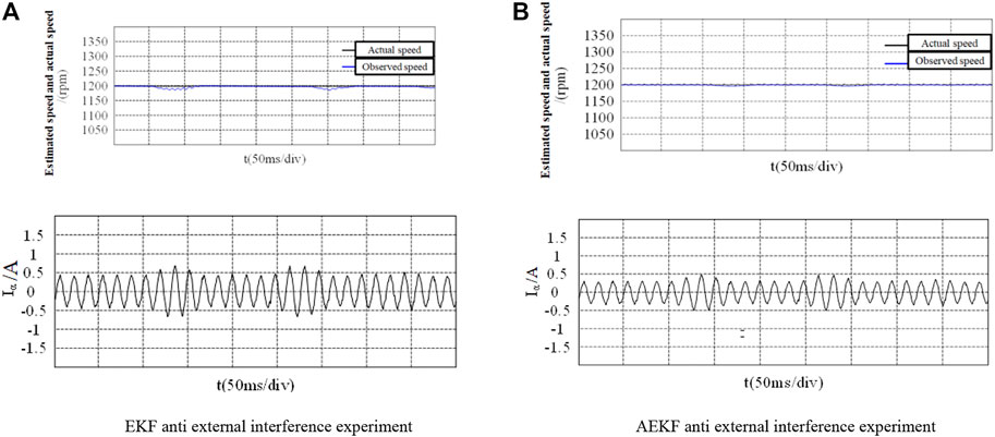
FIGURE 13. Speed waveform under external interference. (A) EKF anti external interference experiment (B) AEKF anti external interference experiment.
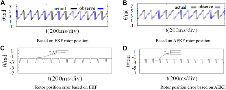
FIGURE 14. Rotor position waveform under external interference. (A) Based on EKF rotor position. (B) Based on AEKF rotor position. (C) Rotor position error based on EKF. (D) Rotor position error based on AEKF.
5.4 Internal interference experiment
Similar to the external interference experiment, in the program operation, set the time when the interference variable is added to EKF through the internal timer TIM2 of STM32, by adding [1,1] disturbances to the inputs
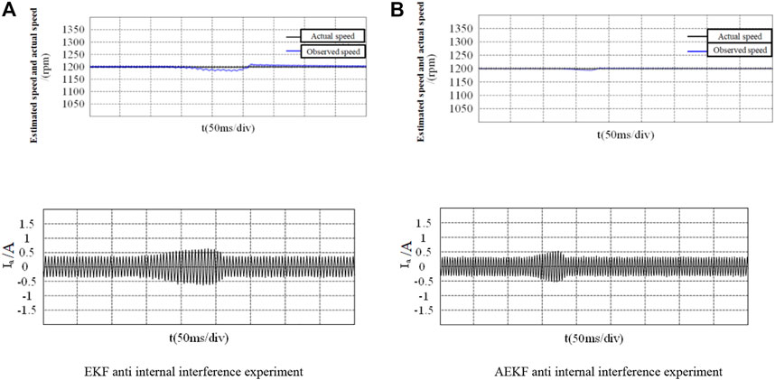
FIGURE 15. Speed waveform under internal interference. (A) EKF anti internal interference experiment. (B) AEKF anti internal interference experiment.
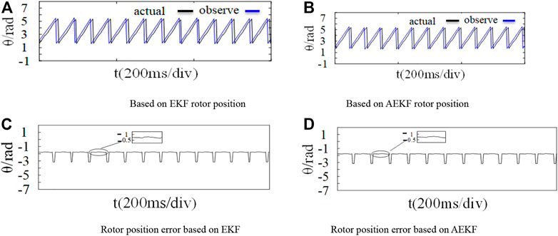
FIGURE 16. Rotor position waveform under internal interference. (A) Based on EKF rotor position. (B) Based on AEKF rotor position. (C) Rotor position error based on EKF. (D) Rotor position error based on AEKF.
6 Conclusion
This paper proposes a sensorless control method of PMSM based on adaptive extended Kalman filter. Firstly, the principles of AEKF and EKF are introduced, and the differences between them are analyzed. Compared with EKF, AEKF has higher observation accuracy of speed and stronger anti-interference ability in the case of gross error interference and noise statistical deviation. In terms of rotor position estimation, the performance of the two control strategies is the same. Finally, the dynamic and static performances of the two are compared and analyzed through simulation and experiment. The simulation and experimental results demonstrate that AEKF can significantly reduces the speed estimation error and has stronger anti-interference ability in the case of sudden load change, gross error interference and noise statistical deviation, and which can meet the needs of ship electric propulsion system in complex environment.
Data availability statement
The raw data supporting the conclusion of this article will be made available by the authors, without undue reservation.
Author contributions
ZC and YL proposed the scheme and wrote the manuscript. ZC designed and carried out experiments. Both authors contributed to the article and approved the submitted version.
Funding
This study was aided by the natural science foundation of Zhejiang Province under Grant no. LGG20E070001.
Conflict of interest
The authors declare that the research was conducted in the absence of any commercial or financial relationships that could be construed as a potential conflict of interest.
Publisher’s note
All claims expressed in this article are solely those of the authors and do not necessarily represent those of their affiliated organizations, or those of the publisher, the editors and the reviewers. Any product that may be evaluated in this article, or claim that may be made by its manufacturer, is not guaranteed or endorsed by the publisher.
References
Deng, T., Su, Z., Lin, J., Tang, P., Chen, X., and Liu, P. (2019). Adv-anced angle field weakening control strategy of permanen-t magnet synchronous motor. IEEE Trans. Veh. Technol. 68, 3424–3435. doi:10.1109/TVT.2019.2901275
He, L., Wang, F., Wang, J., and Rodríguez, J. (2020). Zynq implemented luenberger disturbance observer based predictive control scheme for PMSM drives. IEEE Trans. Power Electron. 35 (2), 1770–1778. doi:10.1109/TPEL.2019.2920439
Jin, W. W., Jian-hui, S., Peng, L., and Hai-ning, W. (2016). De-sign of full-order flux observer and comparision analysis for its control performance. Electr. Mach. Con-trol 20 (04), 78–83. doi:10.15938/j.emc.2016.04.011
Li, X., and Kennel, R. (2021). General formulation of kalman-filter-based online parameter identification methods for VSI-fed PMSM. IEEE Trans. Ind. Electron. 68 (4), 2856–2864. doi:10.1109/TIE.2020.2977568
Liang, D., Li, J., and Qu, R. (2017). Sensorless control of permane-nt magnet synchronous machine based on second-order sliding mode observer with online resistance estimation. IEEE Trans. Industry Appl. 53 (4), 72–82. doi:10.16182/j.issn1004731x.joss.201712027
Lin, M., Li, Y., Chen, W., Yuan, G., and Chen, L. (2017). AModel reference adaptive system based sliding mode O-bserver for model predictive controlled permanent MagnetSynchronous motor drive. Trans. China Electr-otechnical Soc. 32 (06), 156–163. doi:10.19595/j.cnki.1000-6753.tces.2017.06.018
Lu, H. C., and Xu, Y. T. (2009). Speed and position estimation A-lgorithm of permanent magnet linear synchronous motor based on augmented extended kalman filter. Procee-dings CSEE 29 (33), 90–94. CNKI:SUN:ZGD-C.0.2009-33-017. doi:10.13334/j.0258-8013.pcsee.2009.33.006
Luo, Y., and Liu, C. (2019). Multi-vector-based model predictive torque control for a six-phase PMSM motor with fixed switching frequency. IEEE Trans. Energy Convers. 34 (3), 1369–1379. doi:10.1109/TEC.2019.2917616
Miguel-Espinar, C., Heredero-Peris, D., Gross, G., Llonch Masachs, M., and Montesinos-Miracle, D. (2021). Maximum torque- per voltage flux-weakening strategy with speed limiter fo-r PMSM drives. IEEE Trans. Ind. Electron. 68 (10), 9254–9264. doi:10.1109/TIE.2020.3020029
Özkurt, G., and Zerdali, E. (2022). Design and implementation of hybrid adaptive extended kalman filter for state estimation of induction motor. IEEE Trans. Instrum. Meas. 71, 1–12. doi:10.1109/tim.2022.3144729
Shi, W., and Qi, R. (2020). Parameter identification of permanent-magnet motor thermal network based on extended kalmanfilter[J]. J. Electr. Mach. Control 24 (12), 112–116. doi:10.15938/j.emc.2020.12.013
Wang, D. F., Li, Q., Zhang, P., and Jin, Y. (2019). Speed estimati-on method based on extended Kalman filter with phase voltage compensation for sensorless ACIM drives. Electri-c Mach. Control 23 (01), 35–44. doi:10.15938/j.emc.2019.01.005
Wang, Y., Feng, Y., Qin, M., and Li, M. (2018). Full-order sliding mode observation and control strategy for surface permanent magnet synchronous motor [J]. Transa-ctionsof China Electrotech. Soc. 33 (24), 88–99. doi:10.19595/j.cnki.1000-6753.tces.181133
Wu, W-j., Su, J-h., Liu, P., and Wang, H-n. (2016). Design of full-order flux observer and comparision analysis for its control performance. Electr. Mach. Control. 20 (04), 78–83. doi:10.15938/j.emc.2016.04.011
Yang, H., Yang, R., Hu, W., and Huang, Z. (2021). FPGA-based sensorless speed control of PMSM using enhanced perfo-rmance controller based on the reduced-order EKF. IEEE J. Emerg. Sel. Top. Power Electron. 9 (1), 289–301. doi:10.1109/JESTPE.2019.2962697
Yi, B., Kang, L., Tao, S., Zhao, X., and Guo, H. (2014). Observer design of interior permanent magnet S-ynchronous motors based on two-stage kalman filter [J]. Trans. China Electrotech. Soc. 29 (09), 110–118. doi:10.19595/j.cnki.1000-6753.tces.2014.09.017
Yin, Z., Lu, X., Sun, X., Liu, J., and Zhong, Y. (2016). A speed estimation method of fuzzy extended ka-lman filter for induction motors based on particle swar-m optimization. Trans. China Electrotech. Soc. 31 (06), 55–65. doi:10.19595/j.cnki.1000-6753.tces.2016.06.007
Zerdali, E. (2019). Adaptive extended kalman filter for speed-sensorless control of induction motors. IEEE Trans. Energy Convers. 34 (2), 789–800. doi:10.1109/TEC.2018.2866383
Keywords: permanent magnet synchronous motor (PMSM), rotor position and speed estimation, adaptive extended Kalman filter (AEKF), vector control (VC), sensorless control
Citation: Chen Z and Liu Y (2022) Sensorless control of marine permanent magnet synchronous propulsion motor based on adaptive extended Kalman filter. Front. Energy Res. 10:1037595. doi: 10.3389/fenrg.2022.1037595
Received: 06 September 2022; Accepted: 21 October 2022;
Published: 24 November 2022.
Edited by:
Guibing Zhu, Zhejiang Ocean University, ChinaReviewed by:
Zhang quzhou, Shanghai Maritime University, ChinaHongfen Bai, Shanghai Maritime University, China
Chaoming Huang, Jimei University, China
Copyright © 2022 Chen and Liu. This is an open-access article distributed under the terms of the Creative Commons Attribution License (CC BY). The use, distribution or reproduction in other forums is permitted, provided the original author(s) and the copyright owner(s) are credited and that the original publication in this journal is cited, in accordance with accepted academic practice. No use, distribution or reproduction is permitted which does not comply with these terms.
*Correspondence: Zaifa Chen, Y2hlbnphaWZhMzY4QDE2My5jb20=