 Jiansong Zhang
 Yongsheng Liu
 Xing Qin2
- 1Key Laboratory of Deep Geological Drilling Technology of Ministry of Natural Resources, School of Engineering and Technology, China University of Geosciences, Beijing, China
- 2Sinopec Research Institute of Petroleum Engineering, Beijing, China
As a renewable energy source, geothermal energy has drawn attention because it is clean, low-carbon, resource-rich, stable, and sustainable supply. In the mining and operation of a geothermal energy system, there is a certain amount of fluid resistance in the borehole heat exchanger where the fluid flows. As the resistance in the conventional borehole heat exchanger (CBHE) accumulates with the length increase, the pumping power increases, resulting in energy loss and affecting the operation of the entire geothermal system. A bionic borehole heat exchanger (BBHE) is designed using a circular groove as a bionic unit based on the bionic non-smooth surface hypothesis. Its structural characteristics are the circular groove’s depth, width, and slot pitch. Where the fluid faces the least resistance, minimization of the pressure drop was the optimization goal. Based on the outcomes of a CFD numerical simulation and genetic algorithm optimization study. These are the BBHE’s ideal structural parameters: diameter is 60 mm, 66 mm for the groove width, 418 mm for the slot pitch, and 80 mm for the groove depth. Compared to the CBHE, under identical numerical simulation settings, the fluid resistance reduction rate of BBHE can reach 13%. Increasing fluid velocity in the BBHE can increase the temperature transmission rate. The study’s findings can serve as a reliable source of scientific information for the use and management of geothermal energy.
1 Introduction
With the decrease of fossil fuel reserves and the aggravation of environmental degradation brought by the development, renewable energy and pollution-free new energy has attracted people’s attention (Jurasz et al., 2020; Vakulchuk et al., 2020). Geothermal energy, a kind of renewable energy, has the advantages of low carbon, abundant resources, stable and continuous supply, direct utilization without conversion, and a high utilization rate (van der Zwaan and Dalla Longa, 2019; Aghahosseini and Breyer, 2020). Using the borehole heat exchanger is necessary when exploiting geothermal energy. Currently, the borehole heat exchanger is mainly used as coaxial vertical, horizontal single-branch, horizontal multi-branch and U-shaped (Cui et al., 2017; Gharibi et al., 2018; Nian and Cheng, 2018). The energy consumption of circulating pumps and other peripheral pipeline equipment in geothermal systems is quite large due to internal resistance, which accounts for more than 10% of the total power input (Lim et al., 2017). Therefore, it can be seen that reducing the internal resistance of peripheral pipeline equipment in geothermal systems can avoid a lot of energy consumption. When fluid flows through borehole heat exchangers, heat and power generation increase with the flow velocity, which largely depends on fluid flow velocity (Daneshipour and Rafee, 2017). Therefore, it can be seen that the resistance of borehole heat exchangers to the fluid can directly affect a geothermal system’s heat and power generation. The fluid flow rate in the U-shaped borehole heat exchanger will also affect the heat and power generation of the whole geothermal system (Bouhacina et al., 2015). In the multi-branch well-enhanced geothermal system, when the working fluid comes out of the production well and returns to the ground through the borehole heat exchanger in the main wellbore, the faster the working fluid returns, the less heat loss (Song et al., 2018). Therefore, it can be seen that the fluid flow velocity in the borehole heat exchanger will directly affect the heat and power generation of the geothermal system. As shown in Figure 1, in the mining and operation of a geothermal energy system, when the fluid flows through the surface pipe and underground borehole heat exchanger, there is a specific resistance in the surface pipe and underground borehole heat exchanger. The fluid resistance in the underground borehole heat exchanger will gradually accumulate with the increase of the length of the borehole heat exchanger (Alimonti et al., 2018; Iry and Rafee, 2019; He and Bu, 2020). As a result, pumping power increases, resulting in energy loss and affecting the operation of the entire geothermal system.
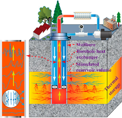
FIGURE 1. Schematic diagram of geothermal system operation.
The structure of borehole heat exchanger is round tube. Resistance in the round tube is not conducive to fluid delivery. Many scholars have studied reducing fluid resistance in the round tube (Asidin et al., 2019; Zabihi et al., 2019). The most common method is to add a variety of drag reduction agents to the fluid flowing through the round tube, which can reduce the pressure drop through the round tube and thus reduce energy consumption (Chai et al., 2019; Moayedi et al., 2020; Yuan et al., 2022). However, adding additives is not suitable to solve the problem of conventional borehole heat exchanger fluid resistance in geothermal production. Because this method may pollute and destroy the underground environment. Therefore, bionic drag reduction technology improves the existing conventional borehole heat exchangers (CBHE). After hundreds of millions of years of evolution and adaptation, organisms have formed their body surface morphology and structural characteristics that can be in harmony with nature, showing maximum adaptability to the natural environment (Sun and Bhushan, 2018; Cya et al., 2020). Many academics now identify the “second vortex group” hypothesis and the “bulky height” theory as the two primary drag reduction processes of bionic non-smooth surfaces (Bacher and Smith, 1985; Dean and Bhushan, 2010).
The main research objective is to introduce the biomimetic non-smooth surface theory into CBHE to reduce fluid drag. The suggested bionic borehole heat exchanger (BBHE) model is based on the bionic non-smooth surface drag reduction technology. In other words, the internal flow channel surface of the traditional borehole heat exchanger is uniformly added with a circular groove as the bionic unit under a specific rule. To a certain extent, it can effectively improve the hydraulic characteristics of the internal flow channel of the CBHE. The theoretical for a pressure drop of BBHE is derived from the current pressure drop formula of variable cross-section construction with tube diameter reduction or diameter expansion. For the specific BBHE pressure drop calculation example, the minimum pressure drop is taken as the optimization objective. The basic structural parameters of BBHE, such as groove depth, width and slot pitch, were optimized by a genetic algorithm. BBHE’s drag reduction properties were examined in more detail when combined with CFD numerical simulation. The study’s findings can serve as a reliable source of scientific information for the use and management of geothermal energy. At the same time, it provides a new idea and method for round-tube drag reduction.
2 Method of modeling and optimization
2.1 A conceptual model for BBHE
The bionic non-smooth surface drag reduction technology lowers drag on non-smooth surfaces based on the bionics principle, which substantially impacts the fluid’s boundary layer (Liu et al., 2020; Yu et al., 2020). The main focus of research on this reduction technology is various rib surfaces (Walsh, 1982; Choi, 1989). The effectiveness of the rib drag reduction approach in lowering fluid resistance has been demonstrated in a variety of industries (Wilkinson et al., 1988; Liu et al., 2018). In this study, we presented a new BBHE based on the standard L-shaped rib, and the schematic diagram is displayed in Figure 2.
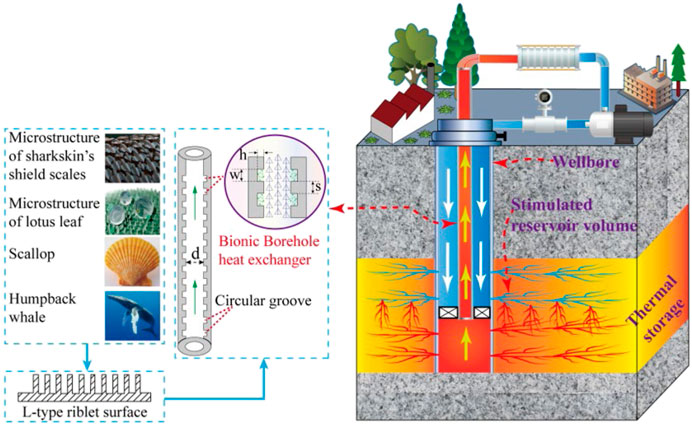
FIGURE 2. Conceptual illustration of a BBHE.
The mastoid structure of a lotus leaf, the spherical nodules structure of a humpback whale’s flippers, the radial stripes of a scallop, and the shield scales of sharkskin are among the typical bionic prototypes of non-smooth surfaces, as depicted in Figure 2. In addition, d stands for diameter (m), h stands for groove depth (m), w stands for groove width (m), and s stands for slot pitch (m). The drag reduction idea of bionic non-smooth surfaces serves as the foundation for the proposed BBHE model. It can enhance the fluid’s kinematic and dynamic properties as it flows against the pipe wall.
2.2 A Single-Type and Comprehensive-Type modeling structure
A shrinkage or expansion structure is the only circular tube with a changing cross-sectional design, as depicted in Figure 3A (Ibrahim and Hashim, 1994; Zhao et al., 1999; Chen et al., 2010). A shrinkage-expansion or expansion-shrinkage structure is the only kind of circular tube with a changing cross-sectional design, as depicted in Figure 3B (Hermany et al., 2013; Dos Santos et al., 2014). The structure has an established formula for estimating pressure decrease in a Newtonian fluid.
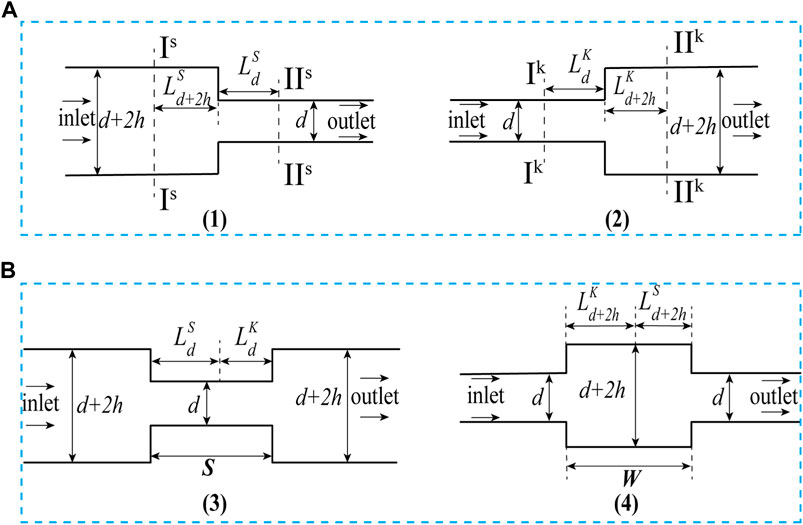
FIGURE 3. Schematic diagram of Single-Type and Comprehensive-Type structure. (A) Single-Type structure, (B) Comprehensive-Type structure.
In Figure 3, d is the small diameter(m); .The pressure decrease in the shrinking structure results in effective flow passage lengths of
The pressure drop calculation formula is as follows for the shrinkage and expansion structure (Dalal and Pandit, 2012; Zhang et al., 2015; Liu et al., 2016) (as depicted in Figure 3A):
In these formulas:
The pressure drop calculation formula is as follows for the shrinkage–expansion and expansion–shrinkage structure (Liu et al., 2016; Yao et al., 2019) (as depicted in Figure 3B):
In these formulations,
In these formulations,
In these formulas:
2.3 Calculating the pressure drop for BBHE
The structure of BBHE can be expressed as shown in Figure 4. The pressure drop superposition can extend the formula for BBHE’s pressure drop computation.
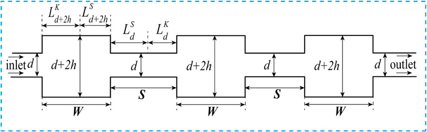
FIGURE 4. Schematic diagram of BBHE structure.
In this formula:
2.4 Structural parameter optimization
2.4.1 Basic structure parameters
In contrast to CBHE, BBHE has the circular groove installed on the inside wall. According to Table 1, a circular groove’s precise measurements are its depth, width, and slot pitch.

TABLE 1. Parameters of the BBHE’s structure.
2.4.2 Functions of the objective and constraint
To make it easier to study BBHE’s properties for drag reduction. As shown in Figure 5, two circular groove elements were selected to further simplify the BBHE pressure drop formula and obtain the objective function.
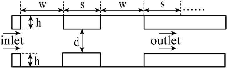
FIGURE 5. BBHE schematic diagram.
In this formula:
The objective function used to optimize the structural parameters of BBHE is as follows:
The constraint function for BBHE structural parameter optimization can be obtained as follows when combined with the pressure drop constraint conditions:
In these formulas: d is diameter (m); w is groove width (m); s is slot pitch (m); h is groove depth (m);
2.4.3 Optimization process
A genetic algorithm (GA) is an optimization algorithm inspired by natural selection and uses the concept of survival of the fittest (Mayer et al., 2020). Through mathematics and computer simulation, the algorithm transforms the process of solving the problem into a process similar to the crossover and mutation of chromosome genes in biological evolution (Farmakis, 2018; Jalali et al., 2020). Chromosome representation, selection, crossover, mutation and fitness function calculation are the critical steps of genetic algorithms (Katoch et al., 2021). When solving complex combinatorial optimization problems, better optimization results can be obtained faster than some conventional optimization algorithms.
Figure 6 shows the optimization process of the structural parameters of the BBHE. Firstly, the BBHE structural parameter optimization problem was implemented to implement chromosome coding. Then the solving process was transformed into a process similar to the evolution, selection, crossover, and mutation of chromosome genes in biological evolution. In the optimization process, we should always take the minimum pressure drop of the objective function as the optimization target because this can ensure the minimum fluid resistance in the BBHE.
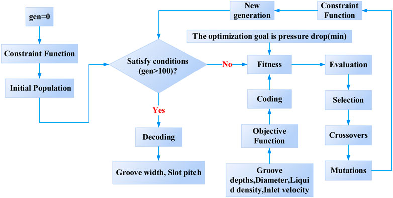
FIGURE 6. BBHE optimization process.
2.4.4 Optimization results
The minimum pressure drop of BBHE is used as the optimization objective under any groove depth parameters after the velocity, diameter, and liquid density at the input of BBHE have been provided.
The objective function and constraint function are solved by a genetic algorithm. As illustrated in Figure 7, the corresponding groove width and slot pitch may then be determined. With different diameter BBHE, groove depths increase, groove width and slot pitch is also present a linear increasing trend.
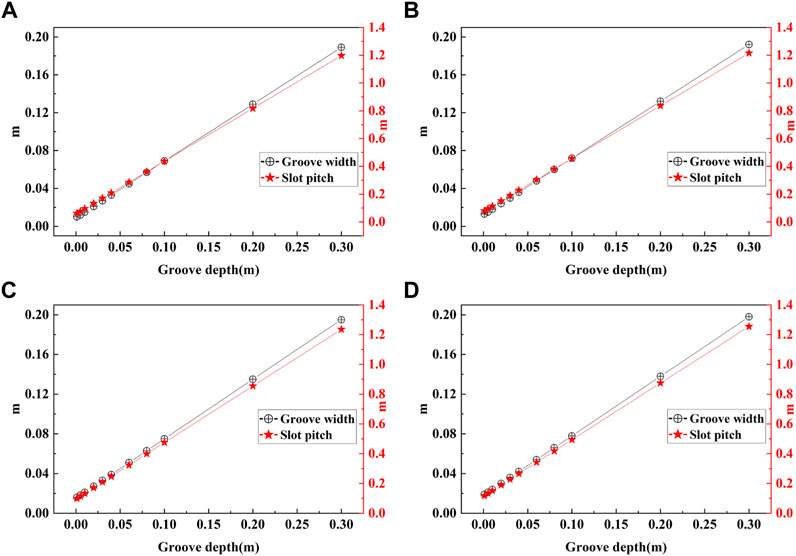
FIGURE 7. Changes in groove width and slot pitch for various groove depths: (A) Diameter is 0.03 m; (B) Diameter is 0.04 m; (C) Diameter is 0.05 m; (D) Diameter is 0.06 m.
3 Case study
3.1 Numerical simulation of BBHE and CBHE
3.1.1 Set basic parameters
COMSOL Multiphysics software was used for simulation in this paper because it has a unique advantage in multi-physical field coupling (Turgay and Yazıcıoğlu, 2018). It has many predefined physical application modes, ranging from fluid flow and heat conduction to structural mechanics, electromagnetic analysis and other physical fields (Sun et al., 2018). The predefined multi-physics field application mode can solve many common physics problems (Narkuniene et al., 2021). At the same time, the user can choose the required physical field and define the relationship between them. Of course, users can also enter their partial differential equations (PDEs) and specify how they relate to other equations or physics (Vajdi et al., 2020).
We selected the turbulence module (
3.1.2 Analysis of simulation results
Based on the results of parameter groove width and groove spacing obtained by solving the objective function and constraint function with a genetic algorithm, the models of BBHE and conventional borehole heat exchanger are established, respectively.
According to Figure 8, the speed on the axis of each BBHE and the CBHE model is extracted based on the results of the CFD numerical simulation, and the average value is then calculated.
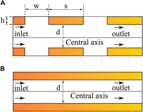
FIGURE 8. Conceptual model: (A) BBHE and (B) CBHE.
In this study, the fluid resistance reduction rate of BBHE can be regarded as the increase of the ratio of the average velocity on the central axis when the fluid flows through BBHE and CBHE under the same numerical simulation conditions. Therefore, the following formula can be used to calculate:
In this formula:
Figure 9 further demonstrates that when the rate of fluid resistance decrease is more significant than zero, the fluid’s resistance in the inner wall of the BBHE is less than that of the CBHE. When the rate of fluid resistance decrease is less than zero, the resistance of the fluid in the inner wall of the BBHE is higher than that of the CBHE.
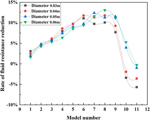
FIGURE 9. The fluid resistance reduction rate of BBHE.
The structural parameters of BBHE play a decisive role in the rate of fluid resistance reduction. Different combinations of structural parameters can produce drag increase or drag reduction effects. It is further explained that when the fluid flows through the circular groove inside the BBHE, the circular groove strongly influences the fluid’s kinematic and dynamic characteristics. This effect is not necessarily to reduce the resistance of fluid flow but to increase the resistance of fluid flow.
3.2 Analysis of the effect
3.2.1 Velocity variation
Figure 10 is the velocity vector diagram of a BBHE model based on CFD numerical simulation. Each circular groove in Figure 10 has a swirl that runs counterclockwise to the pipe’s internal flow.
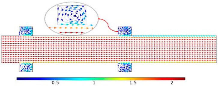
FIGURE 10. The velocity vector of a BBHE.
To further study the characteristics of rotary vortex in circular grooves, four models with the most significant fluid resistance reduction rate of the BBHE model are selected, as shown in Table 2.
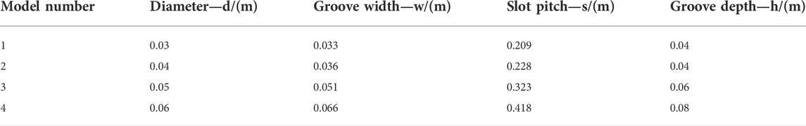
TABLE 2. Four peak rate of fluid resistance reduction models.
Figure 11A shows the dividing line scheme of the four BBHE peak rate fluid resistance reduction models. Line-1 is the leftmost end of the groove width, line-2 is the middle line of the groove width, line-3 is the rightmost end of the groove width, and line-4 is the middle line of the first slot pitch. Figure 11B shows the dividing line schemes of four CBHE, where line-01 corresponds to line-1, line-02 corresponds to line-2, line-03 corresponds to line-3, and line-04 corresponds to line-4.
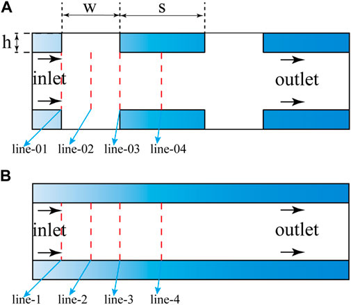
FIGURE 11. Line plan one:(A) BBHE, (B) CBHE.
As shown in Figure 12, the velocity distribution curves perpendicular to different positions of the axis are shown. Figures 12A–D correspond to the velocity variation curves of models 1, 2, 3, and 4, respectively.
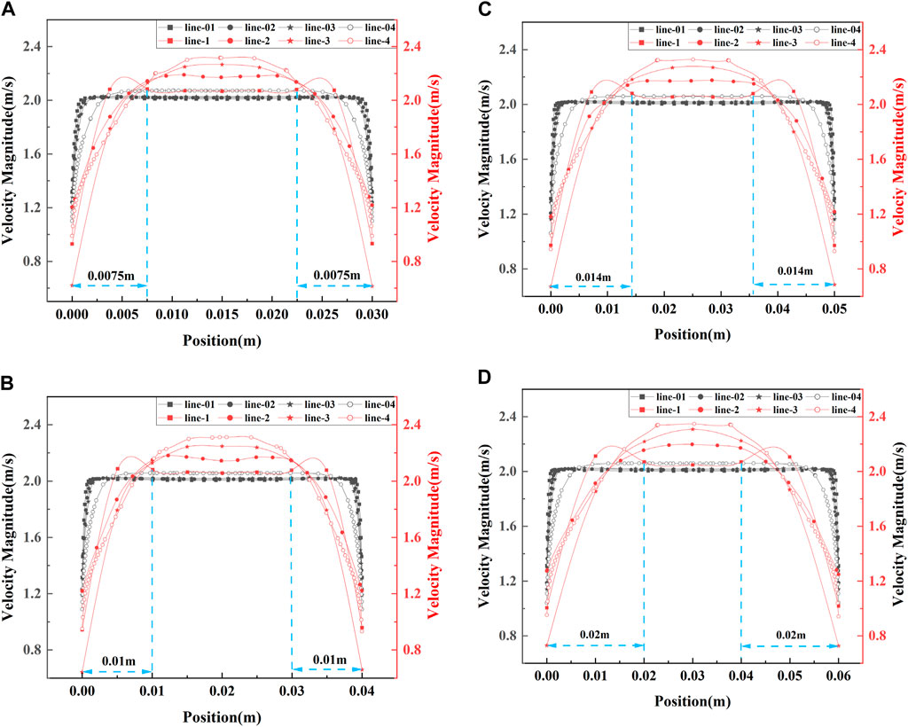
FIGURE 12. Velocity distribution along lines in the line plan: (A) model 1, (B) model 2, (C) model 3, (D) model 4.
Figure 12A shows that the fluid velocity in BBHE is higher than that in CBHE at the region 0.0075 m distant from the wall. Figure 12B shows that the fluid velocity in BBHE is higher than that in CBHE in the area that is 0.01 m distant from the wall. Figure12C shows that the fluid velocity in BBHE is higher than that in CBHE in the area that is 0.014 m from the wall. Figure12D shows that the fluid velocity in BBHE is higher than that in CBHE in the area 0.02 m distant from the wall.
Compared with the CBHE, the BBHE improves the fluid velocity, and the boundary layer effect is more pronounced. The main reasons for the change of boundary layer state are the addition of bionic circular grooves and the reverse vortex generated in the grooves.
3.2.2 Temperature variation
Figure 13A shows the dividing line scheme of the four BBHE peak rate fluid resistance reduction models. Line-1 is the leftmost end of the groove width, line-2 is the middle line of the groove width, line-3 is the rightmost end of the groove width, line-4 is the middle line of the first slot pitch, and line-5 is the middle line of the second slot pitch. Figure 13B shows the dividing line schemes of four CBHE, where line-01 corresponds to line-1, line-02 corresponds to line-2, line-03 corresponds to line-3, line-04 corresponds to line-4, and line-05 corresponds to line 5.
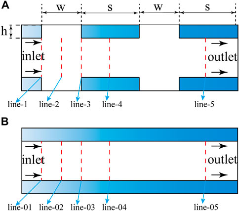
FIGURE 13. Line plan two:(A) BBHE, (B) CBHE.
The high-temperature fluid flows from line01/line1 to line05/line5 and finally reaches a steady state. They are comparing the temperature difference between line05 of the CBHE and the line5 of the BBHE. As shown in Figure 14, the temperature difference is more significant, and the results are more prominent.
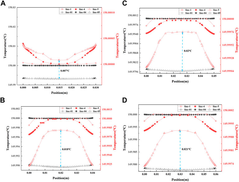
FIGURE 14. Temperature distribution along lines in the line plan: (A) model 1, (B) model 2, (C) model 3, (D) model 4.
Assuming the inlet temperature is 150°C, the initial temperature of the water is 20°C. As shown in Figure Figure14, the temperature distribution curves are perpendicular to different axes’ positions. (A), (B), (C), and (D) correspond to the temperature variation curves of models 1, 2, 3, and 4, respectively.
Figure 14A shows that the temperature difference between line-5 in BBHE and line-05 in CBHE is 0.007°C. Figure 14B shows that the temperature difference between line-5 in BBHE and line-05 in CBHE is 0.018°C. Figure 14C shows that the temperature difference between line-5 in BBHE and line-05in CBHE is 0.02°C. Figure 14D shows that the temperature difference between line-5 in BBHE and line-05 in CBHE is 0.021°C.
It can be seen from Figure 14 that compared with the temperature on line-05 and line-5, it is evident that the temperature transmission rate of the BBHE is faster. The increased fluid velocity in the BBHE can increase the temperature transmission rate. Compared with CBHE, the thermal boundary layer effect of BBHEs is more prominent. The addition of bionic circular grooves and the reverse vortex generated inside are the main reasons for the increase in temperature transmission rate.
4 Conclusion
(1) Compared with the CBHE, the BBHE improves the fluid velocity, and the boundary layer effect is more pronounced. The main reasons for the change of boundary layer state are the addition of bionic circular grooves and the reverse vortex generated in the grooves. Under the same numerical simulation conditions, the fluid resistance reduction rate of the BBHE can reach 13%.
(2) Under the same numerical simulation conditions, CFD numerical simulation results show that increased fluid velocity in BBHE can promote the temperature transfer rate. The addition of bionic circular grooves and the reverse vortex generated inside are the main reasons for the increase in temperature transmission rate.
(3) The ideal structural parameters of the BBHE are determined via genetic algorithm optimization analysis and CFD numerical simulation, and they are as follows: diameter is 60 mm, 66 mm for the groove width, 418 mm for the slot pitch, and 80 mm for the groove depth.
Future work is planned to build an extensive and complete geothermal system, including BBHE and use a high-performance computer to complete the simulation. At the same time, a geothermal system test bench containing BBHE was set up for the experiment.
Data availability statement
The original contributions presented in the study are included in the article/supplementary material, further inquiries can be directed to the corresponding author.
Author contributions
Conceptualization, JZ and YL; Methodology, JZ; Software, JZ and ZD; Formal analysis, JZ, YL, and XQ; Writing—original draft preparation, JZ; Writing—review and editing, QM and XX; Funding acquisition, YL, XQ, and JL; Visualization, JZ, YL, and JL; All authors read and agreed to the published version of the manuscript.
Funding
The authors gratefully acknowledge the financial support from the Natural Science Foundation of China (No. 42002307), Fundamental Research Funds for the Central Universities, China (No. 2652019070), and the National Key Research and Development Program of China (No.2018YFC0603405, 2021YFA0719100).
Acknowledgments
The authors would like to thank the editor and the reviewers for their helpful comments.
Conflict of interest
The authors declare that the research was conducted in the absence of any commercial or financial relationships that could be construed as a potential conflict of interest.
Publisher’s note
All claims expressed in this article are solely those of the authors and do not necessarily represent those of their affiliated organizations, or those of the publisher, the editors and the reviewers. Any product that may be evaluated in this article, or claim that may be made by its manufacturer, is not guaranteed or endorsed by the publisher.
References
Aghahosseini, A., and Breyer, C. (2020). From hot rock to useful energy: A global estimate of enhanced geothermal systems potential. Appl. Energy 279, 115769–115788. doi:10.1016/j.apenergy.2020.115769
Alimonti, C., Soldo, E., Bocchetti, D., and Berardi, D. (2018). The wellbore heat exchangers: A technical review. Renew. Energy 123, 353–381. doi:10.1016/j.renene.2018.02.055
Asidin, M., Suali, E., Jusnukin, T., and Lahin, F. (2019). Review on the applications and developments of drag reducing polymer in turbulent pipe flow. Chin. J. Chem. Eng. 27 (8), 1921–1932. doi:10.1016/j.cjche.2019.03.003
Bacher, E. V., and Smith, C. R. (1985). “A combined visualization-anemometry study of the turbulent drag reducing mechanisms of triangular micro-groove surface modifications,” in Shear Flow Control Conference, Boulder,CO,U.S.A., 12 March 1985 - 14 March 1985.
Bouhacina, B., Saim, R., and Oztop, H. F. (2015). Numerical investigation of a novel tube design for the geothermal borehole heat exchanger. Appl. Therm. Eng. 79, 153–162. doi:10.1016/j.applthermaleng.2015.01.027
Chai, Y., Li, X., Geng, J., Pan, J., Huang, Y., and Jing, D. (2019). Mechanistic study of drag reduction in turbulent pipeline flow over anionic polymer and surfactant mixtures. Colloid Polym. Sci. 297 (7), 1025–1035. doi:10.1007/s00396-019-04525-2
Chen, I. Y., Wongwises, S., Yang, B.-C., and Wang, C.-C. (2010). Two-phase flow across small sudden expansions and contractions. Heat. Transf. Eng. 31 (4), 298–309. doi:10.1080/01457630903312056
Choi, K.-S. (1989). Near-wall structure of a turbulent boundary layer with riblets. J. Fluid Mech. 208 (-1), 417–458. doi:10.1017/s0022112089002892
Cui, G., Ren, S., Zhang, L., Ezekiel, J., Enechukwu, C., Wang, Y., et al. (2017). Geothermal exploitation from hot dry rocks via recycling heat transmission fluid in a horizontal well. Energy 128, 366–377. doi:10.1016/j.energy.2017.04.027
Cya, C., Ss, B., Kai, L. C., Ssd, E., Rharc, F., and Jrvo, D. (2020). Nature–Inspired self–cleaning surfaces: Mechanisms, modelling, and manufacturing. Chem. Eng. Res. Des. 155, 48–65. doi:10.1016/j.cherd.2019.11.038
Dalal, D. C., and Pandit, S. K. (2012). Transient solution of an incompressible viscous flow in a channel with sudden expansion/contraction. Int. J. Mech. Mechatronics Eng. 6 (7), 1158–1169. doi:10.5281/zenodo.1332650
Daneshipour, M., and Rafee, R. (2017). Nanofluids as the circuit fluids of the geothermal borehole heat exchangers. Int. Commun. Heat Mass Transf. 81, 34–41. doi:10.1016/j.icheatmasstransfer.2016.12.002
Dean, B., and Bhushan, B. (2010). Shark-skin surfaces for fluid-drag reduction in turbulent flow: A review. Phil. Trans. R. Soc. A 368, 5737–4806. doi:10.1098/rsta.2010.0294
Dos Santos, D. D. O., Frey, S. L., Naccache, M. F., and de Souza Mendes, P. R. (2014). Flow of elasto-viscoplastic liquids through a planar expansion–contraction. Rheol. Acta 53 (1), 31–41. doi:10.1007/s00397-013-0736-0
Farmakis, P. M., and Chassiakos, A. P. (2018). Genetic algorithm optimization for dynamic construction site layout planning. Organ. Technol. Manag. Constr. Int. J. 10 (1), 1655–1664. doi:10.1515/otmcj-2016-0026
Gharibi, S., Mortezazadeh, E., Hashemi Aghcheh Bodi, S. J., and Vatani, A. (2018). Feasibility study of geothermal heat extraction from abandoned oil wells using a U-tube heat exchanger. Energy 153, 554–567. doi:10.1016/j.energy.2018.04.003
He, Y., and Bu, X. (2020). A novel enhanced deep borehole heat exchanger for building heating. Appl. Therm. Eng. 178, 115643–115649. doi:10.1016/j.applthermaleng.2020.115643
Hermany, L., dos Santos, D. D. O., Frey, S., Naccache, M. F., and de Souza Mendes, P. R. (2013). Flow of yield-stress liquids through an axisymmetric abrupt expansion-contraction. J. Newt. Fluid Mech. 201, 1–9. doi:10.1016/j.jnnfm.2013.07.002
Ibrahim, M., and Hashim, W. (1994). Oscillating flow in channels with a sudden change in cross section. Comput. Fluids 23 (1), 211–224. doi:10.1016/0045-7930(94)90035-3
Iry, S., and Rafee, R. (2019). Transient numerical simulation of the coaxial borehole heat exchanger with the different diameters ratio. Geothermics 77, 158–165. doi:10.1016/j.geothermics.2018.09.009
Jalali, Z., Noorzai, E., and Heidari, S. (2020). Design and optimization of form and facade of an office building using the genetic algorithm. Sci. Technol. Built Environ. 26 (2), 128–140. doi:10.1080/23744731.2019.1624095
Jurasz, J., Canales, F., Kies, A., Guezgouz, M., and Beluco, A. (2020). A review on the complementarity of renewable energy sources: Concept, metrics, application and future research directions. Sol. Energy 195, 703–724. doi:10.1016/j.solener.2019.11.087
Katoch, S., Chauhan, S. S., and Kumar, V. (2021). A review on genetic algorithm: Past, present, and future. Multimed. Tools Appl. 80 (5), 8091–8126. doi:10.1007/s11042-020-10139-6
Lim, H., Kim, C., Cho, Y., and Kim, M. (2017). Energy saving potentials from the application of heat pipes on geothermal heat pump system. Appl. Therm. Eng. 126, 1191–1198. doi:10.1016/j.applthermaleng.2017.04.086
Liu, C., Sheng, C., Yang, H., and Yuan, Z. (2018). Design and optimization of bionic janus blade in hydraulic torque converter for drag reduction. J. Bionic Eng. 15 (1), 160–172. doi:10.1007/s42235-017-0013-5
Liu, J., Yao, L., Zhang, Y., and Chen, J. (2016). The calculation method of local pressure drop on variable cross-section circular tube structure. Mach. Des. Manuf. 5 (5), 83–87. doi:10.19356/j.cnki.1001-3997.2016.05.022
Liu, W., Ni, H., Wang, P., and Zhou, Y. (2020). An investigation on the drag reduction performance of bioinspired pipeline surfaces with transverse microgrooves. Beilstein J. Nanotechnol. 11 (1), 24–40. doi:10.3762/bjnano.11.3
Mayer, M. J., Szilágyi, A., and Gróf, G. (2020). Environmental and economic multi-objective optimization of a household level hybrid renewable energy system by genetic algorithm. Appl. Energy 269, 115058–115074. doi:10.1016/j.apenergy.2020.115058
Moayedi, H., Aghel, B., Vaferi, B., Foong, L. K., and Bui, D. T. (2020). The feasibility of Levenberg–Marquardt algorithm combined with imperialist competitive computational method predicting drag reduction in crude oil pipelines. J. Pet. Sci. Eng. 185, 106634–106651. doi:10.1016/j.petrol.2019.106634
Narkuniene, A., Poskas, P., and Justinavicius, D. (2021). The modeling of laboratory experiments with COMSOL Multiphysics using simplified hydromechanical model. Minerals 11 (7), 754–772. doi:10.3390/min11070754
Nian, Y.-L., and Cheng, W.-L. (2018). Evaluation of geothermal heating from abandoned oil wells. Energy 142, 592–607. doi:10.1016/j.energy.2017.10.062
Song, X., Shi, Y., Li, G., Yang, R., Wang, G., Zheng, R., et al. (2018). Numerical simulation of heat extraction performance in enhanced geothermal system with multilateral wells. Appl. Energy 218, 325–337. doi:10.1016/j.apenergy.2018.02.172
Sun, J., and Bhushan, B. (2018). Nanomanufacturing of bioinspired surfaces. Tribol. Int. 129, 67–74. doi:10.1016/j.triboint.2018.08.007
Sun, X., Luo, H., and Soga, K. (2018). A coupled thermal–hydraulic–mechanical–chemical (THMC) model for methane hydrate bearing sediments using COMSOL Multiphysics. J. Zhejiang Univ. Sci. A 19 (8), 600–623. doi:10.1631/jzus.a1700464
Turgay, M. B., and Yazıcıoğlu, A. G. (2018). Numerical simulation of fluid flow and heat transfer in a trapezoidal microchannel with COMSOL multiphysics: A case study. Numer. Heat. Transf. Part A Appl. 73 (5), 332–346. doi:10.1080/10407782.2017.1420302
Vajdi, M., Moghanlou, F. S., Sharifianjazi, F., Asl, M. S., and Shokouhimehr, M. (2020). A review on the Comsol Multiphysics studies of heat transfer in advanced ceramics. jcc. 2 (2), 35–44. doi:10.29252/jcc.2.1.5
Vakulchuk, R., Overland, I., and Scholten, D. (2020). Renewable energy and geopolitics: A review. Renew. Sustain. Energy Rev. 122, 109547–109559. doi:10.1016/j.rser.2019.109547
van der Zwaan, B., and Dalla Longa, F. (2019). Integrated assessment projections for global geothermal energy use. Geothermics 82, 203–211. doi:10.1016/j.geothermics.2019.06.008
Walsh, M. J. (1982). “Turbulent boundary layer drag reduction using riblets,” in AIAA, Aerospace Sciences Meeting, Orlando,FL,U.S.A., 11 January 1982 - 14 January 1982, 169–178.
Wilkinson, S. P., Anders, J. B., Lazos, B. S., and Bushnell, D. M. (1988). Turbulent drag reduction research at nasa langley - progress and plans. Int. J. Heat Fluid Flow 9 (3), 266–277. doi:10.1016/0142-727x(88)90037-9
Yao, L., Liu, J., Li, X., Yue, Q., Liu, Y., and Wang, H. (2019). Application of the building block approach to characterize the pressure loss of water and fracturing fluid in contraction-expansion pipe. J. Pet. Sci. Eng. 176, 51–61. doi:10.1016/j.petrol.2018.12.010
Yu, C., Liu, M., Zhang, C., Yan, H., Zhang, M., Wu, Q., et al. (2020). Bio-inspired drag reduction: From nature organisms to artificial functional surfaces. Giant 2, 100017–100029. doi:10.1016/j.giant.2020.100017
Yuan, Y., Jing, J., Yin, R., Jing, P., and Hu, J. (2022). Experimental research on cationic surfactants in the drag reduction of water injection pipeline. SPE Prod. Operations 37 (02), 331–345. doi:10.2118/209593-pa
Zabihi, R., Mowla, D., and Karami, H. R. (2019). Artificial intelligence approach to predict drag reduction in crude oil pipelines. J. Pet. Sci. Eng. 178, 586–593. doi:10.1016/j.petrol.2019.03.042
Zhang, Z., Lin, C., Ye, W., Wei, A., Xiao, L., and Ai, W. (2015). Research on the flow characteristics of sudden-reduction oil tube. Open Mech. Eng. J. 9 (1), 77–79. doi:10.2174/1874155x01509010077
Keywords: geothermal energy, bionic non-smooth surface, bionic borehole heat exchanger, genetic algorithm, CFD
Citation: Zhang J, Liu Y, Qin X, Dou Z, Meng Q, Xu X and Lv J (2022) Optimization design and drag reduction characteristics of bionic borehole heat exchanger. Front. Energy Res. 10:1024623. doi: 10.3389/fenrg.2022.1024623
Received: 22 August 2022; Accepted: 12 September 2022;
Published: 28 September 2022.
Edited by:
Changhui Liu, China University of Mining and Technology, ChinaReviewed by:
Qiang Liu, China University of Petroleum, Beijing, ChinaHaichao Zhou, Jiangsu University, China
Copyright © 2022 Zhang, Liu, Qin, Dou, Meng, Xu and Lv. This is an open-access article distributed under the terms of the Creative Commons Attribution License (CC BY). The use, distribution or reproduction in other forums is permitted, provided the original author(s) and the copyright owner(s) are credited and that the original publication in this journal is cited, in accordance with accepted academic practice. No use, distribution or reproduction is permitted which does not comply with these terms.
*Correspondence: Yongsheng Liu, eW9uZ3NoZW5nQGN1Z2IuZWR1LmNu