 Yan Xia1,2
 Zetao Feng
94% of researchers rate our articles as excellent or good
Learn more about the work of our research integrity team to safeguard the quality of each article we publish.
Find out more
METHODS article
Front. Energy Res., 20 September 2022
Sec. Smart Grids
Volume 10 - 2022 | https://doi.org/10.3389/fenrg.2022.1020676
This article is part of the Research TopicFuture Electricity System Based on Energy Internet: Energy storage system design, Optimal Scheduling, Security, Attack Model and CountermeasuresView all 14 articles
Grid-connected inverters need to reduce current harmonics as much as possible. After introducing the input signal’s fundamental and main harmonic quadrature components, a discrete state model is created, and the discrete observer design method is used to propose a harmonic extraction algorithm called quadrature sinewave extractor (QSE). The QSE is a stable recursive operator with the advantages of no phase displacement and the ability to eliminate mutual influence between harmonic components. Compared to the widely used proportional multi-resonant controller, QSE can reduce current harmonics and improve system stable performance by using it in the current control of grid-connected inverters. Finally, comparative experiments on a three-phase grid-connected inverter are used to verify the proposed method’s effectiveness.
The exhaustion and pollution of traditional fossil energy promote the development and utilization of renewable energy such as solar and wind energy, and the proportion of new energy power generation in the power system increases greatly. The grid-connected inverter converts DC energy into AC energy, and its performance directly affects the power grid. One key indicator of new energy power quality is the inverter output current harmonics. The requirements for outputting current harmonic content are clearly stated in IEEE 1547–2003 and other specifications, so lowering the harmonic content is critical (Lee and Cho, 2020).
A variety of factors can cause the output current harmonics of the inverter. The modulation dead time of the inverter’s upper and lower bridge arms, the voltage drop of power switching devices, the grid voltage distortion, the fluctuation of DC power supply, the voltage fluctuation of the DC bus capacitor, and the nonlinearity of the system transformer or reactor are the main causes of inverter output current harmonics. The harmonic suppression method studied in this paper is to detect the harmonic in the current and realize harmonic suppression through closed-loop feedback. Therefore, this paper aims at the harmonic generated by any of the above reasons.
The LCL filter can filter out the output current’s high-frequency harmonics, and the current closed-loop controller is primarily responsible for suppressing the low-frequency current harmonics (Chen et al., 2013; Yang et al., 2015). The current closed-loop controller is an important factor affecting output current harmonics’ performance (Cárdenas et al., 2012; Tuan and Santoso, 2016). There are many effective current closed-loop control algorithms for suppressing current harmonics, and the main difference between them is the harmonic extraction method (Castilla et al., 2013; Kulkarni and John, 2013; Zhao et al., 2013; Bourguiba et al., 2016; Wang et al., 2016; Qian et al., 2017; Zhaoyang et al., 2017; Busarello et al., 2018; Hu et al., 2018; McDonald and Li, 2018; Chen et al., 2019; Choi and Sarlioglu, 2019; Fei et al., 2019; Song et al., 2020).
The repetitive controller (RC) is derived from the internal model control principle (Busarello et al., 2018; McDonald and Li, 2018), which takes advantage of harmonics’ periodic characteristics. A positive feedback loop with periodic delay is chosen as the internal model, assuming that the harmonic signal repeatedly occurs in each fundamental cycle. As long as the input signal contains a harmonic signal that is an integral multiple of the fundamental frequency, the internal model’s output can continuously accumulate the harmonic signal and suppress the harmonic by multiplying the output harmonic signal with a certain coefficient as the control voltage. The advantage of RC is that all harmonics can be extracted with simple delayed positive feedback. In comparison, the main disadvantage of RC is that it has a resonance effect on all harmonics, rather than focusing on suppressing some major harmonics. In addition, RC needs to save the period data of the fundamental wave, which cannot extract non-integer harmonics. So the control frequency of RC is required to be an integral multiple of the fundamental frequency, and it is not suitable for frequency variation. These shortcomings limit its application in practice (McDonald and Li, 2018).
Proportional multi-resonance control uses multiple quasi-resonance controllers (MQR) to suppress some major low-order harmonics (Castilla et al., 2013; Bourguiba et al., 2016; Wang et al., 2016; Qian et al., 2017; Zhaoyang et al., 2017; Hu et al., 2018; Choi and Sarlioglu, 2019; Song et al., 2020). It takes advantage of the fact that the amplitudes of some lower harmonics, especially odd harmonics, are usually larger than that of the higher harmonics (Qian et al., 2017). A resonant controller is used as its internal mode for harmonic extraction and suppression of the main harmonics to be suppressed. In practice, a quasi-resonant controller is generally formed by adding appropriate damping to the system to deal with a slight deviation of the fundamental frequency. Introducing a resonance controller can significantly improve the open-loop gain of the transfer function at the dominant harmonics frequency and reduces the harmonic content. However, the defect of resonant controller is that while extracting the desired frequency harmonics, it will also pass through other harmonics. The phase shift of other harmonics will increase the amplitude of corresponding harmonics and even make the system diverge (Zhao et al., 2013).
There are also some intelligent harmonic extraction methods, such as least mean square filter (Kulkarni and John, 2013), adaptive neural network filter (Fei et al., 2019), and discrete Fourier transform based on extended Kalman filter (Chen et al., 2019). However, their design process is complex, and the calculation time is long, so they are not widely used. The most widely harmonic suppression algorithms used are proportional multi resonance and repetitive control at present.
In view of the shortcomings of MQR in extracting harmonics (Kulkarni and John, 2013), this paper designs a new discrete harmonic extractor called quadrature sine wave extractor (QSE), which uses the idea of the observer (Quan et al., 2016; Wang, 2016) to extract multiple harmonic components at the same time, which is an improvement of MQR. QSE will not cause the phase shift of the frequency component to be extracted, which avoids the phase shift problem caused by the discretization of controller design in the traditional continuous domain. QSE extracts each frequency component simultaneously, avoiding the coupling problem caused by the traditional MQR to extract each frequency component separately. Experiments show that the high-performance harmonic extraction method is conducive to reducing output current harmonics of the grid-connected inverter.
According to the Fourier decomposition theory, the periodic signal can be decomposed into a linear combination of multiple cosine waves:
Where, u is the input signal; n is the nth sampling time; uck (n) = Mkcos (nkωT + δk). uck (n) is the kth cosine wave. When k is zero, uck (n) is the DC component; when k is 1, it is the fundamental wave; when k is greater than 1, it is the kth harmonic. In this paper, uck (n) is collectively referred to as the kth cosine wave. Mk is the kth cosine wave amplitude; δk is the initial phase of the kth cosine wave; T is the sampling time interval; ω is the fundamental angular frequency; Θ is the value set of k. Considering the main low-order harmonics of the actual three-phase grid-connected inverter are 5 and 7 times in practice (Bourguiba et al., 2016), and it is also necessary to control the fundamental wave, the Θ of QSE is set as {1,5,7}.
In order to establish the mathematical model, the sinusoidal signal delaying one-quarter of the period of each cosine wave is introduced. That is usk (n) = Mksin (nkωT+δk), uck, and usk form a set of orthogonal sine waves called cosine and sine wave, respectively. Taking the amplitude and initial phase of the orthogonal sine wave as constants, the state equations of uck and usk can be expressed:
Where,
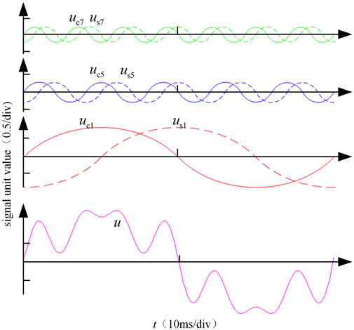
FIGURE 1. Typical periodic signal.
The cosine wave in Figure 1 includes fundamental wave uc1, fifth harmonic uc5 and seventh harmonic uc7, that is u = uc1+ uc5+ uc7. The dotted lines in Figure 1 are sine waves, namely us1, us5 and us7.
The basic idea of QSE is to inversely deduce each orthogonal sine wave according to the sampled signal based on state Eq. 2 and output Eq. 1. Considering the variables uck and usk as the state of the system and u as the measured value of the system, then the harmonic extraction problem is transformed into a typical state observer design problem. Based on this idea, the QSE proposed in this paper is designed as a discrete closed-loop block diagram, as shown in Figure 2.
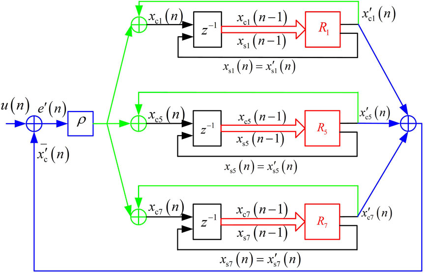
FIGURE 2. Block diagram of QSE.
Figure 2 shows the unit negative feedback structure. If the number of elements in the set Θ is N, the forward channel contains N oscillators in parallel. QSE design includes three steps: prediction, calculation of prediction error, and correction.
The first step is prediction, as shown in the red part of Figure 2. According to the prediction of model Eq. 2, the prediction formula of the kth orthogonal sine wave is:
Where, xck (n-1) and xsk (n-1) are the estimated value of the kth orthogonal sine wave at the last time, and the initial value of its iteration can be taken as zero, which is reflected in the output of the z−1 module in Figure 1 x′ck(n) and x′sk(n) are the predicted value of the kth orthogonal sine wave at the current time.
The second step is calculating the prediction error, as shown in the blue part of Figure 2. The calculation equation of prediction error is:
Where e′(n) is the prediction error, x′c (n) = ∑k∈Θx′ck(n) is the total prediction.
The third step is correction, as shown in the green part in Figure 2. The correction formula of the kth orthogonal sine wave is:
Where xck (n) and xsk(n) are the current extraction results of the orthogonal sine wave, ρ is the update coefficient. The total estimated value after correction is xc(n) = ∑k∈Θxck(n). In each sampling period, (Eqs. 3–5) form QSE in turn.
Property 1. When the update coefficient ρ meets 0< ρ < 2 / N, QSE is convergent.
Property 2. The k times fundamental frequency components contained in xck and xsk of QSE steady-state output are equal to uck and usk respectively, and there is no phase offset and amplitude change between xck/xsk and uck/usk.
Property 3. xck and xsk of QSE steady-state output do not contain any other components in sets Θ except k times fundamental frequency components.The above three properties are called the stability, zero-error and decoupling of QSE, respectively. The process of proving the three properties is shown in Appendix A.The discrete transfer function of the kth oscillator can be obtained from (Eqs. 3–5):
Substituting z = ejkωT into Eq. 6 at frequency kω, the following equation can be written:
Eq. 7 shows that the open-loop gain of the system is infinite, so the steady-state error of that is zero. Therefore, the oscillator has the effect of resonance to the kth cosine wave or sine wave. Since QSE is stable, there must be no kth cosine or sine wave in the steady-state error. Otherwise, the oscillator’s output will become larger, eventually leading to QSE output divergence. The zero-error property of QSE is further explained based on the above discussions.Further, the transfer function of QSE can be deduced as follow
According to the transformation relationship between the s-domain and z-domain transfer function, the continuous domain observer of QSE is shown in Figure 3.If there is only one oscillator in the forward channel in the QSE, the QSE degenerates into a band-pass filter, that is, a quasi-resonant controller. The continuous transfer function of the kth band-pass filter is:
Where, B is the filter bandwidth, and its relationship with the update coefficient ρ of QSE is BT = ρ. This formula establishes the relationship between the update coefficient and filter bandwidth, and provides a reference for selecting the update coefficient ρ.MQR uses multiple band-pass filters to extract harmonics, respectively. The output of each band-pass filter must contain other extracted harmonics. For example, the output of the fundamental band pass filter not only contains certain fifth and seventh harmonics components, but also has a certain phase shift to the fifth and seventh harmonics. Correspondingly, the output of the fifth or seventh harmonic bandpass filter also contains the fundamental component and has a certain phase shift for the fundamental wave, reflecting the interaction between the components extracted with MQR.The input signal shown in Figure 1 is extracted and simulated by QSE and MQR. Their output comparison results are shown in Figure 4.In Figure 4, the initial value of each orthogonal sine wave is taken as zero, the update coefficient as 0.05, and the sampling period as 100 µs? The number that one fundamental cycle can be updated is 20 m/100 µs= 200. Figure 4A shows the QSE extraction results, it can be seen that in less than half a fundamental cycle, each output sine wave basically coincides with each component of the input signal, and the total output xc (sum of cosine waves) also coincides with the input signal, achieving an ideal extraction effect. The extraction effect of MQR on each component of the input signal under the same parameters and initialization conditions as QSE is shown in Figure 4B. It can be seen that in the steady state, the total output and input signals cannot coincide. The comparison in Figure 4 fully reflects the advantage that QSE can eliminate the interaction between the harmonics components to be extracted.
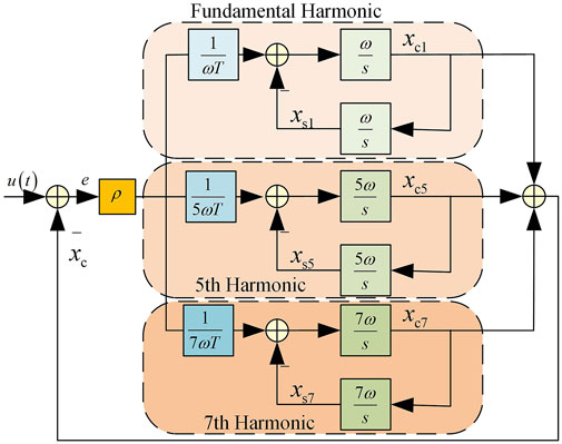
FIGURE 3. Corresponding harmonic observer in continuous domain of QSE.
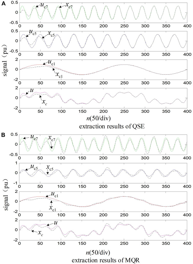
FIGURE 4. Comparation of extraction results of QSE and MQR, “signal” is the signal to be extracted and “n” is the sampling period.
As a harmonic extraction algorithm, QSE has a very wide application prospect. This paper only takes the current loop of a three-phase grid-connected inverter as an example to illustrate the application of QSE in harmonic elimination. The circuit topology of the three-phase grid-connected inverter is shown in Figure 5.
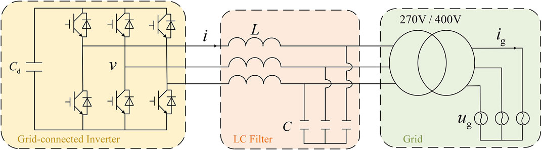
FIGURE 5. Three-phase grid-connected inverter.
In Figure 5, L is the filter inductance of the inverter, C is the AC filter capacitor, and Cd is the DC Bus support capacitor. ug is the grid voltage, v is the output modulation voltage of the inverter, i is the inverter output current, and ig is the grid current.
The three-phase system in Figure 5 has no neutral line, so only the two-phase current can be controlled independently. The coordinate transformation from three-phase (abc) to two-phase (αβ)can reduce the number of control loops. The transformation matrix is:
In the two-phase stationary coordinate system, the current loop based on QSE is shown in Figure 6. The frequency locked loop (FLL) is used to obtain the angular frequency and fundamental positive sequence component of grid voltage. The specific implementation of FLL can refer to references (Zhao et al., 2013) and (Kulkarni and John, 2013). Due to space limitations, this article will not repeat it.
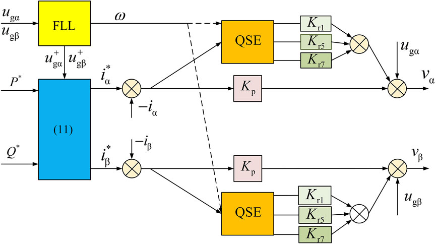
FIGURE 6. Current loop based on QSE.
Eq. 11 in Figure 6 is the given current calculation formula of the current loop, which can be written as:
Where, i∗ α, i∗β are the current given values in the two-phase stationary coordinate system, respectively; p∗, Q∗ are the given values of active power and reactive power to be sent to the power grid, respectively; u + gα and u + gβ are the positive sequence components of the grid voltage in the two-phase stationary coordinate system output by FLL respectively.
The current control based on QSE consists of three parts: current error proportional control, grid voltage feedforward element, and QSE. Proportional control is the basic control that makes the system form negative feedback and closed-loop stability. The feedforward elements ugα and ugβ are to counteract dynamic effects of grid voltage disturbance.
This paper mainly introduces the specific design methods of QSE, which are implemented in the α and β control loop respectively. The input of QSE is the error between the given current and feedback current. Theoretically, QSE should extract the current harmonics of the grid current, that is the current of transformer secondary side. In this paper, considering that the current sensor is installed at the transformer primary side, the inverter output current is selected as the feedback current. The effect of the two current feedback modes is consistent when the grid voltage distortion is small enough to be negligible. On the contrary, if the influence of grid distortion is to be taken into account, QSE needs to extract the harmonic of the grid current.
The output of FLL is the angular frequency ω required for QSE design. If the grid voltage frequency fluctuation is very small, the ω can also be regarded as a constant, which reduces the complexity of the FLL and avoids the real-time trigonometric function operation of QSE. The fundamental, fifth and seventh cosine waves output by QSE are multiplied by the corresponding control coefficients Kr1, Kr5 and Kr7 respectively, and the results are used as one of the control voltages v of the inverter.
The recommended values of the proportional control coefficient and each harmonic control coefficient are: Kp = Lfc, Kr1 = Kr5 = Kr7 = 5Kp, where fc is switching frequency of the inverter power switch devices, which needs to be corrected according to the transfer function of the system. This paper will discuss the selection of these control parameters in combination with specific experimental parameters in the following section.
In order to verify the adaptability of the proposed QSE algorithm to the grid frequency fluctuation, an experimental setup is built up in the laboratory. The main circuit topology of the experimental platform is shown in Figure 5. The inverter rated power is 50kW, the rated voltage (line voltage) is 400 V, and the rated current is 72A. The transformer capacity is 50 kV A, the transformation ratio is 270 V/400 V, the connection method is △/y, and the transformer leakage inductance is about 5% of the rated impedance. This paper adopts the inverter side current feedback control to avoid LCL resonance. The LC filter parameters are shown in Table 1. SVPWM modulation is adopted, and the control platform is based on DSP28335. The switching frequency is 5 kHz. In one SVPWM carrier cycle, current sampling and PWM duty cycle are both updated twice, that is, the control cycle T = 100 µs? The update coefficient ρ of QSE is 0.001, which is equivalent to the filtering bandwidth of 10 rad/s. Using FLL to obtain the angular frequency required by QSE can make it adapt to the frequency change in a larger range. Based on those parameters selected above, the experimental platform and control parameters are listed in Table 1.
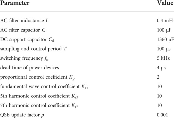
TABLE 1. Parameters of experiments.
Correcting the selected parameters in combination with the system transfer function is necessary. Because of structure consistency between the two control loops α and β, it is only necessary to design the parameters of one loop. For the sake of simplification, the system model only considers the inductance in the design of control parameters, and ignores the influence of filter capacitance and transformer leakage inductance. According to this simplified model, a certain stability margin is reserved in the design, which has lower complexity and facilitates the application in practice. Therefore, the system model can be described as that the modulation voltage v outputted by the inverter acts on the inductor L and generates feedback current after a control period T delay. The discrete transfer function of feedback current and modulation voltage can be obtained as follows:
Where Kr = Kr1 = Kr5 = Kr7.
According to the parameters in Table 1, the open-loop Bode diagram is drawn as the solid line in Figure 7. If the harmonic control coefficient Kr is doubled, the open-loop Bode diagram is shown as the dotted line in the figure. The condition for the stability of the system is that the phases of the phase frequency characteristics on the left of the crossing frequency are above −180 degrees. Comparing the dotted with the solid line, it can be seen that excessive harmonic control coefficient will reduce the stability margin of the system, and the variation of harmonic coefficient within a certain range will increase the amplitude-frequency characteristics at the harmonic frequency without reducing the stability of the whole system. It can also be seen from Bode diagram that if harmonic control is added, the higher the frequency, the lower the phase margin. Therefore, it is not recommended to suppress high-frequency harmonic components.
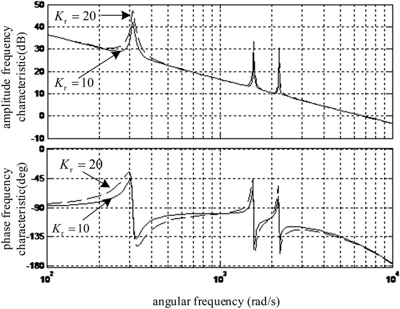
FIGURE 7. The open loop Bode graph of the system.
With an adjustable frequency AC source, experiments are carried out at 50 and 55 Hz, respectively. The QSE-based and MQR-based algorithms are compared when the load ratio is 100 and 30%, and the experimental environment of the two control methods is consistent. The measured waveforms are shown in Figure 8 and Figure 9 iga, igb and igc in the figure are the three-phase grid current, respectively. uga is the voltage on the high-voltage side of the transformer, that is, the grid side. uia is the voltage on the low-voltage side of the transformer, that is, the inverter side.
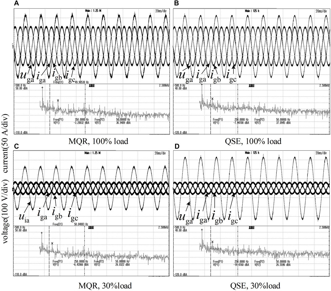
FIGURE 8. Experimental results at 50 Hz
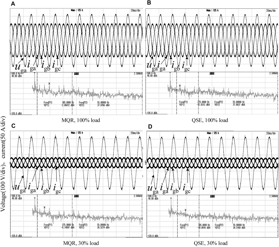
FIGURE 9. Experimental results at 55 Hz
Because the harmonic amplitude is very small compared with the fundamental amplitude, the oscilloscope’s fast Fourier transform (FFT) function is enabled in the experiment, and each waveform shows the FFT result of A phase current. For example, in Figure 8A, the decibel at 350 Hz is −3.288 dB, which means that the amplitude of the seventh harmonic current I7 meets 20l g (I7) = −3.288, that is, the RMS value of I7 is 0.68 A. The decibel of the fundamental current is 36.94 dB, corresponding to 70.3 A. Therefore, it can be calculated that the content of seventh harmonic is 0.97%. The oscilloscope can automatically locate and display the maximum value of each harmonic. According to each current waveform data, oscilloscope record the maximum harmonic value under each working condition, as shown in Table 2, and the recorded total harmonic distortion rate (THD) is shown in Table 3. It can be seen from Table 2 and Table 3 that compared with the MQR, because QSE extracts harmonics more accurately, the control based on QSE can further reduce the harmonic content.

TABLE 2. Maximum of harmonic content.
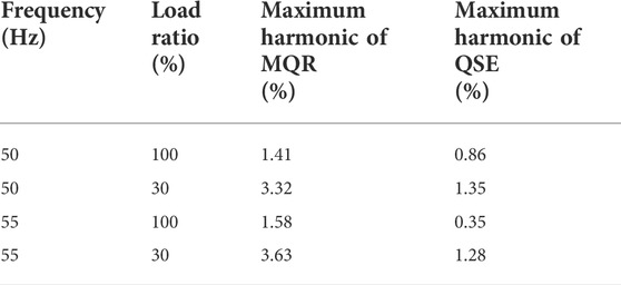
TABLE 3. THD comparison.
According to the above theoretical and experimental results, the following conclusions can be drawn:
1) QSE is designed directly in the discrete domain, avoiding the error caused by the discretization of the continuous domain transfer function so that it can extract the fundamental wave, main harmonic and their orthogonal components without static error.
2) QSE processes all components to be extracted simultaneously. The error used for updating is the difference between the combination of input signal and each component to be extracted, which can eliminate the interaction among those components.
3) QSE can be used in the current control loop of grid-connected inverter, which can greatly reduce current harmonics while maintaining system stability.
In the paper, the study is carried out for steady-state conditions. When considering the grid frequency mutation, we will use the grid simulator to complete the frequency mutation experiments for the QSE. The grid simulator can change frequency, amplitude and other parameters of the grid. Meanwhile, we will conduct QSE extraction experiments under different conditions such as high switching frequency, high-frequency noise and inter-harmonics in the subsequent study.
The original contributions presented in the study are included in the article/Supplementary Material, further inquiries can be directed to the corresponding authors.
YX contributed for analysis of the work and wrote the first draft of the manuscript. ZF is the corresponding author. All authors contributed to manuscript revision, read and approved the submitted version.
This work is partially supported by the Intelligent Electric Power Grid Key Laboratory of Sichuan Province (2022-IEPGKLSP-KFYB05)and Artificial Intelligence Key Laboratory of Sichuan Province (2021RZJ02). The authors also gratefully acknowledge the helpful comments and suggestions of the reviewers, which have improved the presentation.
Author YX and QH were employed by State Grid Sichuan Electric Power Company. Author RC was employed by Zonergy Co., Ltd.
The remaining authors declare that the research was conducted in the absence of any commercial or financial relationships that could be construed as a potential conflict of interest.
All claims expressed in this article are solely those of the authors and do not necessarily represent those of their affiliated organizations, or those of the publisher, the editors and the reviewers. Any product that may be evaluated in this article, or claim that may be made by its manufacturer, is not guaranteed or endorsed by the publisher.
From Eq. A3 ∼ (5), the state equation of QSE is:
Where, both x = [xc1, xs1, xc5, xs5, xc7, xs7, … ]T and b = [1, 0, 1, 0, 1, 0, … ]T is a 2N dimensional column vector. Total state transition matrix
Writing u = [uc1, us1, uc5, us5, uc7, us7, … ]T, the error vector e = u-x, then the recurrence equation of the error vector e(n) can be obtained by combining (Eqs 1, 2, A1):
It can be calculated that when 0<ρ < 2/N:
That is, the module of e(n) is less than or equal to the module of e (n-1) until e(n) converges to the zero vector.
The above derivation proves that when the update coefficient meets 0< ρ < 2/N, QSE is convergent, and the cosine and sine waves of each frequency in the set Θ of input signals are accurately extracted in the steady state, that is, there is no phase offset and amplitude change for each sine wave extraction in the input signal. The above analysis proves the stability and zero-error of QSE.
In the set Θ, since the error e(n) does not contain various harmonics, the output of kth orthogonal sine wave uck and usk does not contain other frequency harmonics except the fundamental frequency component, which proves the decoupling of QSE.
Bourguiba, I., Houari, A., Belloumi, H., and Kourda, F. (2016). “Control of single-phase grid connected photovoltaic inverter,” in Proceeding International Conference on Control Engineering & Information Technology, Hammamet Tunisia, 16-18 December 2016 (IEEE), 1–6. doi:10.1109/CEIT.2016.7929116
Busarello, T. D. C., Pomilio, J. A., and Simoes, M. G. (2018). “Design procedure for a digital proportional-resonant current controller in a grid connected inverter,” in Proceeding IEEE 4th Southern Power Electronics Conference (SPEC), Singapore, 10-13 December 2018 (IEEE), 1–8. doi:10.1109/SPEC.2018.8636052
Cárdenas, R., Juri, C., Peña, R., Wheeler, P., and Clare, J. (2012). The application of resonant controllers to four-leg matrix converters feeding unbalanced or nonlinear loads. IEEE Trans. Power Electron. 27 (3), 1120–1129. doi:10.1109/TPEL.2011.2128889
Castilla, M., Miret, J., Camacho, A., Matas, J., and Vicuna, L. G. d. (2013). Reduction of current harmonic distortion in three-phase grid-connected photovoltaic inverters via resonant current control. IEEE Trans. Ind. Electron. 60 (4), 1464–1472. doi:10.1109/TIE.2011.2167734
Chen, D., Zhang, J., and Qian, Z. (2013). An improved repetitive control scheme for grid-connected inverter with frequency-adaptive capability. IEEE Trans. Ind. Electron. 60 (2), 814–823. doi:10.1109/TIE.2012.2205364
Chen, Z. S., Rhee, S. H., and Liu, G. L. (2019). Empirical mode decomposition based on Fourier transform and band-pass filter. Int. J. Nav. Archit. Ocean Eng. 11 (2), 939–951. doi:10.1016/j.ijnaoe.2019.04.004
Choi, W., and Sarlioglu, B. (2019). “Comparative analysis on performance of power quality improvement of grid-connected inverters,” in Proceeding IEEE Energy Conversion Congress and Exposition (ECCE), Baltimore MD USA, 29 September 2019 - 03 October 2019 (IEEE), 4281–4286. doi:10.1109/ECCE.2019.8912488
Fei, J., Liu, N., and Hua, M. (2019). “Adaptive backstepping neural control of active power filter using complementary sliding mode approach,” in Proceeding International Russian Automation Conference, Sochi, Russia, 08-14 September 2019 (IEEE), 2090–2094. doi:10.1109/RUSAUTOCON.2019.8867729
Hu, J., Li, D., and Lin, Z. (2018). “Reduced design of PR controller in selected harmonic elimination APF based on magnetic flux compensation,” in Proceeding 21st International Conference on Electrical Machines and Systems (ICEMS), 27 November 2018 (ACM Digital Library), 2090–2094. doi:10.23919/ICEMS.2018.8549000
Kulkarni, A., and John, V. (2013). Mitigation of lower order harmonics in a grid-connected single-phase PV inverter. IEEE Trans. Power Electron. 28 (11), 5024–5037. doi:10.1109/tpel.2013.2238557
Lee, N., and Cho, Y. (2020). “A PLL-based repetitive controller for a single-phase grid-connected NPC inverter,” in Proceeding IEEE PELS Workshop on Emerging Technologies: Wireless Power Transfer (WoW), Seoul, Korea, 15-19 November 2020 (IEEE), 206–209. doi:10.1109/WoW47795.2020.9291334
McDonald, B., and Li, Y. (2018). “A novel LLC resonant controller with best-in-class transient performance and low standby power consumption,” in Proceeding IEEE Applied Power Electronics Conference and Exposition (APEC), North Northlake Way, 1 March 2018 (Semantic Scholar), 489–493. doi:10.1109/APEC.2018.8341056
Qian, Q., Xie, S., Huang, L., Xu, J., Zhang, Z., and Zhang, B. (2017). Harmonic suppression and stability enhancement for parallel multiple grid-connected inverters based on passive inverter output impedance. IEEE Trans. Ind. Electron. 64 (9), 7587–7598. doi:10.1109/TIE.2017.2711526
Quan, X., Dou, X., Wu, Z., Hu, M., and Ni, C. (2016). The design for digital adaptive frequency-locked-loop based on discrete resonators. Proc. CSEE 2016, 99.doi:10.1109/ACCESS.2020.2963993
Song, T., Wang, P., Zhang, Y., Gao, F., Tang, Y., and Pholboon, S. (2020). Suppression method of current harmonic for three-phase PWM rectifier in EV charging system. IEEE Trans. Veh. Technol. 69 (9), 9634–9642. doi:10.1109/TVT.2020.3005173
Tuan, N., and Santoso, S. (2016). “Improving proportional-resonant controller for unbalanced voltage and frequency variation grid,” in Proceeding IEEE/PES Transmission and Distribution Conference and Exposition (T&D), Dallas, TX, USA, 03-05 May 2016 (IEEE), 1–5. doi:10.1109/TDC.2016.7520071
Wang, X., Blaabjerg, F., and Loh, P. C. (2016). Grid-current-feedback active damping for LCL resonance in grid-connected voltage-source converters. IEEE Trans. Power Electron. 31 (1), 213–223. doi:10.1109/TPEL.2015.2411851
Yang, Y., Zhou, K., Wang, H., Blaabjerg, F., Wang, D., and Zhang, B. (2015). Frequency adaptive selective harmonic control for grid-connected inverters. IEEE Trans. Power Electron. 30 (7), 3912–3924. doi:10.1109/TPEL.2014.2344049
Zhao, X., Jin, X., Zhou, F., and Li, G. (2013). “Unbalanced control of grid-connected inverters based on proportion integraland reduced order resonant controllers,” in Proceedings of the CSEE, North Northlake Way (Semantic Scholar).
Zhaoyang, Y., Da, L., Qingshan, Z., Chenyang, L., Lijun, Y., and Jianxia, L. (2017). “Full current harmonic detection method based on sinusoidal amplitude integrator,” in Proceeding IECON 2017 - 43rd Annual Conference of the IEEE Industrial Electronics Society, Beijing, China, 29, October - 01, November, 2017, 1172–1179. doi:10.1109/IECON.2017.8216200
Keywords: grid-connected inverters, harmonic suppression, quadrature sinewave extractor, phase displacement, observer
Citation: Xia Y, Feng Z, Chen R, Wu J and Huang Q (2022) A harmonic suppression strategy for grid-connected inverters based on quadrature sinewave extractor. Front. Energy Res. 10:1020676. doi: 10.3389/fenrg.2022.1020676
Received: 16 August 2022; Accepted: 26 August 2022;
Published: 20 September 2022.
Edited by:
Dou An, MOE Key Laboratory for Intelligent Networks and Network Security, ChinaCopyright © 2022 Xia, Feng, Chen, Wu and Huang. This is an open-access article distributed under the terms of the Creative Commons Attribution License (CC BY). The use, distribution or reproduction in other forums is permitted, provided the original author(s) and the copyright owner(s) are credited and that the original publication in this journal is cited, in accordance with accepted academic practice. No use, distribution or reproduction is permitted which does not comply with these terms.
*Correspondence: Zetao Feng, ZmVuZ3pldGFvMTE4QDEyNi5jb20=
Disclaimer: All claims expressed in this article are solely those of the authors and do not necessarily represent those of their affiliated organizations, or those of the publisher, the editors and the reviewers. Any product that may be evaluated in this article or claim that may be made by its manufacturer is not guaranteed or endorsed by the publisher.
Research integrity at Frontiers
Learn more about the work of our research integrity team to safeguard the quality of each article we publish.