 Yuan Wang
 Chengru Wu1
 Zhibin Yang
 Kui Jiao
95% of researchers rate our articles as excellent or good
Learn more about the work of our research integrity team to safeguard the quality of each article we publish.
Find out more
ORIGINAL RESEARCH article
Front. Energy Res. , 06 January 2023
Sec. Energy Storage
Volume 10 - 2022 | https://doi.org/10.3389/fenrg.2022.1017829
The present research proposes an innovative multi-physics coupled model of different configurations of an integrated coal gasification fuel cell combined cycle (IGFC) system employing Solid Oxide Electrolytic Cell (SOEC) for CO2 capture. Full-system simulation is carried out to examine efficiency. The model incorporates a Solid Oxide Fuel Cell (SOFC), a SOEC, a gas turbine (GT), and multiple recirculation loops operated by two ejectors. The results reveal that compared with traditional power plants, the proposed IGFC system equipped with SOEC can reduce CO2 emission by almost 80%, and operates environmentally beneficial. The efficiency of the system varies greatly depending on the design parameters implemented. The CO2 enrichment phenomenon by SOFC and capture measures of CO2 by SOEC are simultaneously analyzed. In addition, parametric analysis is performed to evaluate the coupling influence of multiple operating parameters on the IGFC system. Recirculation ratios of 0.75 with four times recirculations are found to be the optimal conditions for both SOFC fuel electrode and SOEC air electrode aimed at getting to the highest power generation efficiency and total CO2 capture rate of the system. After systematic optimization of the design parameters, the electrical efficiency and CO2 capture rate of the proposed system could achieve 68.47% and 87.88%, respectively, which are about 20% and 60% greater than those of traditional power plants. Furthermore, after optimizing the control strategy, the fuel utilization rate of the system increases from 63.09% to 83.40%.
Due to the growing concern about the shortage of fossil fuels and environmental problems, people have generated extensive interest in new environmentally friendly power generation technologies (Dincer and Rosen, 1999; Mahlia et al., 2014). Although coal reserves are abundant, coal power generation will cause carbon emissions and environmental pollution. The coal-based power plants produce approximately 50% of the electricity supply in the United States. In some other countries such as China and India, this proportion is even higher, up to about 70% (Parikh and Lior, 2009; Yang et al., 2010; Wang X. S. et al., 2020). Therefore, further development of more efficient power generation technologies is urgent. Among all fuels, coal produces the highest quantity of CO2 per unit of generated heat and electricity. Because of global warming concerns, much attention should be devoted to effective CO2 capture and storage (CCS) from power plants. Although numerous methods had been proposed for CO2 capture in the power generation sector, they were typically energy-intensive methods. Most such systems significantly reduce plant energy efficiency and increase energy costs (Zhang et al., 2011). Researchers have paid more and more attention to seeking more efficient and cleaner power generation systems. Electrochemical conversion of syngas derived from coal/biomass gasification to produce power has been postulated as a more efficient route than conventional combustion-based gas turbine systems (Spliethoff, 2010). Gasification and new cleaning and storage technologies are making coal power more environmentally friendly (Trembly et al., 2007). At present, as an alternative design to coal-fired power stations, the integrated coal gasification fuel cell combined cycle (IGFC) system has gained a lot of popularity (Guan et al., 2010).
Numerous modeling studies have been conducted by multiple researchers in the past on the prospect of integrating solid oxide fuel cells (SOFCs) in coal-fired IGCC power station systems. Park et al. (Park et al., 2011a; Park et al., 2011b) reported a comparative systematic study of CO2 capture by pre-combustion and oxygen fuel combustion in SOFC integrated IGCC power station and concluded that oxygen fuel combustion has better CO2 capture performance. Li et al. (Li et al., 2009; Li et al., 2011) proposed a quasi-two-dimensional finite volume SOFC model as an aid for IGFC system analysis. Prabu and Jayanti (Prabu and Jayanti, 2012) combined underground coal gasification with SOFC, using the high-temperature exhaust to reform syngas to produce hydrogen. A detailed energy analysis showed that the system thermal efficiency was improved by more than 4% and CO2 emissions were reduced by 6% compared to conventional turbine cycles. Spallina et al. (Spallina et al., 2011) reported an originality coal-based IGFC plant station system design with CO2 capture giving a net plant efficiency of about 47.5%. Adams and Barton reported a zero-emission power plant concept by combining coal gasification with SOFCs(Adams and Barton, 2010). They concluded that the IGFC system combined coal gasification and SOFC to generate electricity efficiently and environmentally. Almost capture CO2 completely while maintaining high efficiency.
At the same time, SOFCs are considered as a promising technology in portable power supply, distributed power generation, combined heat, and power generation, and have received widespread attention (Buonomano et al., 2015). Zhou et al. (Zhou et al., 2022) designed an efficient 30 kW multi-cycle SOFC cogeneration system based on commercial kW class SOFC units. By reforming water recycle (RWR), the system does not require external water supply during operation. Under an optimized condition, the total efficiency of the system could reach 88.8% and the electrical efficiency is 54.0%. Huang et al. (Huang et al., 2022) explored the coupling impacts of SOFC operating temperature and system efficiency in a natural gas (NG) SOFC/GT hybrid system that operated at a high rate of fuel pre-reformed. The results showed that high operating temperature leads to the high efficiency of the entire hybrid system, but high fuel utilization might cause a decrease in system efficiency. The maximal (minimal) system efficiency was 74% (49%) at 65% (90%) SOFC fuel utilization with operating SOFC at 835°C (635°C). Their research showed that by studying the system’s performance, fuel suitability, flexibility, and operating parameters, optimal operating conditions can be determined to achieve the highest system efficiency. We summarize other SOFC-based systems in Supplementary Table S1 in the Supplementary Materials. We analyze and compare them from four aspects: system type, research phenomenon/parameter, modeling method and research results. It can be seen that their research focused on the operation strategy analysis and optimal configuration of the system to seek high power generation efficiency. Analysis models that combine CO2 capture and power generation efficiency are rarely involved.
Despite available information on CO2 capture retrofitting in IGFC power plants (Bohm et al., 2007), no efficient integration of CO2 capture by SOFC and CO2 enrichment by solid oxide electrolytic cell (SOEC) has been reported. In addition, for SOFC-GT hybrid systems equipped with ejectors, most of the numerous kinds of research only focused on control strategies (Jinwei Chen et al., 2018) and thermodynamic analysis (Dang Saebea et al., 2016) while the coupling effects between different cycles and multiple operating parameters were ignored. The exhaust gas recirculation procedure also brings new challenges to the safe operation and energy management of SOFC-supported systems. At the fuel cell level, more gas is recovered from the anode exhaust which may lead to overheating of the fuel cell. In addition, recirculation complicates the hybrid system, posing new problems for parameter management (Wang X. S. et al., 2020). Therefore, it is also particularly important to find the reasonable recirculation ratio of the recirculation circuit. Electrochemical production of syngas using CO2 and H2O(as the main components of flue gas) is one of the most practical methods to reduce CO2 emissions and increase CO2 capture, especially in the case of non-peak power consumption of fossil power plants or renewable energy sources (Ni, 2012; Stempien et al., 2012). But little research has been done on how SOEC can be used to capture CO2. Co-electrolysis of H2O and CO2 using SOEC is emerging as an attractive option for fuel production, CO2 conversion and utilization, and renewable electricity storage.
For this reason, an integrated coal gasification fuel cell combined cycle system is proposed in this study to simulate the CO2 enrichment and capture process and further analyze the efficiency performance characteristics under different operating conditions. The system combines SOFC, SOEC, GT, multiple recirculation loops, and ejectors to execute the recirculation circuit simultaneously. By considering the interaction and thermal coupling between components, the optimal recirculation ratios of the SOFC fuel electrode and SOEC air electrode are determined. The system performance is adjusted by controlling the main parameters. The impact of different operating modes of fuel cells on CO2 capture rate is examined. The efficiency and power output of the system in the optimal operating mode with the highest CO2 enrichment rate and capture rate are considered to be the optimal design efficiency and power output of the hybrid system. This study also investigates the influence of component design and operating parameter selection for each system part on macro performance. Finally, we propose an optimal control strategy to achieve the best power generation efficiency while ensuring the highest CO2 enrichment and capture efficiency.
The schematic diagram of the IGFC system is shown in Figure 1. Each state’s temperature, pressure, and gas flow rate throughout the system’s steady state functioning are noted. Moreover, different line colors are employed to distinguish different gas flows. The IGFC hybrid system mainly comprises SOFC, GT, SOEC, catalytic combustor (CC), ejectors, heat exchangers (HE), etc.
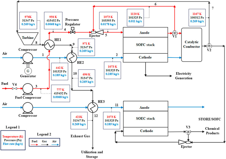
FIGURE 1. Configuration of IGFC hybrid system combining ejectors and SOEC.
By using the compressor, the air is first roughly compressed to the working pressure of the SOFC, which is then heated by the turbine exhaust flow at HE2 before engaging in the electrochemical process on the cathode side of the SOFC. On the anode side, the mixed fuel gas is heated by the turbine exhaust gas at HE1 after being compressed by the fuel compressor. The fuel will then enter the ejector and mix with the secondary flow provided by the pumped fuel cell anode exhaust gas. A pressure regulator is located upstream of the ejector to regulate the gas flow rate and prevent variations brought on by changes in the system pressure. Excess air of the SOFC cathode channel and unreacted fuel of the SOFC fuel electrode channel are assumed to be burned completely in the catalytic combustor. The hot exhaust gas then passes through the turbine for the second stage of electricity generation. The first stage of power generation occurs in SOFC. A portion of this produced power can be used to power electrical devices, while the remaining portion can be used to fuel SOEC electrolysis in the electrolytic cell. At the same time, the CO and H2 generated by the cathode during SOEC electrolysis can also be used to prepare chemical products such as methanol. In the system workflow, in order to prevent waste of energy of the gas turbine stack, air and fuel travel through the HEs to recover the heat from the turbine exhaust.
The operation principles of the IGFC systems are expressed as follows:
1) Mass flow inlet is considered as the boundary condition at the inlet of the ejector.
2) Under stable operating conditions, the inlet pressure of the fuel cell stack is always controlled by a pressure regulator to avoid pressure fluctuations in the system.
3) The outlet pressure of the ejector is set to be approximately equal to the inlet pressure of the fuel cell stack. The pressure is closely related to the operating condition parameters of the fuel cell stack and the entrainment performance of the ejector itself.
4) In the IGFC system, the pressure of the primary flow is regarded as the outlet pressure of the compressor. The pressure regulator can undoubtedly manage the downstream pressure variations to supply the necessary suction for the ejector. The secondary flow pressure of the ejector is identical to the outlet pressure of the fuel cell stack.
The fuel cell voltage is first regarded to be constant. The outlet pressure of the fuel cell stack is lower than its working pressure due to the pressure drop across the stack.
In this study, a 1D SOFC stack model is built. The fuel gas is assumed to be steadily fed to the anode side, which is then diffused into the anode porous electrode for electrochemical reaction. Catalytic action on the catalyst surface converts O2 into O2-, and then O2- is transferred to the anode through the electrolyte layer under the action of electrochemical potential, followed by electrochemical reaction with the fuel gas. The electrochemical reaction is as follows:
To simplify the model complexity, some assumptions are considered:
1) There is no gas leakage during the operation.
2) The working gas is regarded as an ideal gas.
3) The hybrid power generation system always operates in a steady-state condition.
4) The working parameters of each fuel cell are similar (Petrakopoulou et al., 2014).
Since the electrochemical oxidation rate of CO in SOFC is 2–5 times slower than that of hydrogen, the reaction of CO is usually ignored (Ding et al., 2018; Sghaier et al., 2018). Supplementary Table S2 (Wu et al., 2018) lists the electrochemical equations and the governing equations for gas transport, heat exchange, and charge transport of the anode-supported SOFC model. Supplementary Table S3 presents SOFC model parameters and operating conditions.
In this study, a 1D SOEC stack model is built. The addition of SOEC to the system permits effective CO2 collecting and gets it ready for later use and storage. SOFC products can be supplied to SOEC electrolysis. The CO and H2O produced at the cathode during SOEC electrolysis can also be supplied to the SOFC for power generation.
In SOEC, H2O and CO2 diffuse into the cathode catalyst layer, and the co-electric hydrolysis reaction occurs. The resulting oxygen ions are transported through the electrolyte layer to the anode side. The electrochemical reaction process can be expressed as (Wang Y. et al., 2020):
There are also possible chemical reactions including reversible WGSR, and reversible DIR (also called steam reforming reaction, the backward reaction is called methanation reaction) (Du et al., 2019; Wang Y. et al., 2020).
Consider the following assumptions for SOEC in this study:
1) All working gases are regarded as ideal gases.
2) The SOEC is operated in a steady state.
3) Ignore the penetration of gases and electrons in the electrolyte.
4) Due to the low velocity, the gas flow in SOEC is laminar.
The gas-phase component transfer process in the porous electrode in this study is described by the extended Fick’s law (Du et al., 2019):
where
Boundary conditions are expressed as follows
The source term of the charge conservation equation represents the current density due to the electrochemical reaction, derived from the Butler-Volmer equation (Du et al., 2019; Wang Y. et al., 2020):
where
where
Supplementary Table S4 (Fuller et al., 1966; Ni, 2013; Li et al., 2015) presents the definitions of Knudsen diffusion coefficient
The GT model used in this study is mainly composed of a centrifugal compressor and a radial turbine, which performance can be extracted from their characteristic diagrams. Figure 2 illustrates the characteristic diagram of the compressor (Wang et al., 2009; Liu and Weng, 2010).
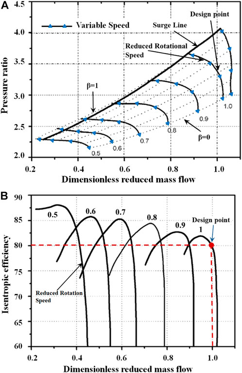
FIGURE 2. Compressor characteristic curve (A) Compressor pressure ratio curve; (B) Compressor efficiency curve.
As can be seen from Figure 2A, each speed curve in the compressor characteristic map corresponds to a wide range of mass flow rates and pressure ratios (Li and Weng, 2011). The pressure ratio and efficiency of the compressor are directly affected by the reduction of mass flow rate and rotational speed (Lv et al., 2015). Second-order polynomials are used to obtain these beta lines in Figure 2A (Li and Weng, 2011). Furthermore, the GT properties can also be obtained according to a similar principle after changing the design parameters (Lv et al., 2016). Supplementary Table S7 presents the design parameters of the GT system.
The power consumption of the air compressor is calculated as follows:
where
The outlet temperature of the air compressor can be approximately calculated as (Lv et al., 2015):
where
The turbine output power is calculated as:
where
The GT output power can be obtained as follows (Zhang et al., 2005):
where
When considering the gas composition of coal, this study refers to the factory test data proposed by Li et al. (Li et al., 2022) in the study of coal gasification coupled supercritical carbon dioxide power cycle system. The data of gasified coal is 52%–60% CO, 22%–29% H2, 7%–10% CO2, 4%–6% H2O, 1%–3% CH4. At the same time, due to the small amount of methane in the gas, the existence of methane was ignored in this study, and the main components of the gas were considered to be H2, CO, CO2, and H2O. In this study, coal gasification gas composed of 45% CO, 35% H2, 10% CO2, and 10% H2O is employed as fuel. The exhaust gas from SOFC contains incomplete reaction components (CO and H2), which can be further eliminated in the catalytic combustor. The main chemical reactions in the catalytic combustor are as follows:
This study considers a system that is fed by metered oxygen for catalytic combustion, based on an adiabatic process. Assuming that the unreacted fuel burns completely in the catalytic combustor, the combustion chamber pressure is considered to be constant and the reaction is assumed to be complete with no oxygen at the outlet. The enthalpy of the reactants and enthalpy of the products will be equal after accounting for combustion efficiency. According to the energy balance equation, the catalytic combustor outlet temperature can be calculated as follows (Li and Weng, 2011):
The ejector can transfer energy from high-energy primary fluid to low-energy secondary fluid through the work done by turbulent mixing and entrainment (Vincenzo et al., 2013). When a high-pressure gas passes through a nozzle, the pressure energy is converted to kinetic energy due to adiabatic expansion. This increases the flow rate but reduces the pressure. Because of the pressure drop of the moving fluid, a low-pressure zone will be formed in the mixing chamber. This causes suction and mixing of the fluid with the primary moving fluid in the mixing chamber. The mixed fluid then passes through a diffuser which causes a better mixing and conversion of kinetic energy to pressure energy. The final result is that the pressure of the mixed fluid at the outlet of the ejector is higher than the low-pressure suction fluid and lower than the high-pressure primary motion fluid.
In the present study, a one-dimensional ejector model with a convergent nozzle is established based on the following assumptions (Liu Z. et al., 2020):
1) The primary flow is considered as the ideal gas.
2) The primary flow of the ejector has a uniform velocity profile in the radial direction.
3) The radial velocity profile of the secondary flow is not considered to be uniform, and there is a velocity boundary layer near the ejector walls.
4) The pressure and temperature of primary and secondary flows are not uniform in the radial direction.
5) Friction loss is calculated based on isentropic relationships.
6) The internal walls of the ejector are considered to be adiabatic.
7) The tapered design of the nozzle is taken into consideration to lessen the likelihood of water vapor condensation in the fuel cell system.
According to the operating condition, the ejector performance can be classified into three operating modes, namely reflow, sub-critical and critical modes. These three operating modes are shown in Figure 3A. The structural diagram of the ejector is illustrated in Figure 3B.
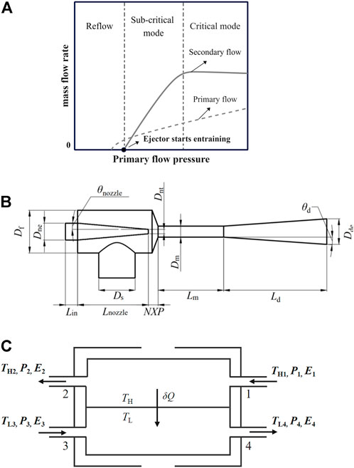
FIGURE 3. (A) Ejector operation mode (Dadvar and Afshari, 2014); (B) Structural diagram of ejector (Liu Z. et al., 2020). (C) Schematic diagram of the countercurrent heat exchanger.
In the present system, the primary flow rate of the ejector is considered as the constant, which is the mixed fuel flow rate at the inlet of the system. By setting a pressure regulating valve upstream of the ejector, the flow deviations caused by residual head and pressure fluctuations in the pipeline can be automatically eliminated. Supplementary Table S8 presents the geometric parameters and operating conditions of the ejector.
The mass flow rate of the ejector secondary flow is calculated as follows (Liu Z. et al., 2020):
where
where
This study employs the following metrics to evaluate ejector performance. The entrainment rate represents the ratio of secondary mass flow rate
The ejector efficiency of compressible flow is defined based on energy which is expressed as follows (Dvorak, 2007):
where
The energy loss of the ejector is calculated by the following equation (Liu Z. R. et al., 2020):
where,
A countercurrent heat exchanger (HE) is utilized in the present study. It is assumed that HE does not involve the phase change process. At the same time, the turbine exhaust gas can directly exchange heat with the gas at the compressor outlet.
The schematic representation of the heat transfer process inside a countercurrent heat exchanger is depicted in Figure 3C. At any arbitrary section of the heat exchanger,
The energy balance of cold and hot streams in the heat exchanger is expressed as follows:
where
The exergy loss of the irreversible heat transfer process is expressed as follows:
The exergy balance equation of the heat exchanger is as follows:
where
where
The performance indices of the IGFC hybrid system may be presented by creating the aforementioned models. The net output power of the IGFC hybrid system is evaluated as follows:
where
The efficiency of the IGFC hybrid system is defined as:
where
In order to accurately estimate the performance of each circulating loop, the thermodynamic parameters and composition of the circulating gas are obtained through iterative calculation. The composition and flow rate of the circulating gas are given first, and the results of the SOFC fuel electrode and SOEC air electrode are used to replace the initial given values in the next calculation cycle until the difference between the given values and the calculated variables is less than 10–6. Figure 4 shows the solution algorithm of the IGFC system using SOFC fuel electrode and SOEC air electrode exhaust gas recirculation, and the program is written on MATLAB platform to simulate the characteristics of the described system.
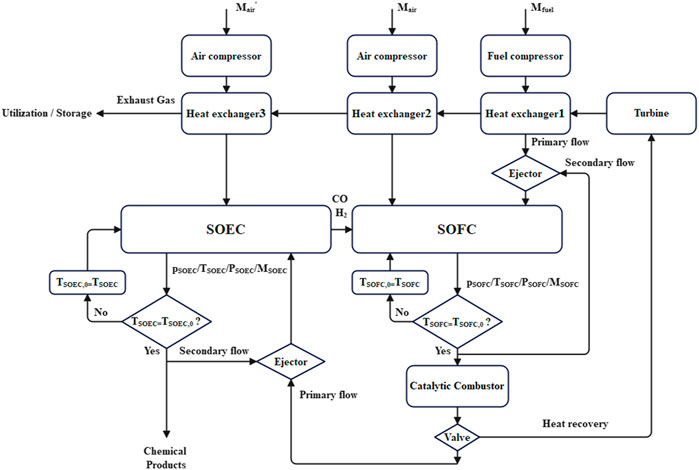
FIGURE 4. Solution algorithm of IGFC system using SOFC fuel electrode and SOEC air electrode exhaust recirculation.
According to the proposed IGFC system model, the preliminary working parameters of each component are listed in Table 1. By using the aforementioned IGFC mathematical models, the operation performance and stream composition of each node at the design point are determined, as shown in Table 2. The molar percentage of mixture at the outlet of SOEC cathode is 22.21% CO, 11.12% H2, 44.43% CO2, and 22.24% H2O. After the initial operation, the performance characteristics of the IGFC hybrid system are presented in Table 3. The system includes 912 single cells in SOFC and 500 high-temperature electrolytic cell stacks. Under the design condition with the working current density of 3000 A m−3, the system output power is 145.90 kW and the electric efficiency is 48.42%. At this condition, the IGFC power generation system can reduce CO2 emissions by 68.53% in comparison with the traditional power plant system without SOEC.
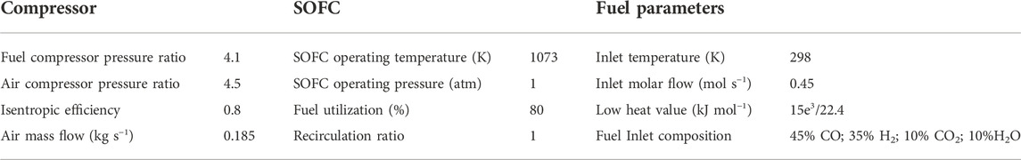
TABLE 1. Preliminary design conditions for the IGFC hybrid system.
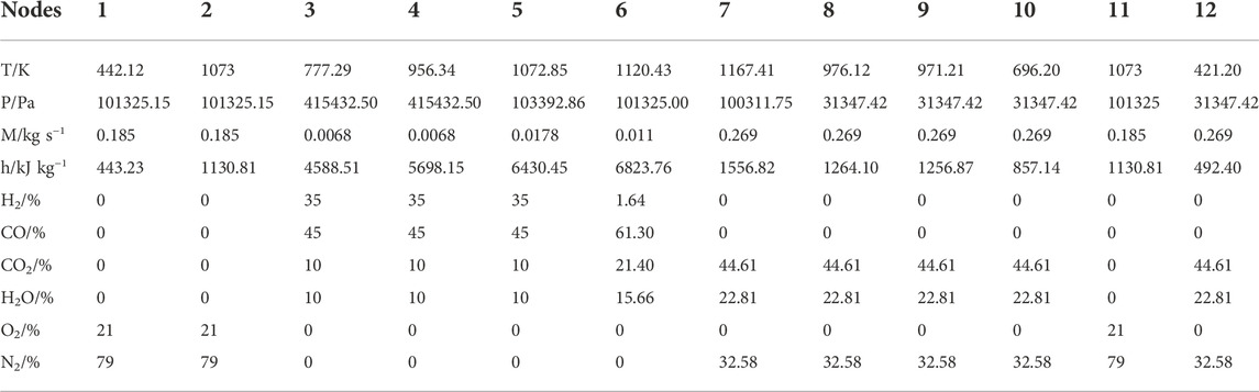
TABLE 2. IGFC each node parameter.
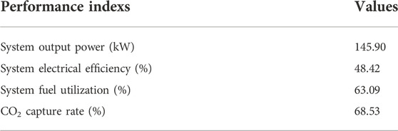
TABLE 3. The IGFC hybrid system performance.
Figure 5 compares the simulation results of the SOFC and SOEC models with experimental data, respectively. In the verification process, the operating voltage of the fuel cell and the electrolytic cell is 1 atm, and their performance at different temperatures (750, 800, and 850°C) are compared. The variation between the SOFC/SOEC model and the experimental data is small. Consequently, the SOFC and SOEC models developed in this work are plausible and appropriate.
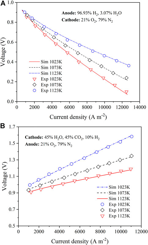
FIGURE 5. Comparison between model polarization curve and experimental polarization curve under different operating conditions (A) SOFC(Wu et al., 2018); (B) SOEC (Du et al., 2019).
This study fully analyzes the effect of ejector primary flow pressure on secondary reflux flow, entrainment ratio, ejector outlet pressure and energy loss. The comparison between the model results and the experimental data is performed in Figure 6A. It can be seen that the simulation results are in good agreement with the experimental data, and the proposed one-dimensional model of the ejector has good reliability.
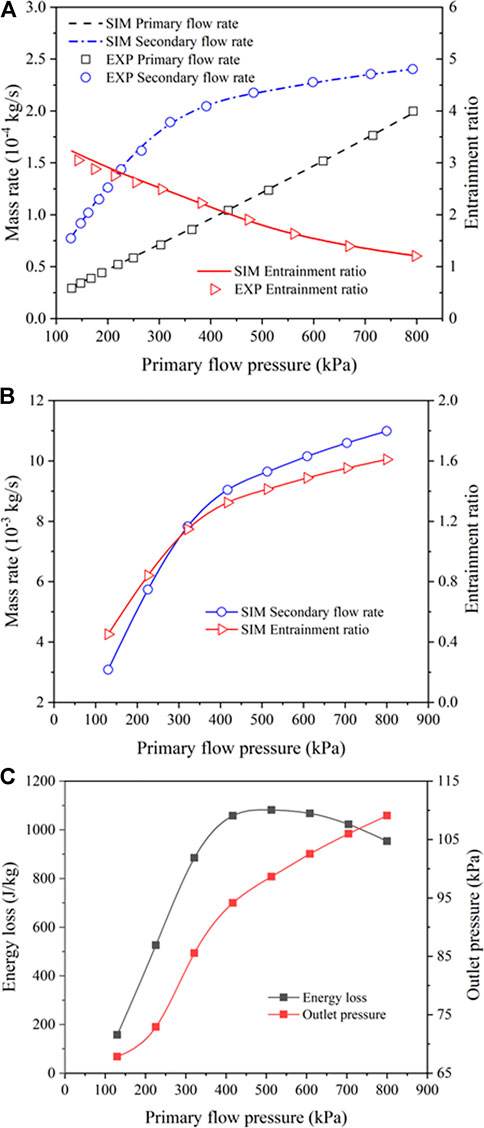
FIGURE 6. (A) The simulation results of the ejector model were compared with the experimental data (Nikiforow et al., 2016); Primary flow pressure pair of ejector (B) mS0 and w; (C) Energy loss and outlet gas pressure.
For the proposed system, the operating results of the model based on the given inlet fuel flow are shown in Figures 6B,C. It can be seen that a large primary flow pressure can significantly improve the secondary reflux flow and thus the entrainment ratio of the ejector. Furthermore, as the primary flow pressure increases, the ejector outlet pressure at the end of the cycle increases, while energy loss of the gas flow increase significantly at first and decreases gradually at the end. As the pressure of the primary flow rises to a subcritical state, the flow of the secondary flow increases rapidly with the increase of the pressure of the primary flow in this state. With the increase of primary flow pressure, the loss coefficient and the Mach number of the suction chamber increase, which leads to an increase in the suction chamber velocity. When the pressure reaches the critical state, the mass flow rate of the secondary flow is basically unchanged. In this case, increasing the primary flow pressure will only increase the primary flow loss coefficient. It can be seen from Eq. 30 that the energy loss Eloss shows a trend of increasing first and then decreasing.
Since the exhaust gas of the SOFC fuel electrode and SOEC air electrode contains unreacted gas, a portion of the exhaust gas can be recycled using the ejectors and fuel pressure in order to improve fuel utilization. According to Riensche et al. (Riensche et al., 1998), the main advantage of anode gas recirculation for fuel cells is that no external steam will be generated in this process.
The present study analyzes the effect of different fuel inlet compositions on SOFC, SOEC, and the system after full combustion in the catalytic combustor. Three times of recirculation can be considered as a complete gas reaction. Five different fuel inlet conditions are considered to examine the mechanism of exhaust gas recirculation, as presented in Supplementary Table S9.
Figure 7 compares the performance of these five different fuel inlet conditions with and without recirculation. It can be seen from Figures 7A,B that the output voltage and electrical efficiency of acyclic SOFC are higher at lower current densities, while the output voltage and electrical efficiency of cyclic SOFC are greater at higher current densities. The greater fuel inlet ratio of CO and H2 is more effective in performance improvement. For a cycle, there are more effective reaction gases and the material conversion rate is faster in the equilibrium condition. Accordingly, it is less difficult to enhance the generation and amplitude change of electrostatic current, causing to increase in exchange current density. In this condition, the overpotential is very close to reaching a certain total current density, and a large exchange current density will reduce the activation loss. In addition, due to more effective gas reactions, more H2O is finally produced which causes a small Nernst voltage. Consequently, regardless of the inlet air composition, the Nernst voltage and activation overpotential of acyclic SOFC are always higher than those of cyclic SOFC. Based on the fuel cell output voltage, if various overvoltage losses are subtracted from the Nernst voltage, there is almost no difference in the output voltage and electrical efficiency for the cases with and without circulating process at low current density. In contrast, at high current density, the electrical efficiency of cyclic SOFC is higher due to larger exchange current density and smaller activation overpotential.
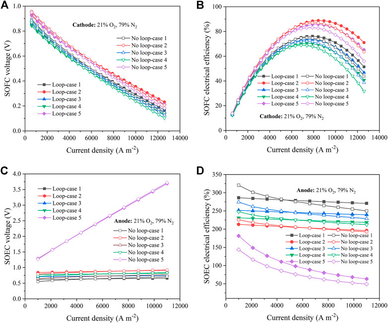
FIGURE 7. Performances under five different fuel inlet schemes (A) Output voltage of SOFC; (B) SOFC electrical efficiency; (C) SOEC electrolytic voltage; (D) SOEC electrolytic efficiency.
The operating temperature of SOEC is given by the outlet temperature of the catalytic combustor. In the case of the fifth fuel inlet condition, the electrolytic voltage is greatly increased and the electrolytic efficiency is significantly reduced. The reason is that the mixed gas temperature at the catalytic combustor outlet is the lowest for this fuel inlet condition compared to that of other fuel inlet conditions. The lower operating temperature decreases the electrolytic efficiency of SOEC and increases the required electrolytic voltage. It can be seen from Figures 7C,D that at lower current densities, the acyclic SOEC has higher electrolysis efficiency and lower electrolysis voltage, while at higher current densities, the cyclic SOEC has greater electrolysis efficiency and lower electrolysis voltage. With the increase of current density, the exchange current density of cyclic SOEC is larger, while its activation overpotential is smaller. Under isothermal conditions and with the progress of recycling, the working voltage and Nernst voltage of SOEC are increased. Accordingly, the working voltage of cyclic SOEC is lower than that of acyclic SOEC at high current density.
The operating results for the system and the GT are illustrated in Figures 8A–C. The following formulas are used to calculate the output power and electrical efficiency of the system:
where
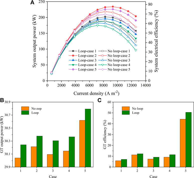
FIGURE 8. Performances under five different fuel inlet schemes (A) System output power and system electrical efficiency; (B) GT output power; (C) GT power generation efficiency.
As shown in Figure 8A, With fixed fuel inlet flow
The impact of main operating parameters on the system performance is studied by direct specification of their operating range. Figures 9A,B examine the effect of SOFC fuel utilization and anode recirculation ratios on SOFC operation efficiency and CO2 enrichment in the system. Fuel utilization and anode recirculation ratios are two important operating parameters that determine the fuel composition of SOFC downstream of the gas turbine. Higher fuel utilization and anode recycling rate can effectively recover a certain amount of hydrogen from anode tail gas as fresh anode fuel. This can improve the electrical efficiency and CO2 enrichment of SOFC. When the fuel utilization is lower than 40%, the electric efficiency of SOFC in conventional generation system is higher than in IGFC system. By enhancement of fuel utilization, the electrical efficiency of SOFC in the IGFC system increases significantly and the gap between SOFC and the traditional power generation system extends. However, high fuel recirculation rate indicates that the exhaust gas contains a small amount of unused fuel. This reduces the net power of the downstream gas turbine and leads to a significant increase in the net overall power of the system. At the operating current density of 3000 A m−3 and by an increase of the fuel utilization ratio from 30% to 90%, the electrical efficiency of SOFC and CO2 enrichment in the IGFC system reach 66.0% and 7.6 mol m−3, respectively, which are improved by 27.3% and 5.8 mol m−3, respectively. When the anode recirculation ratio increases from 0.5 to 0.8, electrical efficiency and CO2 enrichment of SOFC in the IGFC system increase by 9.3% and 2.4 mol m−3, respectively.
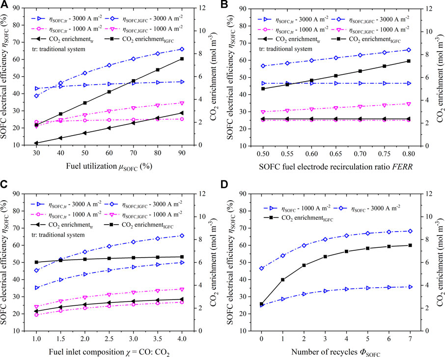
FIGURE 9. Influence of main parameters on CO2 enrichment in SOFC and SOFC electrical efficiency: (A) Fuel utilization
The influence of fuel inlet composition with different CO and CO2 ratios on CO2 enrichment is shown in Figure 9C. On the one hand, the fuel inlet composition with a high CO proportion improves the electric efficiency due to the increase of the fuel quantity of anode effective reaction in SOFC. On the other hand, the high electrical efficiency of SOFC increases CO2 enrichment. It can be seen from Figure 9D that the increase in the number of cycles can support the effective utilization of the fuel involved in the electrochemical reaction. It also increases the amount of effective reaction gas and enhances the electrical efficiency and CO2 enrichment of SOFC.
It is obvious from Figure 9 that an increase in the current density can considerably improve the electrical efficiency of SOFC up to a certain extent. Under the same current density, the IGFC system equipped with the recirculation process can increase the maximum CO2 enrichment and the electrical efficiency of SOFC by 5.1 mol m−3 and 19.5%, respectively compared to the traditional power plants.
In this work, the fully combusted gas in the catalytic combustor can flow to the SOEC branch through the three-way valve connection. Its purpose is to capture CO2 and engage it in the electrolysis process to reduce the amount of CO2 emitted by the system. Because the gases involved in the electrochemical reaction in SOFC are H2 and CO, and the products are H2O and CO2. Therefore, we consider that SOFC and SOEC can be linked, and the products of SOFC can be transported to SOEC for electrolysis. At the same time, the products of SOEC can also be transported to SOFC. In order to make full use of SOFC’s export product, we connect a catalytic combustor between SOFC and SOEC. The CO and H2 are completely combusted by supplying a stoichiometric amount of O2 in the catalytic combustor. This further improves the fuel utilization and output power of the system. Figure 10 shows the impact of main operating parameters on CO2 capture and electrolysis efficiency of SOEC. In this system, the operating temperature of SOEC is determined by the mixed gas temperature at the outlet of the catalytic combustor. As illustrated in Figure 1, three-port valve V2 controls the amount of gas flowing to SOEC. In comparison with traditional power plants, the innovation of the IGFC system is the addition of SOEC as a CO2 capture device to further improve the CO2 capture rate and achieve higher environmental friendliness. The electrolytic products of SOEC can also be transported to SOFC for recycling or they can be reformed into chemical products such as methanol. As shown in Figures 10A,B, enhancement of fuel utilization and cathode recirculation ratio can improve the electrolytic efficiency and capture the amount of CO2 in SOEC, and they can reduce CO2 emissions. In the analysis, the CO2 emission of the traditional power plant is determined according to the CO2 concentration at the catalytic combustor outlet. During analysis of SOEC operation, the upstream SOFC and gas turbine are considered to operate with constant parameters. The inlet fuel component of the IGFC system enters SOEC after being fully burned in SOFC and catalytic combustor, which affects the SOEC as shown in Figure 10C. The inlet fuel with a high proportion of CO has more effective reaction gases CO2 and H2O that enter SOEC after full combustion in the catalytic combustor. This leads to the large power consumption of SOEC, low electrolysis efficiency, and reduced CO2 capture. Figure 10D shows that the higher amount of captured CO2 in SOEC does not correspond to a larger number of SOEC cycles. Examination of 0–7 times of recirculation indicates that CO2 capture is up to 5.4 mol m−3 when SOEC performs one time of recirculation.
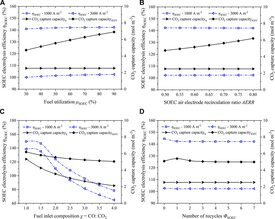
FIGURE 10. Influence of main parameters on CO2 capture and electrolysis efficiency of SOEC: (A) Fuel utilization
Since the upstream equipment of SOEC operates based on fixed parameters, and the proposed SOEC system in the present study operates under constant current density and voltage, some operating parameters such as inlet components and operating temperature are constant during parameter analysis. This leads to little impact on time-varying conditions during the analysis of SOEC electrical efficiency.
Effectiveness analysis of the system is conducted in this study to discuss the impact of the main parameters of the system operation on its overall electrical efficiency. The environmental assessment of the system is mainly performed to examine the impact of utilization of SOEC on the CO2 capture rate of the system. In order to evaluate the impact of the hybrid power system on the environment, this study considers CO2 emission per unit of output power as the evaluation index (Wu et al., 2020), which is expressed by Equations 39, 40. CCR represents the total CO2 capture rate of the system.
It is obvious from the bar charts in Figure 11 that the system equipped with SOEC can significantly reduce the relative emission of CO2. As shown in Figure 11A, by the improvement of SOFC and SOEC fuel utilization, the relative CO2 emission decreases, and the net electrical efficiency and total CO2 capture rate of the system increase. It can be seen from Figure 11B that the relative emission of CO2 is the lowest when the SOFC fuel electrode recirculation ratio (FERR) and the SOEC air electrode recirculation ratio (AERR) are both 0.75. Since traditional power plants are not equipped with SOEC devices for CO2 capture, CO2 emission increases with the growth of the recycling ratio. However, in the IGFC system, the increased SOEC recirculation ratio leads to higher CO2 capture efficiency. So, CO2 emission of the IGFC system continues to decrease and the CO2 capture rate continues to improve with a peak of 80.37% when FERR = AERR = 0.75.
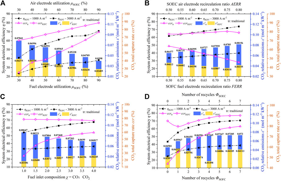
FIGURE 11. Trends of net electrical efficiency, relative CO2 emissions, and total CO2 capture rate of the system with main operating parameters (A) Fuel utilization; (B) Recirculation ratio; (C) Fuel inlet composition
Seven different fuel inlet compositions are considered to study the electrical efficiency and CO2 capture rate of the IGFC system, as presented in Supplementary Table S10. In this study, the fuel inlet compositions with different CO: CO2 ratios are considered, and the proportion of residual gas remains unchanged. In the IGFC system, the fuel inlet with a high CO proportion enters the SOEC after full combustion in the catalytic combustor. This results in high power consumption of the SOEC, low electrolysis efficiency, and reduced CO2 capture, as can be observed in Figure 11C. However, in traditional power plants, fuel inlet with a high CO ratio increases the effective gas amount of electrochemical reaction in SOFC, which enhances the enrichment of CO2 in SOFC. Here, the increase in recirculation times includes the recirculation of SOFC fuel electrode and cathode gas in the system. The rise of recirculation times can properly improve gas utilization. It can be seen from Figure 11D that an increase in the number of cycles does not necessarily lead to better results. Recirculating for the fifth time increases the CO2 enrichment which is caused by SOFC fuel electrode recirculation. After full combustion in the catalytic combustor, power consumption of the downstream SOEC increases, and the electrolysis efficiency decreases. Furthermore, relative CO2 emissions increase which is not favorable for CO2 capture measures of the system. It can be seen that the CCR of the system decreases significantly during the first cycle. When the number of cycles increases, the CCR of the system increases again. This is because there are more effective reaction gases in SOFC and SOEC exhaust gas when no circulation is added. When only one recycle is added, the amount of CO2 captured by SOFC increases significantly. The increase of CO2 content leading to SOEC through catalytic combustor leads to the increase in SOEC power consumption and the decrease in electrolysis efficiency. However, increasing the recirculation will inevitably lead to an increase in SOEC power consumption and an increase in SOFC output power. The overall effect is that the output power of the IGFC system increases. The reduced electrolysis efficiency leads to the inability of SOEC to meet the higher capture rate at the same time as high CO2 enrichment, resulting in an increase in the amount of CO2 at the system outlet and a decrease in the total CO2 capture rate of the system. At the same time, it can be seen that the CO2 capture rate does not increase significantly when the number of recirculations is greater than or equal to 5, and it is no longer necessary to increase the number of recirculations. Therefore, under the comprehensive analysis, when the exhaust gas recirculation ratios of the SOFC fuel electrode and SOEC air electrode are controlled to be equal to 4, the minimum relative CO2 emission of 0.015 mol m−3 kW−1 and the maximum total CO2 capture rate of 87.88% can be obtained.
The most significant difference between this study and other hybrid power generation systems is the implementation of SOEC for CO2 capture. In order to highlight the enhanced performance of the hybrid power system after adding SOEC, fuel utilization of the system is analyzed.
Fuel utilization of the system in the absence and presence of SOEC is expressed by Equations 41, 42, respectively.
where
According to calculations, the fuel utilization rate of the system is 63.09% and 83.40%, before and after using SOEC for capture, respectively. Therefore, under the preliminary design conditions of the proposed system as presented in Table 1, the fuel utilization rate of the system can be improved by about 20.31%, considering the recirculation of the exhaust gas of the system.
The performance of IGFC system configurations is enhanced by adjusting the operating parameters. After analysis, the fuel utilization ratios are

TABLE 4. Optimal operating parameters of the IGFC system.
This research innovatively proposed multi-physics coupled models of the integrated system consisting of SOFC, SOEC, GT, and multiple recirculation circuits. Recirculation loops were configured at the SOFC fuel electrode and SOEC air electrode to improve the CO2 capture rate and electrical efficiency of the system. The interaction between these two types of recirculation was analyzed to determine the optimal recirculation ratio. In addition, parameter analysis was also performed to investigate the impact of fuel utilization, SOFC fuel electrode and SOEC air electrode recirculation ratios, fuel inlet composition, and recirculation times on CO2 capture rate and electrical efficiency. The purpose was to evaluate the influence of coupling among multiple operating parameters on the system performance. It was found that fuel utilization and the number of recirculations were significantly effective on the IGFC system performance. Considering the interaction and thermal coupling between different components, the optimal cycle ratios of both SOFC fuel electrode and SOEC air electrode recirculation loops were obtained to be 0.75. Furthermore, 4 times of recycling were performed to obtain the highest power generation efficiency and CO2 capture rate of the system. When the fuel utilization ratio of SOFC and SOEC increased from 30% to 90%, the relative CO2 emission was decreased by 45%, and the electrical efficiency and total CO2 capture rate of the system were increased by 30% and 22.45%, respectively. In this study, fuel inlet compositions with different CO: CO2 ratios were considered, such that the proportion of residual gas was unchanged. For the fuel inlet composition with CO: CO2 ratio of 4, the highest electrical efficiency of the system could be experienced. After optimization of the design parameters, the power efficiency and CO2 capture rate of the proposed system were 68.47% and 87.88%, respectively which were 20.05% and 59.38% higher than those of traditional power plants. Additionally, the fuel utilization rate was increased from 63.09% to 83.40% (20.31% growth) after optimization of the design parameters. Overall, the cycle structure established in this study can produce an efficient gas conversion system while taking into account the safety constraints of key components as well as the healthy operation of the IGFC hybrid system.
The original contributions presented in the study are included in the article/Supplementary Material, further inquiries can be directed to the corresponding authors.
YW: Conceptualization, Methodology, Software, Validation, Formal analysis, Investigation, Resources, Data curation, Writing–original draft, Writing–review and editing, Visualization. CW: Methodology, Software, Writing–review and editing. YW: Software, Investigation, Writing–review and editing. ZY: Writing–review and editing, Project administration, Funding acquisition. QD: Conceptualization, Methodology, Supervision, Writing–review and editing, Project administration, Funding acquisition. KJ: Conceptualization, Formal analysis, Writing–review and editing, Supervision, Project administration, Funding acquisition.
This work is supported by the National Natural Science Foundation of China (Grant No. 51976138).
The authors declare that the research was conducted in the absence of any commercial or financial relationships that could be construed as a potential conflict of interest.
All claims expressed in this article are solely those of the authors and do not necessarily represent those of their affiliated organizations, or those of the publisher, the editors and the reviewers. Any product that may be evaluated in this article, or claim that may be made by its manufacturer, is not guaranteed or endorsed by the publisher.
The Supplementary Material for this article can be found online at: https://www.frontiersin.org/articles/10.3389/fenrg.2022.1017829/full#supplementary-material
Adams, T. A., and Barton, P. I. (2010). High-efficiency power production from coal with carbon capture. AIChE J. 56 (12), 3120–3136. doi:10.1002/aic.12230
Bohm, M. C., Herzog, H. J., Parsons, J. E., and Sekar, R. C. (2007). Capture-ready coal plants - options, technologies and economics. Int. J. Greenh. Gas Control 1 (1), 113–120. doi:10.1016/s1750-5836(07)00033-3
Buonomano, A., Calise, F., d'Accadia, M. D., Palombo, A., and Vicidomini, M. (2015). Hybrid solid oxide fuel cells-gas turbine systems for combined heat and power: A review. Appl. Energy 156, 32–85. doi:10.1016/j.apenergy.2015.06.027
Dadvar, M., and Afshari, E. (2014). Analysis of design parameters in anodic recirculation system based on ejector technology for pem fuel cells: A new approach in designing. Int. J. Hydrogen Energy 39 (23), 12061–12073. doi:10.1016/j.ijhydene.2014.06.046
Dang Saebea, S. A., Authayanun, S., Patcharavorachot, Y., and Arpornwichanop, A. (2016). Effect of anode–cathode exhaust gas recirculation on energy recuperation in a solid oxide fuel cell-gas turbine hybrid power system. Energy 94, 218–232. doi:10.1016/j.energy.2015.10.138
Dincer, I., and Rosen, M. A. (1999). Energy, environment and sustainable development. Appl. Energy 64 (1-4), 427–440. doi:10.1016/s0306-2619(99)00111-7
Ding, X. Y., Lv, X. J., and Weng, Y. W. (2018). “Effect of operating parameters on performance and safety evaluation of a biogas-fueled SOFC/GT hybrid system,” in 10th international conference on applied energy (ICAE) (AMSTERDAM: Elsevier Science Bv), 1842–1849.
Du, Y. M., Qin, Y. Z., Zhang, G. B., Yin, Y., Jiao, K., and Du, Q. (2019). Modelling of effect of pressure on co-electrolysis of water and carbon dioxide in solid oxide electrolysis cell. Int. J. Hydrogen Energy 44 (7), 3456–3469. doi:10.1016/j.ijhydene.2018.12.078
Dvorak, V. (2007). “Shape optimization and computational analysis of axisymmetric ejector,” in Proceedings of the 8th international symposium on experimental and computational aerothermodynamics of internal flows (France-Lyon.
Fuller, E. N., Schettler, P. D., and Giddings, J. C. (1966). New method for prediction of binary gas-phase diffusion coefficients. Ind. Eng. Chem. 58 (5), 18–27. doi:10.1021/ie50677a007
Guan, G. Q., Fushimi, C., Tsutsumi, A., Ishizuka, M., Matsuda, S., Hatano, H., et al. (2010). High-density circulating fluidized bed gasifier for advanced IGCC/IGFC-Advantages and challenges. Particuology 8 (6), 602–606. doi:10.1016/j.partic.2010.07.013
Huang, S. L., Yang, C., Chen, H., Zhou, N. N., and Tucker, D. (2022). Coupling impacts of SOFC operating temperature and fuel utilization on system net efficiency in natural gas hybrid SOFC/GT system. Case Stud. Therm. Eng. 31, 101868. doi:10.1016/j.csite.2022.101868
Jinwei Chen, Y. C., Zhang, H., and Weng, S. (2018). Effect of different operating strategies for a SOFC-GT hybrid system equipped with anode and cathode ejectors. Energy 163, 1–14. doi:10.1016/j.energy.2018.08.032
Li, M., Brouwer, J., Powers, J. D., and Samuelsen, G. S. (2009). “A finite volume SOFC model for coal-based integrated gasification fuel cell system Analysis,” in 7th international conference on fuel cell science, engineering and technology (NEW YORK: Amer Soc Mechanical Engineers), 677–686.
Li, M., Brouwer, J., Rao, A. D., and Samuelsen, G. S. (2011). Application of a detailed dimensional solid oxide fuel cell model in integrated gasification fuel cell system design and analysis. J. Power Sources 196 (14), 5903–5912. doi:10.1016/j.jpowsour.2011.02.080
Li, W. Y., Shi, Y. X., Luo, Y., and Cai, N. S. (2015). Elementary reaction modeling of solid oxide electrolysis cells: Main zones for heterogeneous chemical/electrochemical reactions. J. Power Sources 273, 1–13. doi:10.1016/j.jpowsour.2014.08.120
Li, Y., and Weng, Y. W. (2011). Performance study of a solid oxide fuel cell and gas turbine hybrid system designed for methane operating with non-designed fuels. J. Power Sources 196 (8), 3824–3835. doi:10.1016/j.jpowsour.2011.01.011
Li, Z. K., Tian, S. F., Zhang, D., Chang, C. Z., Zhang, Q., and Zhang, P. J. (2022). Optimization study on improving energy efficiency of power cycle system of staged coal gasification coupled with supercritical carbon dioxide. Energy 239, 122168. doi:10.1016/j.energy.2021.122168
Liu, A. G., and Weng, Y. W. (2010). Performance analysis of a pressurized molten carbonate fuel cell/micro-gas turbine hybrid system. J. Power Sources 195 (1), 204–213. doi:10.1016/j.jpowsour.2009.07.024
Liu, Z., Liu, Z., Jiao, K., Yang, Z., and Du, Q. (2020a). Numerical investigation of ejector transient characteristics for a 130-kW PEMFC system. Int. J. Energy Res. 44 (1), 3697–3710. doi:10.1002/er.5156
Liu, Z. R., Liu, Z., Jiao, K., Yang, Z. R., Zhou, X., and Du, Q. (2020b). Numerical investigation of ejector transient characteristics for a 130-kW PEMFC system. Int. J. Energy Res. 44 (5), 3697–3710. doi:10.1002/er.5156
Lv, X. J., Liu, X., Gu, C. H., and Weng, Y. W. (2016). Determination of safe operation zone for an intermediate-temperature solid oxide fuel cell and gas turbine hybrid system. Energy 99, 91–102. doi:10.1016/j.energy.2016.01.047
Lv, X. J., Lu, C. H., Wang, Y. Z., and Weng, Y. W. (2015). Effect of operating parameters on a hybrid system of intermediate-temperature solid oxide fuel cell and gas turbine. Energy 91, 10–19. doi:10.1016/j.energy.2015.07.100
Mahlia, T. M. I., Saktisandan, T. J., Jannifar, A., Hasan, M. H., and Matseelar, H. S. C. (2014). A review of available methods and development on energy storage; technology update. Renew. Sustain. Energy Rev. 33, 532–545. doi:10.1016/j.rser.2014.01.068
Ni, M. (2012). 2D thermal modeling of a solid oxide electrolyzer cell (SOEC) for syngas production by H2O/CO2 co-electrolysis. Int. J. Hydrogen Energy 37 (8), 6389–6399. doi:10.1016/j.ijhydene.2012.01.072
Ni, M. (2013). Modeling and parametric simulations of solid oxide fuel cells with methane carbon dioxide reforming. Energy Convers. Manag. 70, 116–129. doi:10.1016/j.enconman.2013.02.008
Nikiforow, K., Koski, P., Karimaki, H., Ihonen, J., and Alopaeus, V. (2016). Designing a hydrogen gas ejector for 5 kW stationary PEMFC system - CFD-modeling and experimental validation. Int. J. Hydrogen Energy 41 (33), 14952–14970. doi:10.1016/j.ijhydene.2016.06.122
Parikh, J., and Lior, N. (2009). Energy and its sustainable development for India, editorial introduction and commentary to the special issue of energy - the international journal. Energy 34 (8), 923–927. doi:10.1016/j.energy.2009.07.001
Park, J., Li, P. W., and Bae, J. (2012). Analysis of chemical, electrochemical reactions and thermo-fluid flow in methane-feed internal reforming SOFCs: Part I - modeling and effect of gas concentrations. Int. J. Hydrogen Energy 37 (10), 8512–8531. doi:10.1016/j.ijhydene.2012.02.110
Park, S. K., Ahn, J. H., and Kim, T. S. (2011a). Performance evaluation of integrated gasification solid oxide fuel cell/gas turbine systems including carbon dioxide capture. Appl. Energy 88 (9), 2976–2987. doi:10.1016/j.apenergy.2011.03.031
Park, S. K., Kim, T. S., Sohn, J. L., and Lee, Y. D. (2011b). An integrated power generation system combining solid oxide fuel cell and oxy-fuel combustion for high performance and CO2 capture. Appl. Energy 88 (4), 1187–1196. doi:10.1016/j.apenergy.2010.10.037
Petrakopoulou, F., Lee, Y. D., and Tsatsaronis, G. (2014). Simulation and exergetic evaluation of CO2 capture in a solid-oxide fuel-cell combined-cycle power plant. Appl. Energy 114, 417–425. doi:10.1016/j.apenergy.2013.09.034
Prabu, V., and Jayanti, S. (2012). Underground coal-air gasification based solid oxide fuel cell system. Appl. Energy 94, 406–414. doi:10.1016/j.apenergy.2012.01.040
Riensche, E., Meusinger, J., Stimming, U., and Unverzagt, G. (1998). Optimization of a 200 kW SOFC cogeneration power plant. Part II: Variation of the flowsheet. J. Power Sources 71 (1-2), 306–314. doi:10.1016/s0378-7753(97)02726-2
Sghaier, S. F., Khir, T., and Ben Brahim, A. (2018). Energetic and exergetic parametric study of a SOFC-GT hybrid power plant. Int. J. Hydrogen Energy 43 (6), 3542–3554. doi:10.1016/j.ijhydene.2017.08.216
Spallina, V., Romano, M. C., Campanari, S., and Lozza, G. (2011). A SOFC-based integrated gasification fuel cell cycle with CO2 capture. J. Eng. Gas. Turbine. Power 133 (7), 10. doi:10.1115/1.4002176
Spliethoff, H. (2010). Power generation from solid fuels, coal-fuelled combined cycle power plants, 469–628. doi:10.1007/978-3-642-02856-4_7
Stempien, J. P., Ding, O. L., Sun, Q., and Chan, S. H. (2012). Energy and exergy analysis of Solid Oxide Electrolyser Cell (SOEC) working as a CO2 mitigation device. Int. J. Hydrogen Energy 37 (19), 14518–14527. doi:10.1016/j.ijhydene.2012.07.065
Trembly, J. P., Gemmen, R. S., and Bayless, D. J. (2007). The effect of IGFC warm gas cleanup system conditions on the gas-solid partitioning and form of trace species in coal syngas and their interactions with SOFC anodes. J. Power Sources 163 (2), 986–996. doi:10.1016/j.jpowsour.2006.10.020
Vincenzo, L., Pagh, N. M., and Knudsen, K. S. (2013). Ejector design and performance evaluation for recirculation of anode gas in a micro combined heat and power systems based on solid oxide fuel cell. Appl. Therm. Eng. 54 (1), 26–34. doi:10.1016/j.applthermaleng.2013.01.021
Wang, X. S., Lv, X. J., and Weng, Y. W. (2020a). Performance analysis of a biogas-fueled SOFC/GT hybrid system integrated with anode-combustor exhaust gas recirculation loops. Energy 197, 117213. doi:10.1016/j.energy.2020.117213
Wang, Y., Du, Y. M., Ni, M., Zhan, R. B., Du, Q., and Jiao, K. (2020b). Three-dimensional modeling of flow field optimization for co-electrolysis solid oxide electrolysis cell. Appl. Therm. Eng. 172, 114959. doi:10.1016/j.applthermaleng.2020.114959
Wang, Y. Z., Yoshiba, F., Kawase, M., and Watanabe, T. (2009). Performance and effective kinetic models of methane steam reforming over Ni/YSZ anode of planar SOFC. Int. J. Hydrogen Energy 34 (9), 3885–3893. doi:10.1016/j.ijhydene.2009.02.073
Wu, C. R., Yang, Z. R., Huo, S., Najmi, A. U. H., Du, Q., and Jiao, K. (2018). Modeling and optimization of electrode structure design for solid oxide fuel cell. Int. J. Hydrogen Energy 43 (31), 14648–14664. doi:10.1016/j.ijhydene.2018.05.152
Wu, Z., Zhu, P. F., Yao, J., Zhang, S. G., Ren, J. W., Yang, F. S., et al. (2020). Combined biomass gasification, SOFC, IC engine, and waste heat recovery system for power and heat generation: Energy, exergy, exergoeconomic, environmental (4E) evaluations. Appl. Energy 279, 115794. doi:10.1016/j.apenergy.2020.115794
Yang, Y. P., Guo, X. Y., and Wang, N. L. (2010). Power generation from pulverized coal in China. Energy 35 (11), 4336–4348. doi:10.1016/j.energy.2009.05.006
Zhang, H. S., Weng, S. L., and Su, M. (2005). “Dynamic modeling and simulation of distributed parameter heat exchanger,” in 50th ASME turbo-expo 2005 (NEW YORK: Amer Soc Mechanical Engineers), 327–333.
Zhang, N., Lior, N., and Jin, H. G. (2011). The energy situation and its sustainable development strategy in China. Energy 36 (6), 3639–3649. doi:10.1016/j.energy.2011.01.035
Zheng, Y. F., Li, Q. S., Guan, W. B., Xu, C., Wu, W., and Wang, W. G. (2014). Investigation of 30-cell solid oxide electrolyzer stack modules for hydrogen production. Ceram. Int. 40 (4), 5801–5809. doi:10.1016/j.ceramint.2013.11.020
Zhou, J. Y., Wang, Z., Han, M. F., Sun, Z. H., and Sun, K. H. (2022). Optimization of a 30 kW SOFC combined heat and power system with different cycles and hydrocarbon fuels. Int. J. Hydrogen Energy 47 (6), 4109–4119. doi:10.1016/j.ijhydene.2021.11.049
An Anode
am Equal area mixing pipe
act Activation state
ca Cathode
cc Catalytic combustor
con Concentration
de Diffuser extension
D Diffusion coefficient (m2 s−1) Diffuser
ele Electronic
eff Effective
ej Ejector
F Suction chamber
G Gas phase
I Gas species
in Inlet
ion Ionic
M Molecular weight (kg mol−1) or mass flow rate (kg s−1) Equal diameter mixing tube
ne Nozzle extension
nt Nozzle throat diameter
S Source term (kg m−3 s−1 or mol m−3 s−1) Secondary flow
ocv Open circuit voltage
out Outlet
ref Reference state
tpb Three-phase boundary length
H2 Hydrogen
H2O Steam
CO Carbon monoxide
CO2 Carbon dioxide
0 Standard state
AERR SOEC air electrode recirculation ratio
CCR CO2 total capture rate (%)
CC Catalytic Combustor
FERR SOFC fuel electrode recirculation ratio
GT Gas Turbine
HE Heat exchanger
rec Recirculation ratio
LHV Lower heat value (kJ mol−1)
IGFC Integrated Coal Gasification Fuel Cell Combined Cycle
SOFC Solid Oxide Fuel Cell
SOEC Solid Oxide Electrolytic Cell
Keywords: IGFC, hybrid system, CO2 enrichment, recirculation, CO2 capture
Citation: Wang Y, Wu C, Wang Y, Yang Z, Du Q and Jiao K (2023) Assessment of CO2 enrichment mechanism in integrated coal gasification fuel cell combined cycle system with carbon capture. Front. Energy Res. 10:1017829. doi: 10.3389/fenrg.2022.1017829
Received: 12 August 2022; Accepted: 16 September 2022;
Published: 06 January 2023.
Edited by:
Lin Qiu, University of Science and Technology Beijing, ChinaReviewed by:
Dibyendu Roy, Durham University, United KingdomCopyright © 2023 Wang, Wu, Wang, Yang, Du and Jiao. This is an open-access article distributed under the terms of the Creative Commons Attribution License (CC BY). The use, distribution or reproduction in other forums is permitted, provided the original author(s) and the copyright owner(s) are credited and that the original publication in this journal is cited, in accordance with accepted academic practice. No use, distribution or reproduction is permitted which does not comply with these terms.
*Correspondence: Yang Wang, MzAxMjIwMTMxNkB0anUuZWR1LmNu; Qing Du, ZHVxaW5nQHRqdS5lZHUuY24=; Kui Jiao, a2ppYW9AdGp1LmVkdS5jbg==
Disclaimer: All claims expressed in this article are solely those of the authors and do not necessarily represent those of their affiliated organizations, or those of the publisher, the editors and the reviewers. Any product that may be evaluated in this article or claim that may be made by its manufacturer is not guaranteed or endorsed by the publisher.
Research integrity at Frontiers
Learn more about the work of our research integrity team to safeguard the quality of each article we publish.