 Pengcheng Yang
 Yonggang Peng
 Yanghong Xia
 Wei Wei
- The College of Electrical Engineering, Zhejiang University, Hangzhou, China
This study proposes a unified voltage regulation and maximum power point tracking (MPPT) method for photovoltaic (PV) sources in islanded direct current (DC) microgrids based on modified model predictive control (MPC). The method enables the PV sources to track the maximum power and serve as voltage sources for DC-bus voltage regulation when their available power is sufficient. Based on the proposed modified predictive model, the desired duty cycles can be calculated and directly applied to the PV sources in a constant switching frequency without a modulator. Real-time laboratory tests show that the PV sources can support the DC-bus voltage without energy storage (ES) and can proportionally share the load. Moreover, power oscillations and voltage ripples of the modified MPC get greatly attenuated compared with the traditional MPC under the same sampling frequency.
1 Introduction
Currently, photovoltaic (PV) generation is becoming one of the most promising renewable power sources due to the continuous reduction in the cost of PV cells. Their DC output makes the DC microgrid an ideal solution to integrate distributed PV sources and supply local loads without the inversion stage (JacksonJusto et al., 2013; Dragičević et al., 2016; Kumar et al., 2017; Meng et al., 2017). A typical DC microgrid with multiple PV sources is shown in Figure 1. To make full use of solar energy, the maximum power point tracking (MPPT) method has been developed for PV sources in the past decades (Bollipo et al., 2020; Vicente et al., 2020). In DC microgrids, however, the maximum power output of PV sources may exceed the local demand and any available energy storage (ES) capacity, and the consequent power imbalance may result in DC-bus overvoltage and ES overcharging problems in the islanded model (Ullah et al., 2020).
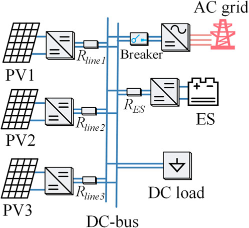
FIGURE 1. Dc microgrid with multiple PV sources.
Limiting the generation of PV sources is a common solution to these problems. Supported by centralized communication for collecting load data, limited generation of PV sources can be determined to balance the bus voltage (Wandhare and Agarwal, 2011). Based on global information, a two-stage robust optimal PV dispatch model was proposed to satisfy the voltage constraints in case of the PV generation surplus load demand (Ding et al., 2017). In the study by Nguyen et al. (2019), combined with voltage regulators and switched capacitors, a comprehensive formulation of PV generation dispatch was studied to prevent the system from voltage violation and reverse power flow. Based on fast communication and global information, the abovementioned centralized PV generation regulation methods have heavy communication burdens and may suffer from a single point of failure.
The high cost and reliability concerns have motivated communication-free solutions. Based on the local DC bus signaling, a distributed mode switching strategy for the PV source was proposed (Tonkoski and Lopes, 2011; Ghosh et al., 2017). Once the bus overvoltage was detected, the MPPT controller was switched off, and the voltage regulation controller was motivated to linearly decrease the injected power until the bus voltage dropped to the rated value. However, the accompanying fluctuation deteriorated the bus voltage during the controller switching process. In the past years, droop-based control for PV sources has been successfully applied without a controller switch (Mahmood et al., 2015; Liu et al., 2016). Accordingly, the local DC-bus voltage is measured and utilized as feedback to regulate the PV operation point autonomously when the available maximum power is excessive. However, these controls are designed for cascaded converters with a two-stage structure and cannot be directly applied to one-stage structures. By introducing the
Over the past decades, model predictive control (MPC) has been widely adopted to power electronics as a promising control method due to its robustness, excellent transient characteristics, and easiness to contain nonlinearities, constraints, and multi objectives (Quevedo et al., 2012; Dragičević, 2018). Instead of designing control loops and tuning parameters in traditional controls, a cost function is designed to evaluate the prediction and track the reference by minimizing the cost function in the MPC. In the study by Hu et al. (2019), a multi-objective MPC was designed for doubly-fed wind generators to regulate power and smooth grid connection; in addition, the controller was simple, without using any proportion integration (PI) regulators, current loops, and switching tables. The interrelations among the load current, circulating current, and capacitor voltages complicate the modular multilevel converters (MMCs) control. A weighted MPC based on a normalized cost function is proposed to achieve stable and balanced voltage and current control with reduced circulating current in various operating conditions for MMC (Ben-Brahim et al., 2016). In the study by Hu et al. (2021), a comprehensive review was present for individual and interconnected microgrids with MPC, which showed competitive advantages in bus voltage regulation, frequency recovery, and economic optimization compared with traditional controls. As for the PV sources, the former MPCs mainly focus on MPPT with a higher convergence speed under changing conditions and less ripple during the steady state (Lashab et al., 2018; Lashab et al., 2019). Still, voltage regulation with MPC is rarely studied for PV sources. In the study by Shadmand et al. (2014), MPPT and voltage regulation were realized by the inner MPPT-MPC and the outer droop-MPC, adopted separately on two cascaded converters. The voltage/current of PV sources cannot be obtained by the outer droop-MPC; hence, the desired power of the droop-MPC may not match the available power of PV sources. Therefore, voltage regulation needs to take the PV voltage/current into consideration in order to predict the available maximum power. The abovementioned MPCs emerged with a finite control set (FCS) appearance. It works with a variable switching frequency, which leads to a widespread harmonics spectrum for voltage/current waveforms, limiting the filter design and increasing the switching losses (Ahmad et al., 2018). As such, the continuous control set model predictive control (CCS-MPC) is designed and applied to a PV system with a constant switching frequency (Errouissi et al., 2016a; Errouissi et al., 2016b), while the voltage regulation is not involved in those research work.
In this study, a unified voltage regulation and MPPT control is designed for PV sources in islanded DC microgrids based on the modified MPC. With the proposed control, the PV sources can autonomously share power appropriately and regulate the DC-bus voltage without any energy storage or track the maximum power point (MPP) once their power output is not enough to feed the load. The comparison between the proposed method and the existing control methods is shown in Table 1, and the above superiorities are attributed to the following designed modifications:
1) By introducing the PV characteristics, a modified predictive model for PV sources is proposed for a more precise prediction; in addition, the desired duty cycles can be calculated and directly applied to the PV sources in a constant switching frequency without a modulator.
2) Taking both the operating point of PV sources and the DC-bus voltage into consideration, the unified PV current reference can be determined to regulate the DC-bus voltage when the available maximum power is redundant or track the maximum power point (MPP) when their power is not sufficient to feed the load.
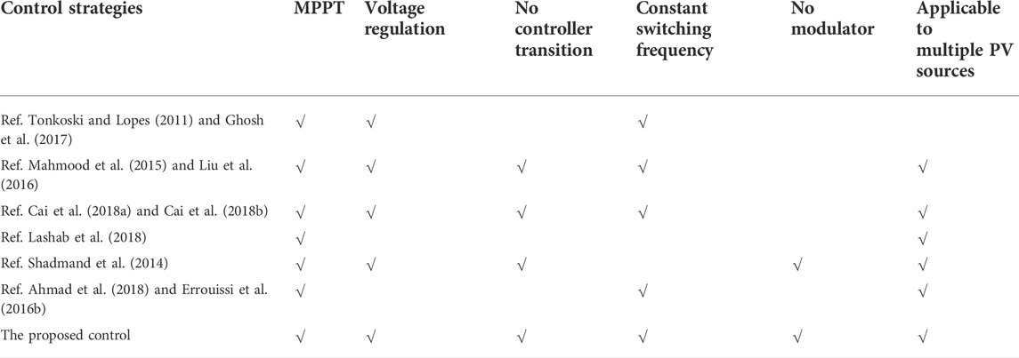
TABLE 1. Comparison of control strategies.
A modified predictive model for PV sources is first proposed for a more precise prediction in Section 2, which modifies the duty cycle calculation of MPC. Then, the voltage regulation and MPPT are integrated according to the operating point of PV sources in Section 3, and the reference value is generated for MPC. According to the modified predictive model and generated reference value, the duty cycle is finally determined and adopted by the converters without modulation. HIL tests are conducted to verify the proposed control, and the comparisons and robustness tests are presented in Section 4.
2 Modified MPC for PV sources
2.1 Review of FCS-MPC for PV sources
For the PV source in the DC microgrid, a boost converter–based model is studied, as shown in Figure 2, and its dynamic model can be written as
where Land C are the coefficients of the LC filter.
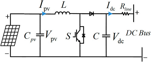
FIGURE 2. Topology of PV sources.
To get the prediction value of PV sources, the discrete-time model is derived from Eq. 1 by using Euler’s forward-difference law with sampling frequency
where k denotes the present value at the sampling time kT, and k+1 denotes the predicted value at the next sampling time.
To evaluate the prediction, a cost function is defined as
where
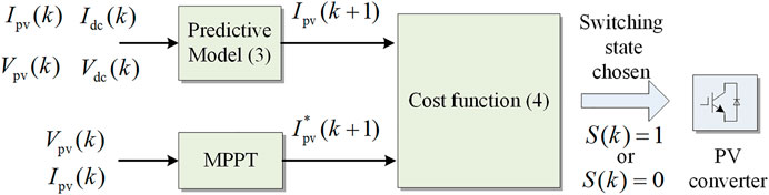
FIGURE 3. Traditional FCS-MPC for PV sources.
In the FCS-MPC,
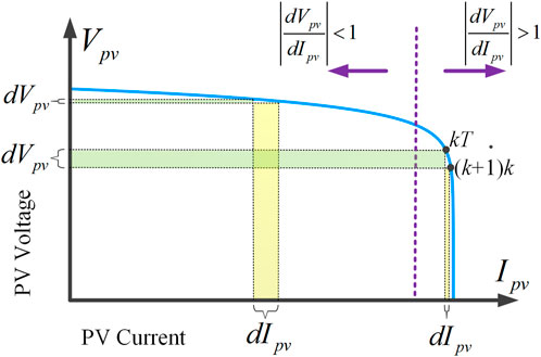
FIGURE 4. V-I characteristic of PV array.
2.2 Modified MPC for PV sources
In the traditional FCS-MPC for PV sources, only the converter is modeled, and the model of PV array is rarely considered, which limits the accuracy of the predictive model. In this study, a more precise predictive model of PV sources is obtained by modifying
The
where
where
According to Eq. 7, the slope
which costs a large computation. To simply the numerical computation, the former slope
Comparing the two slopes in Eqs 8 and 9, the slope
Combining Eqs 5, 6, and 10, the modified predictive model with the PV characteristic can be written as
Once
By limiting
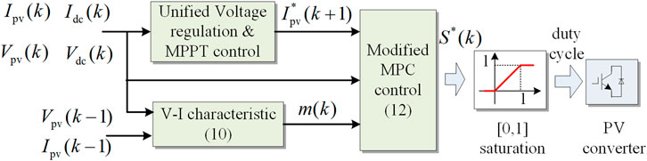
FIGURE 5. Proposed modified MPC for PV sources.
3 Unified voltage regulation and MPPT control for PV sources
3.1 Voltage regulation control
For the PV sources, the participation in voltage regulation has been an increasing demand for the islanded DC microgrid system. The droop control is commonly adapted to regulate the voltage and share the load among multi-sources. In the predictive model, the droop control can be expressed as
where
To maintain the reference DC-bus voltage
where M is a filter coefficient to limit the capacitor’s charging power. In the voltage regulation control, the required power of the PV source is the sum of output power and charging power. According to the power balance, the provided power
where
By setting the
3.2 Unified control for PV sources
Different from regulating the voltage of DC-bus, the MPPT control tries to extract the maximum power. The corresponding MPPT algorithm, such as Perturb and Observe (P&O) or incremental conductance (INC) method, can generate a reference current
Another crucial contribution of this study is to unify voltage regulation and MPPT control. In the MPC-based control, the reference in the cost function plays a key role in determining the final behavior of the converter. In the proposed unified control, the coordination between DC-bus voltage regulation and MPPT is realized by selecting the corresponding voltage regulation reference
(1)
(2)
(3)
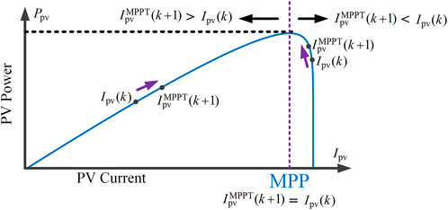
FIGURE 6. Operation regions of PV sources.
Figure 7 shows the simplified flowchart of the aforementioned reference selection mechanism. By evaluating the reference values
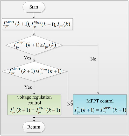
FIGURE 7. Flowchart of the reference selection mechanism.
4 Verification and discussion
To verify the efficacy of the proposed unified control, the hardware in loop tests are conducted using RT-LAB and STM32F407MCUs, as shown in Figure 8. The DC microgrid with three PV sources, as shown in Figure 1, is tested. PVs’ power output ratio is 1∶1.38∶1.78 under the same temperature and solar irradiation conditions. As such, their droop coefficients are set as 0.5 V/A, 0.36 V/A, and 0.28 V/A to proportionally share the load, and their normal DC voltage
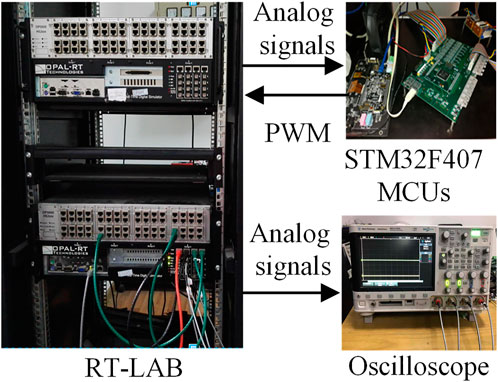
FIGURE 8. HIL test facilities.
4.1 Bus voltage regulation test
Figure 9 shows the system responses under step-changes of the load and solar irradiation. In the initial State I, both the PV sources and the ES are connected to regulate the DC-bus voltage. In State II, the ES is disconnected from the DC-bus. The initial load
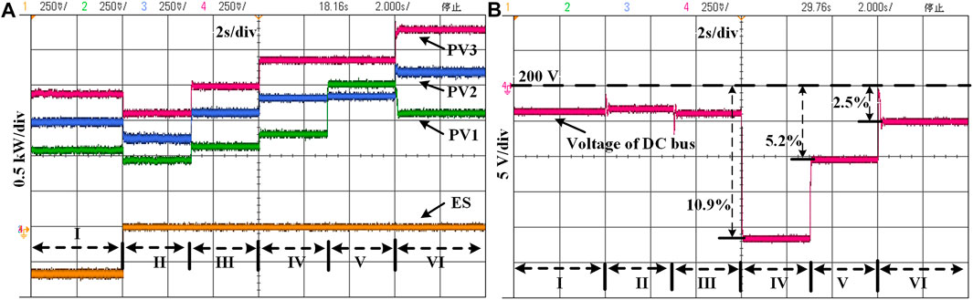
FIGURE 9. System responses under step-changed load and solar irradiation (A) Power outputs of PV1, PV2, PV3, and ES. (B) DC-bus voltage.
Figure 9A shows the power outputs of the PV sources and the ES, and Figure 9B shows the response of the DC-bus voltage. In State I, the ES absorbs the excessive PV power to maintain the power balance. In State II, the ES is removed, and the PV sources compensate their power outputs to maintain the DC-bus voltage without the ES. When the load increases in State III, the PV sources proportionally increase their power outputs. In State IV, the load further increases and exceeds the available maximum power. The PV sources provide their maximum power, which is still not sufficient to feed the load and maintain the DC-bus voltage, resulting in a 10.9% voltage drop. In State V, the power output of PV1 increases since its solar irradiation rises; however, the total power output of the PV sources is still not enough to maintain the DC-bus voltage. Thus, the PV sources track their MPPs, and the voltage drop is alleviated to 5.2%. In State VI, with the solar irradiations of PV2 and PV3 increasing, the total available maximum power is sufficient for the load demand, and the PV sources coordinately regulate the DC-bus voltage. The power sharing results in different states are listed in Table 2. It is shown that the power sharing ratio is close to the designed ratio of 1∶1.38∶1.78 under the same solar irradiation condition. If the solar irradiations of PV sources are different, the proposed control will not maintain the power output according to the sharing ratio when the power is not sufficient, which can make full use of solar energy and alleviate the DC-bus voltage deviation.
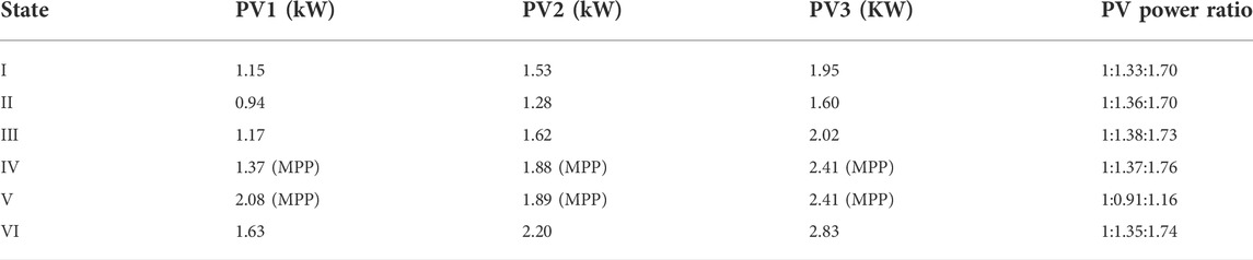
TABLE 2. Power outputs of three PV arrays.
With the proposed unified control, the PV sources can regulate the DC-bus voltage when their available maximum power is sufficient; otherwise, track the MPP to compensate for the high load. The load can be shared proportionally according to the capacities of PV sources without communication links.
4.2 Comparison test
The MPPT and voltage regulation dynamic responses of PV sources with different control methods are compared in Figure 10. The solar irradiation increases from 800 to 1,200 W/m2 in State II in order to test the MPPT dynamic response. The ES is removed in State III to test the dynamic response of the voltage regulation.
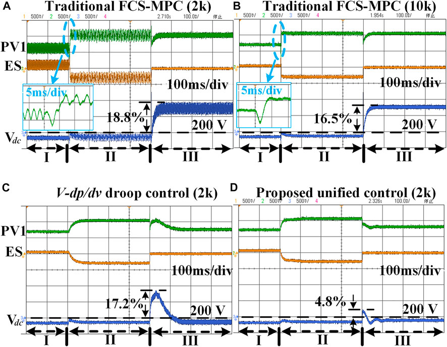
FIGURE 10. Comparisons of the MPPT and voltage regulation dynamic responses with different control methods for PV1. (A) Traditional MPC with a 2 kHz sampling frequency. (B) Traditional MPC with a 10 kHz sampling frequency. (C) Unified control based on
The comparison results are listed in Table 3. For the MPPT, a relatively high sampling frequency is preferred to restrain the power oscillation for the traditional MPC, which results in a heavy computation burden and a high switching frequency. The
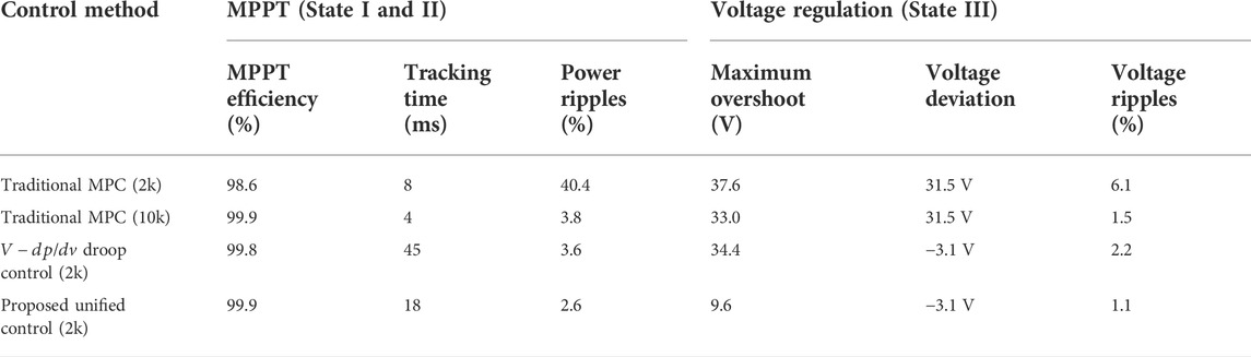
TABLE 3. MPPT and voltage regulation dynamic responses with different controls.
4.3 Robustness test
The mismatch of the predictive model can affect the performance of MPC, which may lead to an undesirable duty cycle for MPPT and voltage regulation in the PV sources. A robustness test for the proposed unified control with mismatched parameters (L and C) is shown in Figure 11. As observed, the mismatch of C has little impact on the system responses, which is actually more influenced by the mismatch of L. As shown in Eq. 5, the current prediction can be affected by the L, while the C has no influence on the current prediction. The detailed influence of the mismatched L on the MPPT and voltage regulation is shown in Figure 12. It can be seen that the voltage shows better robustness than the maximum power output, and both the maximum power output and DC-bus voltage have a better tolerance to the small-mismatched
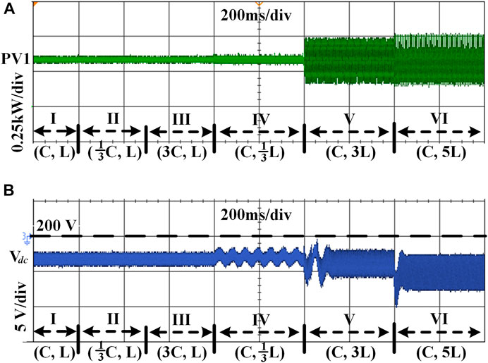
FIGURE 11. Robustness test with model parameter mismatches. (A) Power output of PV1 with mismatched C and L. (B) DC-bus voltage with mismatched C and L.
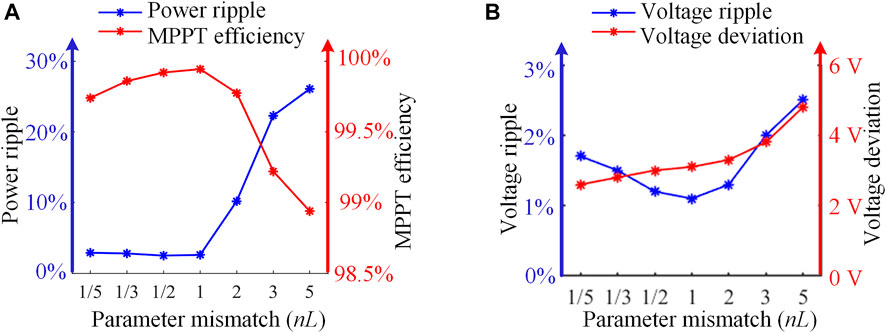
FIGURE 12. Influences of the mismatched L on the maximum power output and voltage regulation. (A) The influence on the MPPT. (B) The influence on the voltage.
5 Conclusion
In this study, a unified voltage regulation and MPPT control is designed for PV sources based on modified MPC. The PV sources can autonomously regulate the DC-bus voltage when the available maximum power is redundant or track the maximum power when their power outputs are not sufficient. The modified MPC can generate the duty cycle, which is adopted by the PV sources under constant switching frequency without a modulator. The HIL test results show that the PV sources can regulate the DC-bus voltage without ES and can proportionally share the load. In general, according to the comparison and robustness tests, the proposed unified control is suitable for PV sources without high switching frequency and can efficiently accommodate the rapidly varying illumination and load conditions. The ongoing study will further improve the credibility and reliability of the proposed control under all possible conditions, such as partial shading and bus voltage sags and surges.
Data availability statement
The original contributions presented in the study are included in the article/Supplementary Material; further inquiries can be directed to the corresponding author.
Author contributions
All authors listed have made a substantial, direct, and intellectual contribution to the work and approved it for publication.
Funding
This work is supported in part by the National Key R&D Program of China (2020YFB1506801), the Science and Technology Project of the State Grid Corporation of China (52110421005H), the National Natural Science Foundation of China (52007162 and 51877188), the Key R&D Program of Zhejiang Province (2022C01161), the China Postdoctoral Science Foundation (2022M712727), and the Fundamental Research Funds for the Central Universities (226-2022-00053).
Conflict of interest
The authors declare that the research was conducted in the absence of any commercial or financial relationships that could be construed as a potential conflict of interest.
Publisher’s note
All claims expressed in this article are solely those of the authors and do not necessarily represent those of their affiliated organizations, or those of the publisher, the editors, and the reviewers. Any product that may be evaluated in this article, or claim that may be made by its manufacturer, is not guaranteed or endorsed by the publisher.
References
Ahmad, D, Farahani, G, Vahedi, H, and Al-Haddad, K (2018). Model predictive control design for DC-DC converters applied to a photovoltaic system. Int. J. Electr. Power & Energy Syst. 103, 537–544. doi:10.1016/j.ijepes.2018.05.004
Ben-Brahim, L., Gastli, A., Trabelsi, M., Ghazi, K. A., Houchati, M., and Abu-Rub, H. (2016). Modular multilevel converter circulating current reduction using model predictive control. IEEE Trans. Ind. Electron. 63 (6), 3857–3866. doi:10.1109/tie.2016.2519320
Bollipo, R. B., Mikkili, S., and Bonthagorla, P. K. (2020). Critical review on PV MPPT techniques: Classical, intelligent and optimisation. IET Renew. Power Gener. 14 (9), 1433–1452. doi:10.1049/iet-rpg.2019.1163
Cai, H., Xiang, J., Wei, W., and Chen, M. Z. Q. (2018). Droop control for PV sources in DC microgrids. IEEE Trans. Power Electron. 33 (9), 7708–7720. doi:10.1109/tpel.2017.2771803
Cai, H., Xiang, J., and Wei, W. (2018). Decentralized coordination control of multiple photovoltaic sources for DC-bus voltage regulating and power Sharing. IEEE Trans. Ind. Electron. 65 (7), 5601–5610. doi:10.1109/tie.2017.2779412
Ding, T., Li, C., Yang, Y., Jiang, J., Bie, Z., and Blaabjerg, F. (2017). A two-stage robust optimization for centralized-optimal dispatch of photovoltaic inverters in active distribution networks. IEEE Trans. Sustain. Energy 8 (2), 744–754. doi:10.1109/tste.2016.2605926
Dragičević, T., Lu, X., Vasquez, J. C., Guerrero, J. M., and Dc Microgrids—Part, I. (2016). A review of control Strategies and stabilization techniques. IEEE Trans. Power Electron. 31 (7), 4876–4891. doi:10.1109/TPEL.2015.2478859
Dragičević, T. (2018). Model predictive control of power converters for robust and fast operation of AC microgrids. IEEE Trans. Power Electron. 33 (7), 6304–6317. doi:10.1109/tpel.2017.2744986
Errouissi, R., Al-Durra, A., and Muyeen, S. M. (2016). A robust continuous-time MPC of a DC–DC boost converter interfaced with a grid-connected photovoltaic system. IEEE J. Photovolt. 6 (6), 1619–1629. doi:10.1109/jphotov.2016.2598271
Errouissi, R., Muyeen, S. M., Al-Durra, A., and Leng, S. (2016). Experimental validation of a robust continuous nonlinear model predictive control based grid-interlinked photovoltaic inverter. IEEE Trans. Ind. Electron. 63 (7), 4495–4505. doi:10.1109/tie.2015.2508920
Ghosh, S., Rahman, S., and Pipattanasomporn, M. (2017). Distribution voltage regulation through active power curtailment with PV inverters and solar generation forecasts. IEEE Trans. Sustain. Energy 8 (1), 13–22. doi:10.1109/tste.2016.2577559
Hu, J, Shan, Y, Guerrero, J M., Adrian, I, Chan, K W, and Rodriguez, J (2021). Model predictive control of microgrids – an overview. Renew. Sustain. Energy Rev. 136, 110422. doi:10.1016/j.rser.2020.110422
Hu, J., Li, Y., and Zhu, J. (2019). Multi-objective model predictive control of doubly-fed induction generators for wind energy conversion. IET Gener. Transm. &. Distrib. 13, 21–29. doi:10.1049/iet-gtd.2018.5172
JacksonJusto, J, Mwasilu, F, Lee, J, and Jung, J-W (2013). AC-microgrids versus DC-microgrids with distributed energy resources: A review. Renew. Sustain. Energy Rev. 24, 387–405. doi:10.1016/j.rser.2013.03.067
Kumar, D., Zare, F., and Ghosh, A. (2017). DC microgrid Technology: System Architectures, AC grid interfaces, grounding schemes, power quality, communication networks, applications, and standardizations aspects. IEEE Access 5, 12230–12256. doi:10.1109/access.2017.2705914
Lashab, A., Sera, D., and Guerrero, J. M. (2019). A dual-discrete model predictive control-based MPPT for PV systems. IEEE Trans. Power Electron. 34 (10), 9686–9697. doi:10.1109/tpel.2019.2892809
Lashab, A., Sera, D., Guerrero, J. M., Mathe, L., and Bouzid, A. (2018). Discrete model-predictive-control-based maximum power point tracking for PV systems: Overview and evaluation. IEEE Trans. Power Electron. 33 (8), 7273–7287. doi:10.1109/tpel.2017.2764321
Liu, H., Loh, P. C., Wang, X., Yang, Y., Wang, W., and Xu, D. (2016). Droop control with improved disturbance adaption for a PV system with two power conversion stages. IEEE Trans. Ind. Electron. 63 (10), 6073–6085. doi:10.1109/tie.2016.2580525
Mahmood, H., Michaelson, D., and Jiang, J. (2015). Strategies for independent deployment and autonomous control of PV and battery units in islanded microgrids. IEEE J. Emerg. Sel. Top. Power Electron. 3 (3), 742–755. doi:10.1109/jestpe.2015.2413756
Meng, L., Shafiee, Q., Trecate, G. F., Karimi, H., Fulwani, D., Lu, X., et al. . (2017). Review on control of DC microgrids and multiple microgrid clusters. IEEE J. Emerg. Sel. Top. Power Electron. 5 (3), 928–948.
Nguyen, Q., Padullaparti, H. V., Lao, K., Santoso, S., Ke, X., and Samaan, N. (2019). Exact optimal power dispatch in unbalanced distribution systems with high PV penetration. IEEE Trans. Power Syst. 34 (1), 718–728. doi:10.1109/tpwrs.2018.2869195
Quevedo, D. E., Aguilera, R. P., Perez, M. A., Cortes, P., and Lizana, R. (2012). Model predictive control of an AFE rectifier with dynamic references. IEEE Trans. Power Electron. 27 (7), 3128–3136. doi:10.1109/tpel.2011.2179672
Shadmand, M. B., Balog, R. S., and Abu-Rub, H. (2014). Model predictive control of PV sources in a smart DC distribution system: Maximum power point tracking and droop control. IEEE Trans. Energy Convers. 29 (4), 913–921. doi:10.1109/tec.2014.2362934
Tonkoski, R, and Lopes, L A. C. (2011). Impact of active power curtailment on overvoltage prevention and energy production of PV inverters connected to low voltage residential feeders. Renew. Energy 36, 3566–3574. doi:10.1016/j.renene.2011.05.031
Ullah, S., Haidar, A. M. A., Hoole, P., Zen, H., and Ahfock, T. (2020). The current state of Distributed Renewable Generation, challenges of interconnection and opportunities for energy conversion based DC microgrids. J. Clean. Prod. 273, 122777. doi:10.1016/j.jclepro.2020.122777
Vicente, E. M., Vicente, P. D. S., Moreno, R. L., and Ribeiro, E. R. (2020). High-efficiency MPPT method based on irradiance and temperature measurements. IET Renew. Power Gener. 14 (6), 986–995. doi:10.1049/iet-rpg.2019.0849
Villalva, M. G., Gazoli, J. R., and Filho, E. R. (2009). Comprehensive approach to modeling and simulation of photovoltaic arrays. IEEE Trans. Power Electron. 24 (5), 1198–1208. doi:10.1109/tpel.2009.2013862
Wandhare, R. G., and Agarwal, V. (2011), “Advance control scheme and operating modes for large capacity centralised PV-grid systems to overcome penetration issues,” in 2011 37th IEEE Photovoltaic Specialists Conference, 19-24 June 2011, Seattle, WA, USA, 2466–2471. doi:10.1109/PVSC.2011.6186445
Keywords: DC microgrid, maximum power point tracking (MPPT), model predictive control (MPC), photovoltaic (PV) sources, voltage regulation
Citation: Yang P, Peng Y, Xia Y, Wei W, Yu M and Feng Q (2022) A unified bus voltage regulation and MPPT control for multiple PV sources based on modified MPC in the DC microgrid. Front. Energy Res. 10:1010425. doi: 10.3389/fenrg.2022.1010425
Received: 03 August 2022; Accepted: 25 August 2022;
Published: 13 September 2022.
Edited by:
Peng Li, Tianjin University, ChinaCopyright © 2022 Yang, Peng, Xia, Wei, Yu and Feng. This is an open-access article distributed under the terms of the Creative Commons Attribution License (CC BY). The use, distribution or reproduction in other forums is permitted, provided the original author(s) and the copyright owner(s) are credited and that the original publication in this journal is cited, in accordance with accepted academic practice. No use, distribution or reproduction is permitted which does not comply with these terms.
*Correspondence: Yonggang Peng, cGVuZ3lnQHpqdS5lZHUuY24=