 C. Nithya
 J. Preetha Roselyn
94% of researchers rate our articles as excellent or good
Learn more about the work of our research integrity team to safeguard the quality of each article we publish.
Find out more
BRIEF RESEARCH REPORT article
Front. Energy Res., 26 September 2022
Sec. Solar Energy
Volume 10 - 2022 | https://doi.org/10.3389/fenrg.2022.1009196
In a grid-connected solar photovoltaic system, voltage dips on the grid side, increased grid current, and overshoot in the inverter’s dc-link voltage are all noticed during grid disturbances. The grid code stipulates that in order to protect the cascaded power converter systems from high currents and overvoltages, the solar PV system disconnects from the grid anytime the voltage level at PCC falls below a particular standard nominal value. This study proposes combined GSC-based fault ride-through (FRT) and protection control strategies which can provide independent real and reactive power control for the inverter for effective FRT in photovoltaic parks interconnected with a large power system during grid faults. The proposed approach operates in three modes—voltage control, power factor control, and reactive power control modes. The developed protection modules in the PV system consist of over/undervoltage protection, voltage sag detection, and overcurrent detection. The inverter-fed real–reactive power control technique limits grid overcurrent by modifying active power injection into the grid and stabilizes grid voltage during faults by injecting reactive current. The performance of the proposed FRT and protection control strategy is studied through the simulation of 75 MW PV park in the EMTP platform and the experimental setup of a 5 kVA grid-connected inverter-fed solar PV system. The simulation results and hardware discussion presented in this study validate the performance of the proposed FRT scheme in comparison with conventional control schemes during grid faults.
A large power system with photovoltaic park integration is increasingly significant due to its influence on the transient behavior of the power system. The failure to conduct proper interconnection studies could result not only in suboptimal PV designs and operations but also in a severe power system malfunction. In most cases, manufacturer-specific PV modules are preferred for interconnection and to perform the primary grid integration studies before the actual design of the PV park is developed. Researchers will be able to accurately identify PV grid integration problems and suggest essential remedies with the aid of accurate generic PV park models. The inverters and the park’s control systems incorporate the appropriate nonlinearities, transients, and protective mechanisms to replicate the park’s precise transient response to external power system disturbances. The components of the solar PV system model include the park transformer, collector grid, power plant controller, converter, step-up transformer, and PV cells. The phase-locked loop, measurement sampling, filtering, regulatory loops, and protection are all included in a detailed model of the converter control. The DQ0 reference frame regulates the active and reactive power, enabling decoupled control of active and reactive power.
Many recent studies are focusing on the development of control and protective circuits for the efficient performance of the renewable integrated grid. The FRT controls can be based on hardware-based or soft solution-based techniques. The conventional hardware-based FRT controls include DC chopper, series dynamic braking resistor, crowbar circuit, and fault current limiter. These hardware-based FRT controls lack independent real and reactive power control and are not the economic solution. Hence, many intelligent inverted-based FRT controls are proposed in the literature. Muhammed et al. (Talha et al., 2020) proposed a control strategy by providing reactive power injection during voltage sags. The proposed system consists of decoupled power control, LVRT operation based on inverter specifications, and grid codes. The power imbalance between the faulty grid and the renewables is addressed in the study by He et al. (2020) in which control strategies are developed to achieve stable current and maximize energy harvesting. Abbas et al. (Komijani et al., 2022) investigated FRT in meshed microgrid systems with PV and wind systems considering voltage drop and power fluctuations. An overview of inverter control strategies with different inverters and current injection techniques is studied in the study by Hassana et al. (2020) in which the system under grid faults and equipment failure is addressed. Feng et al. (Zheng et al., 2019) discussed the hybrid control algorithm, model predictive control to suppress the grid overcurrent, and the non-MPPT algorithm is developed to limit dc link overvoltage.
Shuai et al. (Yuanabao et al., 2022) investigated the short circuit characteristics of solar PV systems with FRT capability under different voltage dips in large-scale PV plants. An extended Kalman filter-based FRT control strategy is provided in the study by Srinivas et al. (2019) without compromising power quality considering nonlinear loads. Yajing et al. (Zhang et al., 2020) discussed sliding mode-based feedback linearization to improvise the PV system response to enhance the FRT capability of the system. The control of DGs under voltage sags using constant voltage control, positive sequence control to achieve FRT capability satisfying the grid code, is discussed in the study by Rolán et al. (2022). The grid integration of renewable energy sources is regulated by a variety of standards, in order to patch PV with the utility grid and provide ancillary regulations. To avoid adverse effects on other grid-connected equipment, the total harmonic distortion for the grid voltage should not exceed 5%. According to the grid code in the study by Rolán et al. (2022), the injected reactive current is zero if the voltage dip exceeds 0.9 pu. A linear equation is used to calculate the injected reactive current if it is in the range of 0.5 and 0.9. According to the grid code, the injected reactive current is 1 pu if the grid voltage dip is greater than 0.9 pu. An intelligent fuzzy-based FRT control along with hybrid combinations of DC chopper and braking resistor is proposed in the study by Preetha Roselyn et al. (2020) to regulate the system parameters during grid faults. Mojtaba et al. (Nasiri et al., 2021) proposed the derivation of PV inverter current to enhance FRT capability through negative sequence current. A fault tolerant control to achieve voltage regulation and harmonic elimination in solar PV and the battery-integrated microgrid system is developed in the study by Liu et al. (2020) which enhances the reliability of the system under PV failures and grid failures. Ehsan et al. (Afshari et al., 2017) discussed a control strategy to reduce the grid frequency oscillations in active power and dc link voltage. The FRT strategy suited for smart transformers in a grid forming and grid following type in distribution grids to enhance the stability of the system is discussed in the study by Carlos Moreira and Lopes (2020). In order to achieve the LVRT capability of the grid-connected PV system, the active and reactive power control combined with dynamic voltage support is discussed in the study by Khan et al. (2021). In the study by Khan et al. (2022), during the normal condition, the system operates under the MPPT mode and switches to the short circuit mode during faults. In the study by Cintuglu and Ishchenko (2022), the algorithm injects a positive sequence current for regulating the PCC voltage and injects negative sequence current for mitigating the unbalanced voltage.
The contributions of this work are as follows:
• Development of a real and reactive power-based FRT control mode in the grid-side inverter to regulate the system parameters under grid faults.
• The system is operated under voltage/power factor control modes to calculate reference currents under normal conditions.
• Investigation of protection circuits, namely, over/undervoltage protection, voltage sag detection, dc chopper, and overcurrent detection, in the grid-connected PV system.
• The proposed FRT control and protective strategy is implemented and tested in the 120 kV, 60 Hz grid-tied inverter-fed solar PV system.
The study is organized as follows: Section 2 provides proposed control strategies under normal and fault conditions. The real–reactive based FRT control and protection in the solar PV park is discussed in Section 2.2. Section 2.3 discusses protective strategies for solar PV systems comprising of voltage and current protection modules. The results and discussion are provided in Section 3. Section 4 concludes the study and proposes future scope.
In this study, real–reactive based FRT control is developed and tested in a 75 MW solar PV farm and experimental setup of a 5 kVA grid-tied solar PV system. The active power generated by the solar PV system depends on weather conditions like irradiance and temperature. As per the standards of grid code compliance, the PV farm has Q control on the inverter side to control the real and reactive powers of the system. The real–reactive FRT controller is developed and tested in an inverter fed PV system integrated with the utility grid. A three-level neutral point connection voltage source inverter is used as a grid-side converter between the PV system and the grid which operates in the voltage reference frame. The DC chopper is included in the circuit for dc bus voltage protection. The line inductor and harmonic filter are connected in the GSC to improve the power quality of the system. The vector control method is developed to decouple control of real and reactive powers. The abc frame is converted into a rotating dq reference frame in which the d-component represents real power and the q-component represents reactive power. In the proposed control scheme, idg is used to the control dc link voltage and iqg is used to control the PCC voltage.
The proposed GSC-based FRT control strategy is implemented in the inverter-fed grid-tied solar PV system as shown in Figure 1. The inverter control has two levels of control consisting of outer voltage control and inner PI-based reactive power control in which the outer loop is used to calculate reference currents and inner control is used to calculate the ac reference voltage which generates the modulated switching pulses for GSC. The pulses are generated by comparing the voltage reference with a triangular carrier wave. The reactive power reference for inner PI reactive power control is generated by either outer voltage control or power factor control till outer Qcontrol is selected. Under normal conditions, the system operates in the voltage control mode in which Qref is calculated by outer P-based voltage control.
where
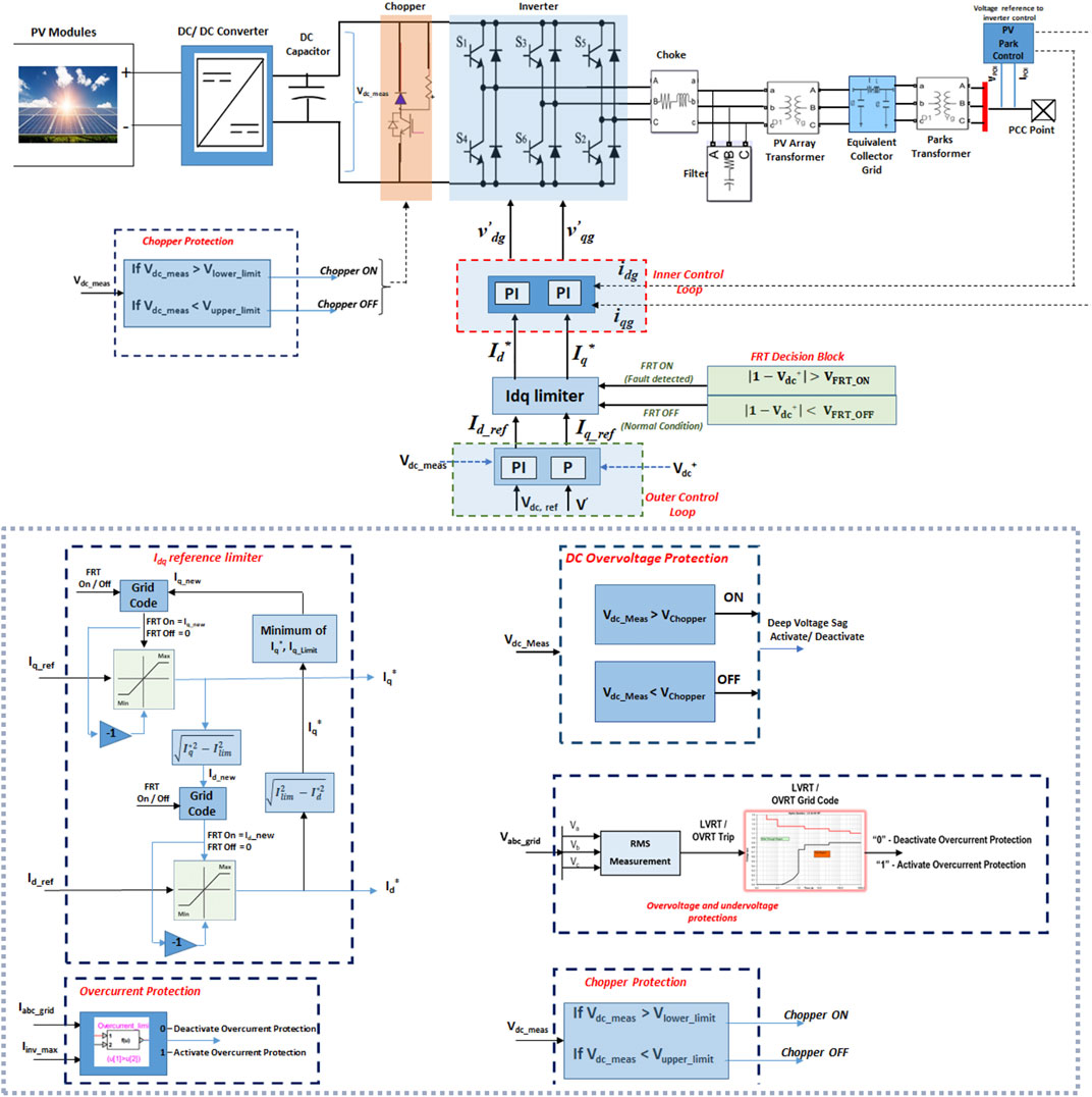
FIGURE 1. Real–reactive FRT control in inverter-fed solar PV farm.
When the solar PV system is operated under the power factor control mode, Qref is calculated using active power at PCC and desired power factor. When the system is subjected to faults at PCC, the system experiences severe voltage sag, and the Q control mode is activated in which the PI regulator output is constant by blocking the input to avoid overvoltage during faults. The measurement system acquires the voltage and current at PCC, and calculates the active and reactive powers. The protection block in the PV system consists of over/undervoltage relay circuits, voltage sag detector, DC chopper, and overcurrent detection circuit. The q-axis current is obtained using the P-based voltage control as follows:
where
As shown in Figure 1, the inner control loop employs a cross-coupling method and feed-forward controller to achieve safe operating currents from the inverter. To keep the inverter current within acceptable limits, a double loop feed-forward control method based on a proportional integral controller is designed. A decoupling method is utilized to generate reference voltages in the dq reference frame by separating active and reactive currents (Preetha Roselyn et al., 2020).
The voltage at the PCC point of a PV system is calculated as follows:
where
where kp and ki are PI parameters of the inner current control loop; Vd_choke and Vq_choke are the voltages across the choke filter of the grid-side converter in the dq frame.
Under normal conditions, the system operates under the voltage control mode in which active current is given priority in the grid-tied PV system.
where Id_limit, Iq_limit, and Ilim are d-axis, q-axis, and grid-side inverter current limits, respectively. The system switches to the FRT mode during grid faults, satisfying grid code standards. The voltage sag detector circuit activates the FRT mode based on the FRT decision logic as follows:
Once the FRT mode is activated, the GSC control prioritizes reactive current as follows:
The protection system in the grid-tied PV inverter system consists of overvoltage and undervoltage protection relays, DC chopper-based overvoltage protection, and overcurrent detection circuit. As indicated in Figure 1, DC overvoltage protection is engaged when dc voltage exceeds the dc link reference voltage and deactivated when the dc voltage drops below the threshold. The instantaneous overvoltage protection depends on the instantaneous peak value and cumulative duration. The RMS-based overvoltage protection is based on the LVRT requirement in which the proposed model senses the RMS voltage and sends the trip signal to the inverter. The overcurrent protection circuit protects the converter from overcurrent when the current exceeds the threshold value.
The proposed method of FRT control is implemented in a 120kV, 60 Hz grid-tied inverter fed solar PV system. The utility grid is connected in bus 2 and 30 MW, and 15 MVAR loads are connected in the fifth and sixth buses in the test system. The system has 5 transmission lines which are represented as equivalent impedances connected between buses and the ground. The value of the inductor and capacitor on the grid side are 0.3831 mH and 7 µF, respectively.
The proposed FRT and protection-based control strategies are implemented in a 5 kVA utility grid-integrated solar PV system, as shown in Figure 2, which consists of a PV panel, boost converter, grid-tied inverter, FPGA Spartan-6 processor, grid measuring system, and isolation transformer. The grid faults are realized by creating a dip in grid voltage using an isolation transformer. The developed control strategies are deployed in the FPGA processor, and the measurements on the grid side and PV side are acquired using the grid-measurement module.
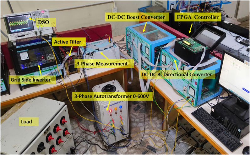
FIGURE 2. Experimental setup of 5 kVA grid-integrated solar PV.
The proposed inverter control and protection system comprising of inner and outer control loops are developed and implemented in the 6-bus test system integrated with the utility grid. In addition to control modes, developed protection circuits are over/undervoltage relays, voltage-sag detection, DC chopper control, and overcurrent detection. To verify the effectiveness of the proposed control strategies, the detailed simulation model is simulated in EMTP version 4.1.3 simulation environment. From t = 0–0.2 s, normal operation, and t = 0.2–0.4 s, FRT operation is enabled and the fault is cleared at 0.4 s in the test system. When the PCC voltage is between 75–88 kV, the FRT mode is activated, and when it drops below 75 kV, solar PV must be disconnected from the grid. The performance of the system under fault conditions without a controller is shown in Figure 3A in which grid voltage reduces to 19 kV, grid current overshoots to 4 kA, real power transfer is zero, and dc link voltage is increased to 1600 V.
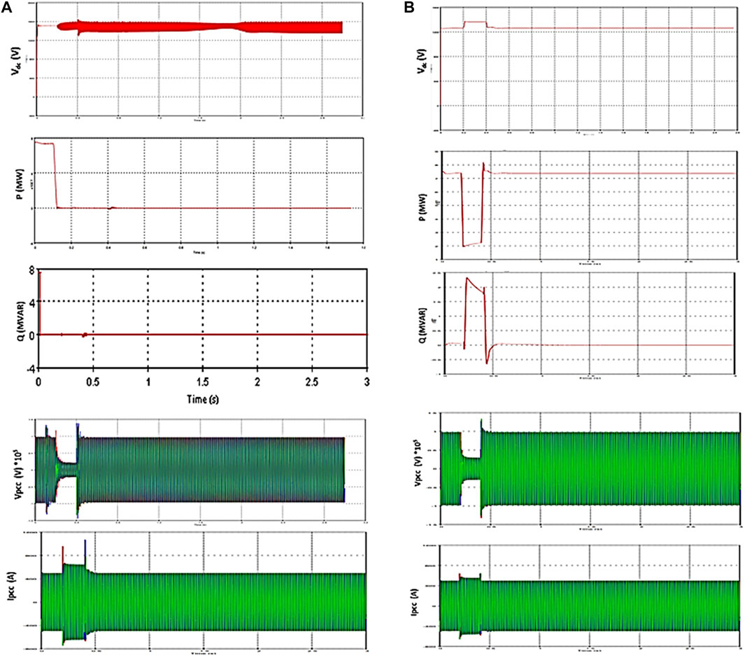
FIGURE 3. Performance of system during grid faults: (A) without control and (B) proposed control.
The response for a balanced 3 phase voltage sag of 25% is tested for 200 ms duration of 0.2–0.4 s after the implementation of proposed FRT and protection is provided in Figure 3B. The performance of proposed GSC-based control strategies regulates the grid voltage drop which reduces from 21% to 31% of the nominal value.
The overcurrent reduces to 600 A, which achieves 20% improvement using the proposed system. This results in reduced power injection from the solar PV system due to the injection of reactive power into the grid. The dc link voltage is also reduced from 1600 to 1300 V. As the voltage sag is compensated by the injection of reactive power by proposed GSC-based control strategies, the active power is reduced from 75 to 24 MW.
The proposed FRT and protection-based control strategies during fault conditions are implemented in the 5 kVA grid-connected solar PV experimental setup. The hardware setup is deployed with proposed control strategies and is tested under low voltage conditions on the grid side which is realized as grid faults. The low voltage is provided on the grid side using the isolation transformer by reducing the voltage at the PCC end by 30% which leads to a 20% increase in grid current. The real power and the reactive power have reached zero and have higher power oscillations in the system parameters. Upon the implementation of proposed control algorithms during grid faults, the system is more enhanced with FRT and protection control strategies as shown in Figure 4. The grid-tied inverter-fed PV experimental setup injects suitable reactive power by reducing the real power, which thereby meets the local loads and ensures grid stability instead of zero power injection in the absence of controllers. The grid voltage is increased by 30%, which has mitigated the sag condition during grid faults, and the overcurrent in the grid side is also reduced by 20%. The real power injection is 465 W and the reactive power support is 320VAR. This enhanced FRT and protection-based control algorithm have greatly supported the grid by ensuring stability and reliability even during grid faults without any disconnection of the solar PV system satisfying the grid code requirements. This system also protects the converter circuits from high dc link voltage and overcurrent in the ac side.
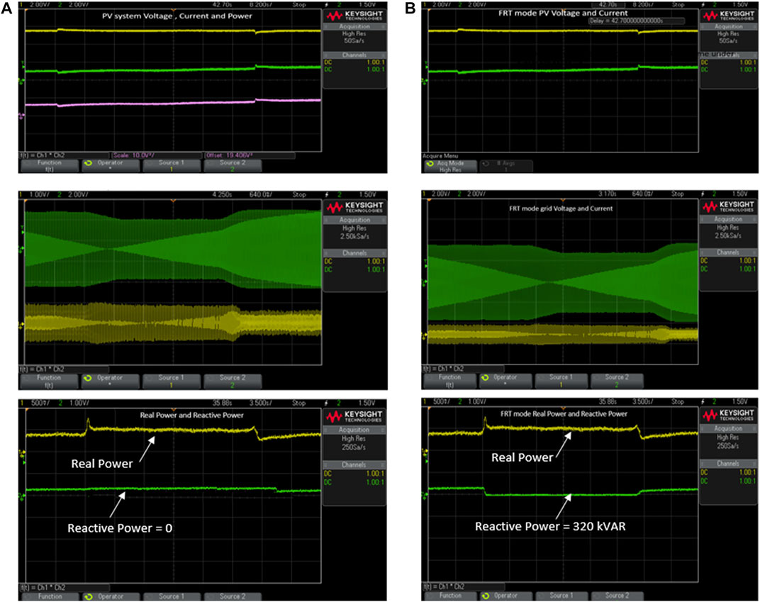
FIGURE 4. System parameters during grid faults in the 5 kVA grid-tied solar PV experimental setup: (A) without control and (B) with proposed FRT control.
The system is further studied in the experimental setup upon the implementation of proposed protection modules in the grid-tied solar PV system in which during severe grid faults at which the grid code standards beyond the FRT region cannot be satisfied, then as per the grid code compliance, the solar PV system is disconnected from the grid to safeguard the power converters in the solar side. This allows the working of the proposed protection modules which trips the overcurrent relay in the experimental setup when high sag of greater than 40% is created in the grid-side isolation transformer and the settings of the protection module. The solar PV system when disconnected from the grid feeds the local loads and satisfies the local loads. The proposed system provides promising results in both the 6-bus power network in simulation and the 5 kVA grid-tied solar PV experimental setup.
This study presents the discussion on the implementation of combined GSC-based FRT and protection control strategies in the 75 MW solar PV park farm and 5 kVA grid-integrated solar hardware setup. The modes of operation under different system conditions are validated and tested using the test models. The developed protection modules in the PV system consisting of over/undervoltage protection, voltage sag detection, and overcurrent detection are implemented. The proposed FRT control strategy during grid faults improves the system by independent control of real and reactive powers. The reactive power is injected by reducing the real power transfer by controlling currents in the inverter. The grid-tied PV system is enhanced by the reduction in grid overcurrent and voltage sag mitigation on the grid side which ensures grid stability even during grid faults. The dc link voltage is greatly reduced, which protects the power converter circuits and makes the system stay connected during fault conditions and support the grid. The proposed system provides better results than other FRT schemes in the literature, which validates the system enhancement using the proposed controllers. This study can be extended by studying the transient stability of the solar-fed power system using proposed control algorithms.
The original contributions presented in the study are included in the article/Supplementary Material; further inquiries can be directed to the corresponding author.
CN: conceptualization, methodology, software, formal analysis, and writing. JR: conceptualization, formal analysis, and writing.
The authors acknowledge the Department of Electrical and Electronics Engineering of SRM Institute of Science and Technology, Kattankulathur, for their support.
The authors declare that the research was conducted in the absence of any commercial or financial relationships that could be construed as a potential conflict of interest.
All claims expressed in this article are solely those of the authors and do not necessarily represent those of their affiliated organizations, or those of the publisher, the editors, and the reviewers. Any product that may be evaluated in this article, or claim that may be made by its manufacturer, is not guaranteed or endorsed by the publisher.
The Supplementary Material for this article can be found online at: https://www.frontiersin.org/articles/10.3389/fenrg.2022.1009196/full#supplementary-material
Afshari, E., Moradi, G. R., Rahimi, R., Farhangi, B., Yang, Y., Blaabjerg, F., et al. (2017). Control strategy for three-phase grid-connected PV inverters enabling current limitation under unbalanced faults. IEEE Trans. Ind. Electron. 64 (11), 8908–8918, Nov. doi:10.1109/TIE.2017.2733481
Carlos Moreira, J., and Lopes, J. P. (2020). Fault-ride-through strategies for grid-tied and grid-forming smart-transformers suited for islanding and interconnected operation. Electr. Power Syst. Res. 189, 106616.
Cintuglu, M., and Ishchenko, D. (2022). Multiagent-based dynamic voltage support of power converters during fault ride-through. IEEE J. Emerg. Sel. Top. Ind. Electron. 3 (3), 549–558. doi:10.1109/JESTIE.2021.3119998
Hassana, Z., Amira, A., Selvaraja, J., and Rahimab, N. A. (2020). A review on current injection techniques for low-voltage ride-through and grid fault conditions in grid-connected photovoltaic system. Sol. Energy 207, 851–873.
He, Y., Wang, M., and Xu, Z. (2020). Coordinative low-voltage-ride-through control for the wind-photovoltaic hybrid generation system. IEEE J. Emerg. Sel. Top. Power Electron. 8 (2), 1503–1514. doi:10.1109/JESTPE.2019.2958213
Khan, M. A., Haque, A., and Kurukuru, V. S. B. (2021). Dynamic voltage support for low-voltage ride- through operation in single-phase grid-connected photovoltaic systems. IEEE Trans. Power Electron. 36 (10), 12102–12111. doi:10.1109/TPEL.2021.3073589
Khan, M. A., Haque, A., Kurukuru, V. S. B., and Mekhilef, S. (2022). Advanced control strategy with voltage sag classification for single-phase grid-connected photovoltaic system. IEEE J. Emerg. Sel. Top. Ind. Electron. 3 (2), 258–269. doi:10.1109/JESTIE.2020.3041704
Komijani, A., Sedighizadeh, M., and Kheradmandi, M. (2022). Improving Fault Ride-through in meshed microgrids with wind and PV by virtual synchronous generator with SFCL and SMES. J. Energy Storage 50, 103952.
Liu, Z., Lu, Y., Kong, J., Gong, J., and Wang, S. (2020). Multimodal fault-tolerant control for single-phase cascaded off-grid PV-storage system with PV failure using hybrid modulation. Microelectron. Reliab. 114, 113772.
Nasiri, M., Arzani, A., and Guerrero, J. M. (2021). LVRT operation enhancement of single-stage photovoltaic power plants: An analytical approach. IEEE Trans. Smart Grid 12 (6), 5020–5029. doi:10.1109/TSG.2021.3108391
Preetha Roselyn, J., Pranav Chandran, C., Nithya, C., Devaraj, D., Venkatesan, R., Gopal, V., et al. (2020). Design and implementation of fuzzy logic based modified real-reactive power control of inverter for low voltage ride through enhancement in grid connected solar PV system. Control Eng. Pract. 101, 104494. doi:10.1016/j.conengprac.2020.104494
Rolán, A., Bogarra, S., and Bakkar, M. (2022). Integration of distributed energy resources to unbalanced grids under voltage sags with grid code compliance. IEEE Trans. Smart Grid 13 (1), 355–366. doi:10.1109/TSG.2021.3107984
Srinivas, V. R., Singh, B., and Mishra, S. (2019). Fault Ride-through strategy for two-stage grid-connected photovoltaic system enabling load compensation capabilities. IEEE Trans. Industrial Electron. 66, 11.
Talha, Muhammad, Raihan, S. R. S., and Abd Rahim, N. (2020). PV inverter with decoupled active and reactive power control to mitigate grid faults. Renew. Energy 162, 877–892.
Yuanabao, S., Yang, F., Jian, C., and Zhanga, Y. (2022). Experimental study on short-circuit current characteristics of a photovoltaic system with low voltage ride through capability under a symmetrical fault. Energy Rep. 8, 4502–4511.
Zhang, Y., Wang, J., Li, H., Zheng, T. Q., Lai, J. S., Li, J., et al. (2020). Dynamic performance improving sliding-mode control-based feedback linearization for PV system under LVRT condition. IEEE Trans. Power Electron. 35, 11745–11757.
Keywords: grid-connected solar PV, fault ride through, reactive power injection, real–reactive power control, protection module
Citation: Nithya C and Roselyn JP (2022) Development of grid-side converter-based FRT control and protection in a grid-connected solar photovoltaic park system under different control modes. Front. Energy Res. 10:1009196. doi: 10.3389/fenrg.2022.1009196
Received: 01 August 2022; Accepted: 25 August 2022;
Published: 26 September 2022.
Edited by:
Inderjeet Singh, New York University Abu Dhabi, United Arab EmiratesReviewed by:
Mohammed Ali Khan, Brno University of Technology, CzechiaCopyright © 2022 Nithya and Roselyn. This is an open-access article distributed under the terms of the Creative Commons Attribution License (CC BY). The use, distribution or reproduction in other forums is permitted, provided the original author(s) and the copyright owner(s) are credited and that the original publication in this journal is cited, in accordance with accepted academic practice. No use, distribution or reproduction is permitted which does not comply with these terms.
*Correspondence: J. Preetha Roselyn, cHJlZXRoYS5yb3NlbHluQGdtYWlsLmNvbQ==
Disclaimer: All claims expressed in this article are solely those of the authors and do not necessarily represent those of their affiliated organizations, or those of the publisher, the editors and the reviewers. Any product that may be evaluated in this article or claim that may be made by its manufacturer is not guaranteed or endorsed by the publisher.
Research integrity at Frontiers
Learn more about the work of our research integrity team to safeguard the quality of each article we publish.