 Yue Li1
 Pengcheng Yang
 Yonggang Peng
 Yanghong Xia
- 1College of Electrical Engineering, Zhejiang University, Hangzhou, China
- 2Xiaoshan Power Supply Bureau, Hangzhou, China
Due to the advantages of effectively integrating diversified loads and renewable sources, hybrid DC/AC microgrids have attracted the common attention of industry and academia. Meanwhile, with the increasing number of power electronic devices connected to the system, the complexity of the system increases, which puts forward higher requirements for galvanic isolation and intelligent control methods. This study proposes a unified decentralized framework for isolated interlinking converters (IICs) in hybrid DC/AC microgrids, which include topology and a control strategy to solve the aforementioned problems. Firstly, in terms of topology, a dual active bridge (DAB) converter is adopted to realize galvanic isolation and DC voltage conversion, which can facilitate the interconnection of DC microgrids or be combined with VSC for the interconnection of DC and AC microgrids. Secondly, in terms of the control strategy, a bidirectional voltage–supporting control strategy is proposed for IICs, in which the frequency and voltage are adopted as the indications to balance the power and strengthen the inertia interaction of microgrids. Furthermore, with the proposed control strategy, the voltage sources of different microgrids can share the power fluctuation, cooperatively. The stability of the proposed strategy is analyzed, and the effectiveness is verified by several HIL experiments.
1 Introduction
With the increasing awareness of environmental protection and public’s expectation of opportunities brought by energy industry upgrade, the transformation of the energy structure of power systems has been widely concerned and promoted. The microgrid framework has been regarded as cost-effective power system architecture due to the advantages of high flexibility and easy integration of multiple types of renewable sources and loads.
Microgrids can be divided into three categories according to their components: DC microgrids (Dragičević et al., 2016a; Dragičević et al., 2016b), AC microgrids (Begum et al., 2017; Semënov et al., 2017), and hybrid DC/AC microgrids (Nejabatkhah and Li, 2015; Ansari et al., 2021). Similar to conventional AC utility systems, renewable energy sources and loads of all types are connected to AC buses either directly or through converters. Because of its good compatibility with the conventional utility grid, the AC microgrid has been researched deeply in the early stage. However, a large number of renewable power generation devices such as photovoltaic and energy storage, as well as loads such as electric vehicles, exhibit natural DC output characteristics. If these DC sources and DC loads connect to the AC microgrid, the DC/AC conversion stage is introduced, which decreases power efficiency. With the development of power electronic device integration techniques and design methods, DC voltage conversion and its interconnection with AC utility have a breakthrough solution. Thus, the DC microgrid has ushered in a massive development because of its advantages on high efficiency without harmonic and reactive power transmission problems. To effectively utilize the benefits of the two types of microgrids, the hybrid DC/AC microgrid emerges as the times require. While integrating various kinds of renewable energy sources and loads, the hybrid DC/AC microgrid can also ensure interaction with the utility grid.
With the increase of renewable energy sources and integration of various loads in the hybrid DC/AC microgrids, the power absorption capacity of the microgrids and smooth operation ability face enormous challenges. The structure and control method of IIC play a vital role in the stability and smooth operation of the hybrid microgrid. From the perspective of the device structure, single-stage conversion topology is commonly adopted in the early hybrid DC/AC microgrids. However, with the extensive integration of renewable generation equipment and diversified loads, single-stage equipment cannot meet the higher needs of control operations. On the one hand, the direct connection between the AC and the DC microgrids using a single-stage converter may introduce a circulating current, which requires an additional suppression strategy (Xia et al., 2018; Xia et al., 2020). On the other hand, the standard of the DC voltage level is not mature, the renewable generations and loads have various voltage levels, and single-stage converters often have specific requirements on DC voltage according to their modulation modes. Thus, the matching of DC voltage will also cause connection problems. In view of the aforementioned issues, the structure of a two-stage converter is proposed, which can be divided into the isolated and non-isolated types. The non-isolated type usually combines a single-stage structure with a non-isolated DC voltage transformation topology such as the Buch and Boost circuit, which still faces the problem of circulating current. By contrast, the isolated two-stage converter structure adds the line frequency transformer module based on the single-stage converter structure. Thus, the topology has the dual functions of isolation and voltage matching. In reality, line frequency transformers are widely adopted because of their reliability, simplicity, and low cost. However, the drawbacks of low energy density and colossal volume occupation of line frequency transformers limit their applications in hybrid DC/AC microgrids. Compared with conventional line frequency transformers, with the development of solid-state transformers (SSTs), the DC transformers are less susceptible to DC offset and possess more controllability when employed in microgrids, with less volume occupation, voltage sag ride-through capability, and current limitation ability. Therefore, DC transformers are gaining increasing concern and promotion. Replacing conventional passive line frequency transformers with the SST-based IIC can be viewed as a potential solution for application in hybrid DC/AC microgrids.
Shamshuddin et al. (2020) have provided a complete overview of SST, such as concepts, topologies, design criteria, and control schemes. There are two different groups of power conversion stages: solid-state transformer block (SSTblock) and solid-stage transformer isolated block (SSTi-block), which can be considered as the base blocks for any SST. SSTi-block is also known as the simplest form of an SST, with a single port available at the primary and secondary sides of the medium frequency transformer (MFT), cascading with SSTblock extension stages to form various configurations of SSTs. The dual active bridge (DAB) is one type of SSTi-block based on nonresonant topology, which was introduced in 1991 for higher power density isolated DC-DC conversion. The connection interfaces of different microgrids in hybrid systems mainly include the interface structure between DC microgrids and the interface structure between the DC and AC microgrids. The connections between the different AC microgrids usually include three-stage AC-DC-AC structures, which can be regarded as the combination of the aforementioned two connection structures. Conventional DC-DC converters such as the Buck and Boost topologies are often utilized to connect different DC microgrids. Comparatively, the DAB can provide galvanic isolation and voltage recovery function under abnormal conditions. In addition, it is challenging to develop a unified topology in multi-voltage-level DC microgrids because of the voltage limitation on both sides in conventional topologies. For instance, a buck circuit is usually used for voltage reduction, while a boost circuit is generally used for voltage lifting. Therefore, when the voltage of the connected microgrid changes, it may involve the trouble of topology transformation. By contrast, the DAB topology has less constraint on both sides’ voltage and has more flexible control modes, which is more beneficial to the interconnection between the multi-voltage-level DC microgrids. In addition to DC microgrids with different voltages, various heterogeneous AC microgrids may be integrated into the hybrid system. The topology formed by the DAB and AC/DC voltage source converter (VSC) can achieve galvanic isolation and facilitate interconnecting between multiple AC and DC microgrids. Therefore, the unified interface structure of hybrid DC/AC microgrids can be built, in which the DAB serves as IIC between the DC microgrids, and the combination of DAB with VSC serves as IIC between the DC and AC microgrids. The unified structure is shown in Figure 1.
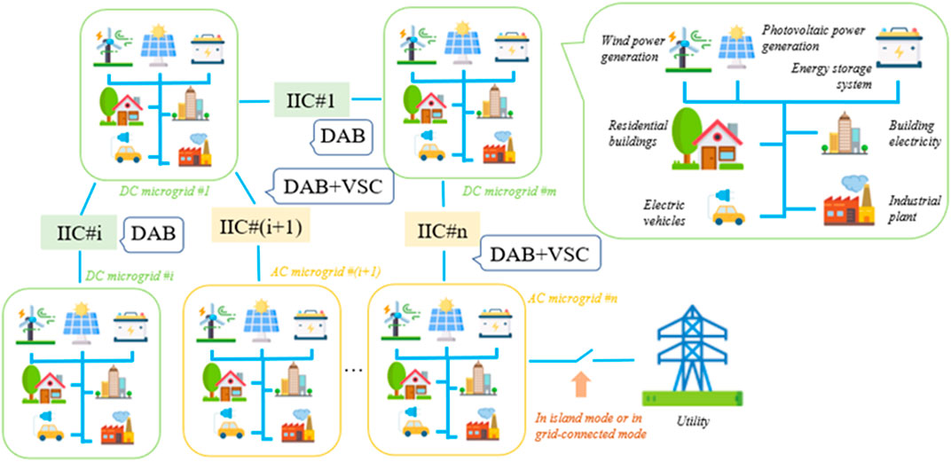
FIGURE 1. Representative hybrid DC/AC microgrids with the unified structure as the interface.
The control methods of converters in hybrid DC/AC microgrids can be classified into three categories according to their dependence on communication. A centralized control requires fast communication to get the overall system operation status (Hossain et al., 2017), which is suitable for optimal operation control and can quickly realize the unified performance of the system through fast communication. However, the centralized control is highly dependent on communication and faces challenges brought by single-point failure. Compared with the centralized control strategy, a distributed control can also realize unified performance through reduced communication requirements, which only needs the status of adjacent points through low-bandwidth communication (Espina et al., 2020; Zhang et al., 2021). The decentralized control has the lowest requirements for system communication and generally only requires obtaining the local status, which is suitable for a modular primary control (Xu et al., 2017; Yang et al., 2020). However, it is challenging to realize unified performance in a decentralized manner. Regardless of the communication requirements, most current control strategies are actually directional. For instance, the control methods for Buck or Boost topologies often assume that the voltage on one side is stable while the voltage on the other side is controlled to a preset value (Konar and Ghosh, 2015; Kumar et al., 2015). A common droop control for the VSC, such as the P-f droop control, can only realize the power support from the DC microgrid to the AC microgrid, which can be viewed as a directional control strategy (Guerrero et al., 2011; Rocabert et al., 2012). When the power imbalance occurs in the DC microgrid, it is difficult for the AC microgrid to achieve reverse power support. In this situation, the P-f droop control needs to be switched into the DC droop or DC voltage control to support the DC microgrid, thus increasing the control complexity.
Many research have focused on power management and control in hybrid DC/AC microgrids to realize a coordinated operation with or without relying on communication links. To form a modular and scalable architecture for interconnection between microgrids, various interlinking units have been proposed by researchers. Yu et al. (2020) presented a novel interlinking converter named smart interlinking unit (SIU), which could provide multiple AC/DC interfaces and diverse operation modes with various control functionalities. Furthermore, an SIU-based hybrid microgrid architecture and a hierarchical control structure were developed. According to the basic configuration of the SIU, a back-to-back (B2B) structure was formed by two VSCs, and a common DC bus was encompassed. However, this study mainly focuses on connecting two AC microgrids and the ESS microgrid at the intermediate DC bus. The proposed method for the VSC in a grid-connected mode is the unidirectional control scheme. In the work by Yu et al. (2022a), a new interlinking converter referred to as the energy networking unit (ENU) has been proposed. The ENU-based hybrid microgrid clustering architecture is established, which is characterized by scalability, reconfigurability, and modularity. A proposed decentralized control strategy for this architecture can realize autonomous power exchange between the microgrids considering the ESS restrictions and a switch to smooth mode. This study mainly focuses on the power interaction between clusters, and the adopted method for clusters belongs to a bidirectional control. Yu et al. (2022b) first introduced the pseudo hierarchical energy management architecture built upon a smart EV charging point. The DAB is the connection interface between the ESS and DC microgrids. The proposed control strategy relies on a simple communication link, and the applied method for VSC in the grid-connected mode belongs to the unidirectional control. In Eghtedarpour and Farjah (2014), Maryama et al. (2014), and Malik et al. (2018), a single-stage VSC was used to interface the DC and AC microgrids. The corresponding droop control and modified droop strategies were designed for load sharing and power interaction. While Yu et al. (2014) proposed a hierarchical power management strategy for the SST-based system, which is mainly used among the DC microgrids as a unidirectional control, Cao et al. (2018) showed that microgrids with conventional power transformers are unsuitable for smart buildings due to their uncontrollability and vulnerability to interference. Thus, the hybrid AC/DC microgrid architecture for smart buildings has been proposed to increase the penetration of DGs and isolate the interference to the grid based on a modular multilevel converter–based solid-state transformer (MMC-SST). The proposed control strategy belongs to the unidirectional control and involves the requirement of mode switching. Based on the current research foundation, a unified topology with isolation and bidirectional control strategy in the DC/AC hybrid system can be established, which is proposed and investigated in this study. Table 1 shows the comparisons of the proposed IIC with other converters and the corresponding strategies mentioned previously.
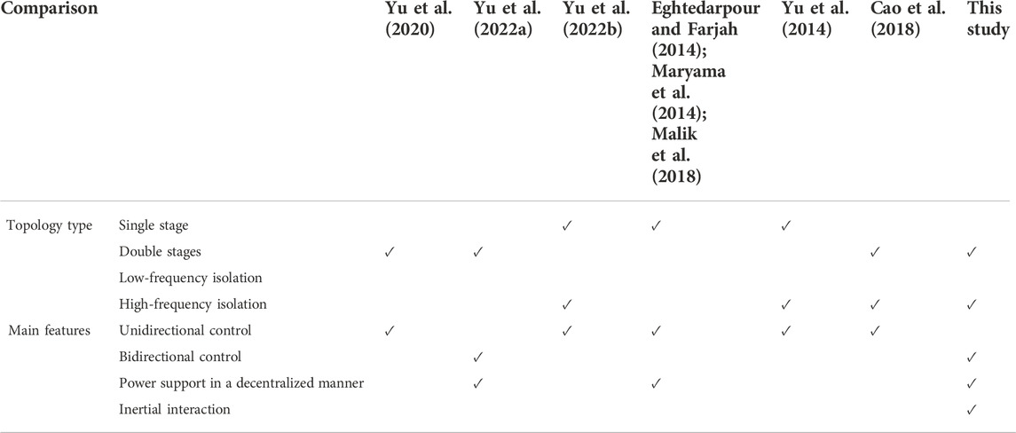
TABLE 1. Comparison with control strategies.
The main contributions of this study are as follows:
1) A unified framework for IICs is proposed to facilitate the interconnection between microgrids in hybrid DC/AC microgrids, where the DAB is adopted to realize galvanic isolation and DC voltage conversion, and the combination of DAB and VSC is adopted for the connection between the DC and AC microgrids.
2) A bidirectional voltage–supporting control strategy is proposed for IICs, where the frequency and voltage are adopted as the indications to balance the power and strengthen the inertia connection of the microgrids. Besides, the proposed control is decentralized, which can realize the power sharing between voltage sources in different microgrids of the hybrid DC/AC system.
The remaining of this article is organized as follows: Section 2 describes the unified topology of IIC in hybrid microgrids and the operation principle. Section 3 introduces the unified control framework for IIC. Section 4 verifies the stability of the proposed control strategy. This article also depicts some typical applications of hybrid DC/AC microgrids. The proposed control method is verified through hardware-in-loop (HIL) tests in Section 5, and Section 6 presents the conclusion of this study.
2 System description and operating principle
This section mainly introduces the structure of the interfacing topology of hybrid microgrids. As described in the previous section, interfaces in hybrid DC/AC microgrids include the structure connecting DC microgrids of different voltage levels and the structure connecting DC microgrid and AC microgrid. In the multi-heterogenous hybrid DC/AC microgrids, to make the connecting interface a unified topology, the DAB is adopted for multi-voltage DC microgrid connections, and the combination of DAB and VSC is adopted for DC microgrid and AC microgrid connections. In the proposed topology, the DABs exist in both the independent interface and interface connecting with the VSC, the functions of which are essentially the same. Both DABs are adopted to achieve DC voltage adaption and galvanic isolation. Meanwhile, this study aims to build a modular and unified decentralized control framework. Thus, the control of DAB in the two interfaces should be the same. Therefore, this study takes the combined topology of DAB and VSC as an example to introduce the control framework, which covers the control strategy of DAB as a separate interface.
2.1 Introduction to topology numbering guidelines
In order to introduce the control and modeling methods of the framework more conveniently and clearly in the following sections, it is necessary to design and summarize the numbering guidelines of the multi-heterogeneous microgrid system first. According to the topology shown in Figure 1, the system is composed of multiple DC and AC microgrids. First of all, assuming that there are
The power output from each DC microgrid to the corresponding DC bus is written as
2.2 Topology of IIC
As shown in Figure 2, the structure topology of
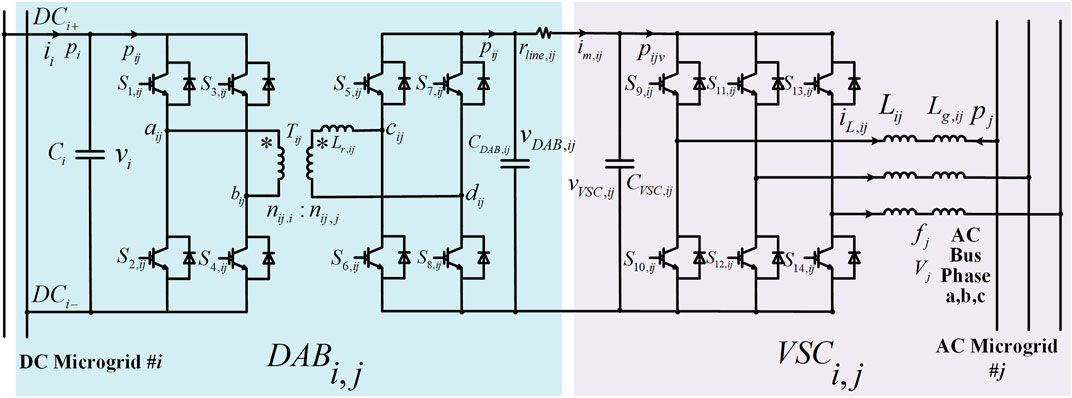
FIGURE 2. Typical topology structure of the unified interface
The entire structure is composed of two parts, each emphasizing different functions. The DAB part is mainly adopted to realize galvanic isolation and DC voltage conversion. The three-phase VSC part is adopted to connect the DC and AC microgrids. When compared to the conventional two-stage IIC, the proposed topology essentially replaces the passive line frequency transformer with a more controllable DAB structure, which achieves the galvanic isolation and voltage-matching requirements on the DC part. The advantages of the DAB, such as flexible regulation, diverse functions, and high energy density, are fully utilized.
In order to form a unified decentralized framework, in addition to the unified topology, the corresponding control strategy is also of great importance. The control strategies adopted for topologies (not only the conventional topologies such as Buck and Boost but also the SST-based isolated topologies such as DAB) to interface different DC microgrids are usually to fix the voltage on one side and adjust the voltage on the other side. This kind of control strategy is actually a directional control strategy, which presupposes that the voltage on the source side is stable. Therefore, when the source side is in a fault condition, the other side cannot adjust or support in reverse. Furthermore, the droop control is one of the common methods for VSC topology, in which a predefined frequency is changed according to the measured power value. The control mainly involves the situation where the AC side is at risk while the DC side is stable. Thus, the control method is also a directed control in nature, which means the whole system may break down if the DC microgrid is unstable.
Aiming at the aforementioned problems, it is necessary to propose a unified decentralized control framework for hybrid DC/AC microgrids. The proposed control method should be characterized by the following features: 1) the proposed control strategy should be a bidirectional control strategy, which means that the control method should emphasize the relationship between two microgrids rather than assume one is stable to adjust the other microgrid. 2) The proposed control framework should be the primary control framework, and the power levels of the adjacent microgrids should be kept as consistent as possible. These features can keep the power mutuality between heterogeneous microgrids in the hybrid system, regardless of which microgrid is in power shortage or power surplus status.
3 Unified control framework
3.1 Per unit processing of system
In general, per unit processing of the system is beneficial to the realization of the unified control framework. The normalization procedure divides the measured value by the reference value. On the one hand, the results of different systems or modules can be judged and compared intuitively after the system is standardized, which is equivalent to establishing a unified comparison benchmark. In addition, in the case of multiple voltage levels, the total impedance unit of the line is equal to the sum of all the impedance units. Thus, normalization is helpful to the superposition of impedance on different voltage levels. On the other hand, the per unit processing of the system can be adopted to generalize the control strategy, which means adapting the design of the control strategy or control parameters to different practical systems of the same model. In the multi-heterogeneous hybrid microgrids, the models of different microgrids are basically the same, but there may be significant differences in different microgrid parameters, voltage levels, and even AC microgrid frequencies. The numerical differences of variables and circuit parameters between different microgrids are greatly weakened after unit processing, which makes the control system develop a unified design method and process (Yan et al., 2020).
Without loss of generality, the IIC shown in Figure 2 is taken as an example to illustrate the per unit processing of hybrid DC/AC microgrids. For per unit processing, the selection and calculation of the reference values in hybrid microgrids are shown in Equation 1.
where
The corresponding per unit processing is given in: Eq. 2.
Through the aforementioned per unit processing, the core controller and parameters designed for the system of one voltage level can be transferred to similar systems of other voltage levels only with a bit of modification, thus saving much debugging cost. In addition, the numerical range of each variable is narrower after standard normalization, which is more convenient for the digital implementation of the controller.
3.2 Control framework of dual active bridge
DAB is adopted in IIC to realize galvanic isolation and voltage matching. Various control methods for the DAB part currently depend on different control objectives. Most control methods are limited to fixing the voltage on the primary side and controlling the voltage on the secondary side as required. These control methods are directional control methods, and when the voltage of the primary side is unstable, the secondary side cannot support the primary side in time. Therefore, it is necessary to establish a nondirectional control method that can realize bidirectional support for the DAB part.
In terms of the modulation scheme, the most commonly adopted modulation method for DAB is the single phase shift (SPS) modulation. The DAB operates at a constant frequency, and the primary and secondary sides operate at a fixed duty cycle of 50% (Mi et al., 2008; Zhao et al., 2009). The phase shift angle is the phase difference between the primary and secondary sides’ switching signals. The magnitude of the phase shift angle affects the amount of transmission power, and the leading or lagging of the phase shift angle affects the direction of the transmission power. According to Krismer and Kolar (2012), the range of the phase shift angle can be limited to the interval
where
According to Equation 4, the transmitted power variation is linearly related to the phase shift angle variation. As shown in Figure 2, two capacitors are on the primary and secondary sides. From the power perspective, the bilateral capacitors’ state–space models are as shown in Equation 5:
Small-signal models are derived from Equation 6 by linearizing and Laplace transforming of Equation 5.
where
In addition to achieving the same power level between different microgrids, converters should also take inertia support, which is one urgent problem for the smooth operation of the hybrid DC/AC microgrids. When compared with the inertia support provided by the synchronous generator in the conventional utility grid, with the increasing proportion of power electronic equipment in the modern power system, generators are gradually replaced by power converters, resulting in a lack of inertia capacity of the entire system. Thus, virtual synchronous generator (VSG) technology is proposed to make the converter mimic the characteristics of the rotating electrical machine, thereby improving the damping and inertia of the system (Fang et al., 2018). However, unlike synchronous generators, an additional energy storage system is required to cooperate with the interfacing converter since the converter itself cannot absorb or generate any kinetic energy. Therefore, the inertia and damping capabilities are essentially provided by those units that absorb and deliver energy, such as synchronous generators, energy systems, and supercapacitors in each microgrid. For making different microgrids capable of inertia interactions than relying only on the energy units inside the microgrid, the interfacing converter should sense and transfer the power fluctuations of the microgrids on both sides on the basis of balancing the power level. In other words, the converter can not only sense the absolute difference between the power levels of the microgrids on both sides but also respond to the rates of the microgrid power changes on both sides, so as to provide a transmission channel for the inertia interaction of different microgrids. Inertia is generally the property of an object to remain stationary or move at constant speed. For a microgrid, the state quantity change can reflect the inertia of the microgrid to a certain extent. Therefore, for the DC microgrid, the changing rates of the DC bus voltages can reflect the inertia of the different microgrids, and a fast changing rate of the microgrid represents limited inertia to some extent, which often brings adverse effects to the power grid. Thus, based on balancing the power levels of the microgrids on both sides, the difference between the voltage changing rates of two microgrids is extracted for proportional control, which gives the system additional inertia transfer and mutual supporting abilities. The proposed control method and its evolution can be expressed as shown in Figure 3.
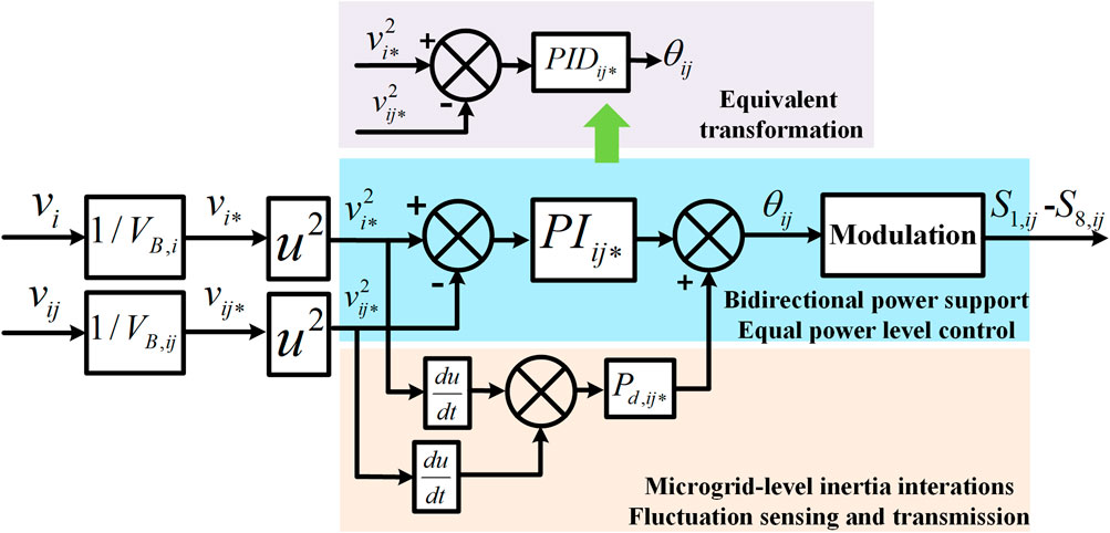
FIGURE 3. Control block diagram of DAB.
The proposed DAB control strategy is a nondirectional control strategy, which can realize bidirectional voltage support without additional fault detection devices. In addition, the control method is decentralized, which only needs the operating measurements on both sides of the DAB and does not rely on communication equipment.
A single DAB structure can be adopted to convert voltage levels between different DC microgrids while forming effective galvanic isolation between the microgrids. When adopting the VSC to connect the AC and DC microgrids, it is often necessary to consider the modulation method’s limitation of the voltage amplitude. To avoid saturation, higher DC voltages are usually required. In sinusoidal pulse width modulation (SPWM), the peak phase voltage should be less than half the DC voltage (Kaura and Blasko, 1995). In space vector pulse width modulation (SVPWM), the peak line-to-line voltage has to be less than the DC voltage (van der Broeck et al., 1988). In practice, to preserve a certain margin, a higher DC voltage is often required when connecting to the AC microgrid. Therefore, DAB can be adopted as part of the unified topology to achieve matching voltages of for the AC and DC microgrids. The low-voltage DC microgrid can also be connected to the higher-voltage AC microgrid by introducing an intermediate stage for voltage matching.
3.3 Control framework and model establishment of voltage source converter
The VSC in IIC is responsible for the conversion and interconnection between the AC and DC. The control principle of the DAB is to focus on the same power level of different microgrids instead of controlling the voltage of a specific side to a preset value, in which the measured value of the DC microgrid voltage represents the balance level of active power supply and demand in microgrids. Extending the control principle of equal power level to the DC/AC microgrid connection, using the frequency of the AC microgrid and the voltage of the DC microgrid as the symbols of active power levels of different microgrids, the control objective of the VSC is to make the DC microgrid voltage and AC microgrid frequency to the same level.
As shown in Figure 4, the DC side’s voltage and the AC side’s frequency are measured, and the equalization of the voltage and frequency becomes the control target. Ignoring changes in the AC voltage amplitude on short timescales, the active power transmitted by the VSC can be measured by the d-axis current, and the transmitted reactive power can be measured by the q-axis current. The difference between the per-unit AC frequency and DC voltage can represent the difference in the active power levels of the DC and AC microgrids, which is adopted as the d-axis current reference after passing through the PI controller. In reality, the AC microgrid and DC microgrids have different requirements for the frequency and DC voltage fluctuation range. Many counties and regions have formulated relevant standards according to their actual situation, such as the IEEE, NE, and UL standards in the United States. Among all kinds of standards, the IEC standard designed by the International Electrotechnical Commission is the widely accepted and adopted international standard. According to IEC 60038, which is widely adopted for standard voltage establishments, the supply voltage should not exceed 10% of the rated operation voltage under normal operations. In addition, IEC 61000 permits the frequency deviation of the public power supply system to be within 1 HZ. In fact, the acceptable range of voltage and frequency selected in practice is also related to the load importance and system capacity. Based on the aforementioned standards, the DC voltage fluctuation is expected to be 10% and AC frequency range is 2% in this study. Thus, parameters
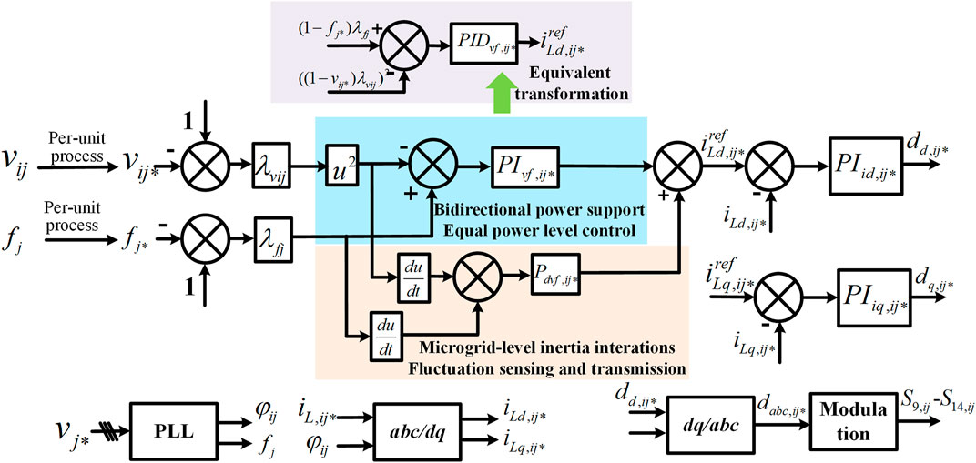
FIGURE 4. Control block diagram of VSC.
According to Li et al. (2019), from the perspective of power balance, the coupling relationship between
Analogously, a linear inertia–implementing control is proposed to regulate the
To make the interfacing converter capable of transmitting the power fluctuation rate, the difference in the differential values of the state quantities should also contribute to the setting of the d-axis current reference value through the proportional controller, which means that the difference of
From the control principle perspective, the proposed DAB and VSC control methods can balance the power levels between microgrids, which enable seamless switching and bidirectional support for the entire hybrid DC/AC microgrids. In addition, the proposed control strategy introduces inertia interactions between the microgrids on both sides on the basis of the active power level balance, which can further strengthen the bidirectional power interaction and supporting ability. Furthermore, power transfer between AC-to-AC microgrids can be realized via a VSC-DAB-VSC structure topology. The proposed equal-active-power-level method can share the active power between AC microgrids. Besides, the reactive power transfer of different AC microgrids can be realized by specifying the reference value of the q-axis current through a higher-level control strategy.
3.4 Power sharing of voltage sources in hybrid microgrids with proposed IIC control strategy
The distributed power sources in the hybrid DC/AC microgrids mainly include renewable energy sources such as photovoltaic and wind power generation, as well as storage devices such as batteries, flywheels, and supercapacitors, which provide voltage and power support for the system. As shown in Figure 1, this study mainly considers power-support renewable energy represented by photovoltaics and wind turbines and voltage-support distributed power represented by storage systems. A maximum power point tracking (MPPT) control strategy is usually adopted for photovoltaic and wind power generation, which can be regarded as a constant power source on a short timescale. The energy storage in each microgrid is mainly adopted to provide voltage support for the system. Therefore, a control algorithm with a fast response and strong robustness is required, which can quickly compensate for the power shortage of the system to improve the equivalent strength of the microgrid when isolated. In addition, it should be possible for the energy storage between different microgrids to be coordinated. When power fluctuations occur in the system, different energy storages should be capable of sharing power fluctuations according to their energy storage capacity, the SOC state, or the set proportional coefficient. There are many works from literature proposing various control strategies for renewable energy sources, which are not the focus of the control method proposed in this study. In this study, the power-support renewable energy adopts the constant-power control method, and the energy storage or other voltage-support distributed power generation adopts the droop control method.
To clearly illustrate the power-sharing ability of voltage sources, the simplified schematic of the system is shown in Figure 5. In this study, a hybrid DC/AC system consisting of three microgrids is selected for modeling, namely, two DC microgrids with different voltage levels and one AC microgrid. Power-support renewable sources such as photovoltaics, voltage-supported sources such as energy storage, constant power loads, or resistive loads are integrated into each microgrid. Different heterogeneous microgrids are interfaced through the proposed unified topology, and the proposed power balance control strategy is adopted. In addition, it is assumed that the utility grid fails to simulate a relatively poor operation scenario. Thus, the breaker of the PCC point is turned off, and the entire hybrid DC/AC system operates in the island state.
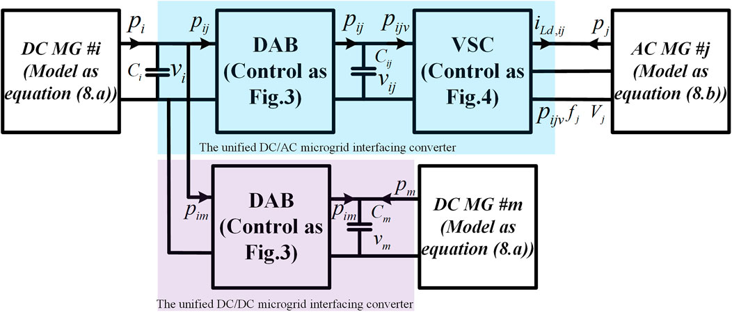
FIGURE 5. Simplified schematic of the three-microgrids system for analysis.
The external characteristic of the combined ESS in each microgrid is characterized by the droop feature, which can be expressed by the following equations. It should be noted that the following models are based on the per unit normalization proposed in Section 2. In addition, since the i-th DC microgrid and the m-th DC microgrid have the same structure, only the i-th DC microgrid model is listed below as a representative:
for ESS in i-th DC microgrid, while
for ESS in j-th AC microgrid.
For different microgrids, the power balance expression can be expressed by Equation 11:
where
As the voltage-support source in hybrid DC/AC microgrids, the energy storage can support the microgrid at a time when a fault is detected. Thus, the stable operation of the entire system is maintained, and the system starts the island operation. Therefore, different energy storages in the system should have the decentralized coordination ability, which means that when a power shortage or excess phenomenon occurs in a microgrid, all energy storages in the entire system can respond and provide coordinated support. Since the proposed unified interlinking converters’ control objective is to balance the active power levels of the microgrids on both sides, considering the operational equivalent characteristics of energy storages in the different microgrids as given in Equation 9, the frequency values of the different AC microgrids and voltage values of the different DC microgrids are equal in the per-unit system. Taking the three-microgrids system shown in Figure 5 as an example, the following equation can be obtained in steady state:
where
This equation can prove that the ratios of different energy storage outputs are inversely proportional to the set droop parameters
4 Stability analysis of typical application scenario with proposed framework
The previous section mainly introduced the unified interfacing topology and control framework of the hybrid DC/AC system with multi-heterogeneous microgrids. This section conducts the stability analysis of typical application scenarios. In the actual design of the system, the design and selection of parameters must first ensure the stability requirements of the system. Therefore, through modeling and stability analysis, the influence of parameter changes on system stability can be observed, by which guidelines for parameter selection can be recommended.
Some basic assumptions are listed before conducting the stability analysis: since there is no reactive power coupling in hybrid microgrids, the reactive power stability only exists in the AC microgrid, which is more straightforward than active power stability. Therefore, this study focuses on the active power stability analysis in hybrid microgrids. Moreover, the voltage amplitude of the AC microgrids can be viewed as constant due to the differences in timescales between the frequency control and voltage control dynamics.
The small-signal model of the interfacing converter can be derived from the following Equation 14:
Linearizing the model near the steady operating point and the small-signal model can be derived as follows:
Analogously, linearizing the characteristics of the power sources as expressed in Equation 9, 10, the corresponding small-signal model is as follows:
By combining Equation 11, the small-signal equations can be derived as
By combining Equations 5 and 15, the small-signal equations of the system composed of the three microgrids can be summarized as
where
Defining the vectors
where
Thus, the small-signal model of the hybrid DC/AC microgrids can be derived as
According to the aforementioned model, the small-signal stability of the hybrid DC/AC microgrids in various operating conditions can be analyzed. The stability analyses of typical operating scenarios are carried out, and the circuit parameters and control parameters adopted are shown in Table 2.
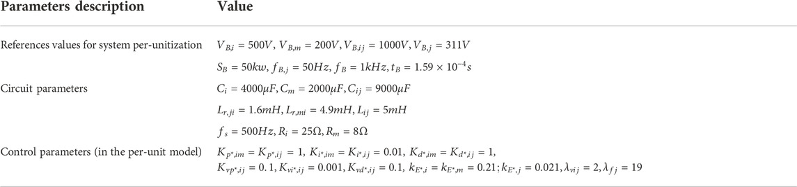
TABLE 2. Circuit parameters and control parameters of typical operating scenarios.
The root locus method is used to analyze the stability of several key control parameters. As the selected parameters change, the root locus diagram is shown in Figure 6 and Figure 7. In order to maintain simplicity, only a few dominant poles close to the virtual axis are reserved for display.
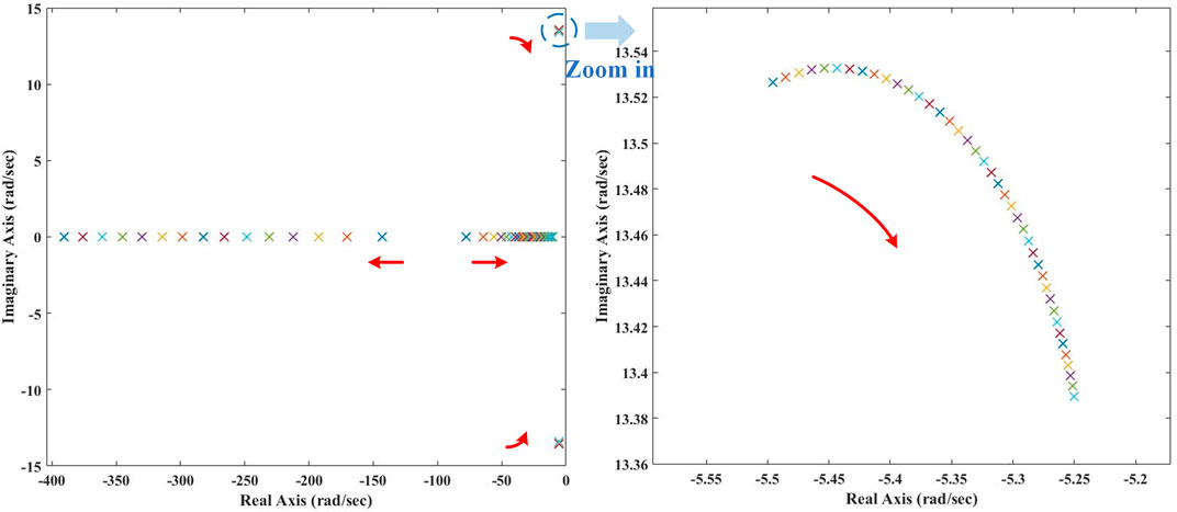
FIGURE 6. Root locus diagram. (A)
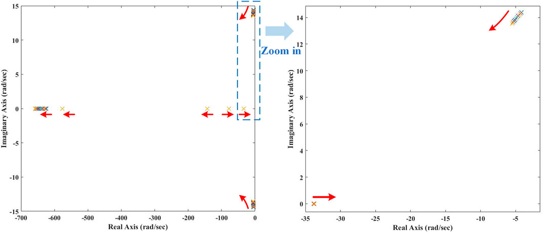
FIGURE 7. Root locus diagram. (A)
According to Figure 6A, the parameters
According to Figure 7, the parameter
This method can also analyze the influence of other parameters on system stability, which will not be repeated in this study.
5 Hardware-in-loop experiments on typical scenarios
To verify the effectiveness of the proposed control strategy, the corresponding HIL experiments are conducted using the RT-LAB and TMS320F28335 digital signal processor (DSP). The equipment of the experiments is as shown in Figure 8, where the circuit is simulated in real-time RT-LAB, and the control algorithm is realized through the DSP. The system configuration and experimental topology are as shown in Figure 1 and Figure 5, respectively, the control methods adopted are as shown in Figure 3 and Figure 4, and the related parameters are set as Table 2.
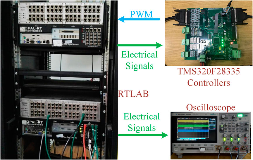
FIGURE 8. Experimental equipment diagram.
5.1 Case I: grid-connected mode
Under regular operation, the hybrid DC/AC system is connected to the utility grid, which has ample power capacity and dispatchable sources and can interact with and support the hybrid microgrids in time. Generally, the utility grid is represented as a three-phase ideal voltage source in simulation and experiment. First, this study tests the control strategy in a grid-connected mode, in which the AC microgrid is connected to the utility grid. The loads are integrated into the medium-voltage DC microgrid (the i-th DC microgrid in Figure 5) and the low-voltage DC microgrid (the m-th DC microgrid in Figure 5). It is assumed that the energy storages in both DC microgrids crash and exit to verify the poor operating conditions. Therefore, the utility grid begins to support the entire hybrid microgrids, and the voltages of the DC microgrids have to be established in time. In this experiment, the low-voltage DC microgrid carries a load of 5 kW, and the carrying load of the medium-voltage DC microgrid switches between 10 kW and 20 kW. It should be noted that in order to display the waveform with an appropriate range on the oscilloscope and make the range of waveform change wide and suitable for observation, a specific linear transformation is carried out on the measured value. For the sake of brevity, the change process of each channel is no longer described, but the range represented by each grid and critical value is shown in the figures.
Figure 9 shows the relative changes of hybrid microgrids adopting the control framework proposed in this study when there is a considerable power fluctuation in a certain microgrid. Since the AC microgrid is connected to the stable utility grid, the measured AC microgrid frequency is kept at 50 Hz. According to the proposed unified control framework for balancing bilateral power levels, the voltages of the DC microgrids should also be around the rated voltage values. According to Figure 9A, the voltages of medium-voltage and low-voltage microgrids are 504 V and 202 V in steady-state operations, respectively, which verifies the effectiveness of the proposed control framework. When there is a sudden drop in the power load of the DC microgrid, such as when the load of the medium-voltage DC microgrid is reduced from 20 kW to 10 kW due to the power imbalance, the microgrid voltage has a sudden rise and then returns to the rated value. Since the AC side is connected to the utility grid, which is equivalent to a stable constant voltage source, the AC frequency basically does not fluctuate, and the utility grid can quickly support the DC side. After the steady state is restored, the DC-side voltages are the same as those before the fluctuation. Meanwhile, it can be observed that under severe power disturbance, the peak values of voltage fluctuations on the DC side are within 10% of the operating voltages, which also meets the operating requirements of the general microgrid. According to Figure 9B, when the power load on the DC side drops sharply, the amplitude of the active current output from the AC side to the DC side drops sharply, and the DC voltage of the intermediate stage also fluctuates to a certain extent. After stabilization, the intermediate voltage can still recover to the rated value.
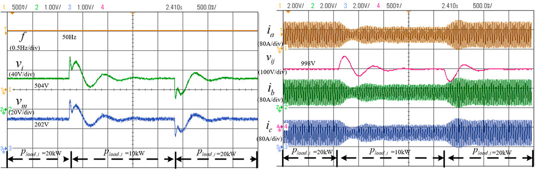
FIGURE 9. System dynamics in case I. (A) Voltages of DC microgrids and frequency of AC microgrid. (B) Three-phase current of VSC and voltage of intermediate stages.
5.2 Case II: island mode
When compared with the grid-connected operation mode, the island operation mode lacks the support of the utility. Thus, power balance has to be realized within the system and the fluctuation ranges of voltages and frequency may become larger. For the operation fluctuation that is similar to case I, the experiment is carried out in the island mode to confirm whether the system can operate stably. In this case, the AC microgrid is equipped with energy storage, and both DC microgrids still have no energy storage. Only the loads are connected to the DC microgrids. Therefore, the AC microgrid has to establish the voltages of the DC microgrids under the proposed bilateral equal-power control framework.
According to Figure 10A, since the AC microgrid is no longer connected to the utility grid, and the energy storage in the AC microgrid adopts the droop control strategy, the AC frequency has an inevitable decrease when compared with the standard value. At the same time, due to the control method of bilateral power equalization, the DC-side voltages also decrease to a certain extent. The frequency and DC voltage variations are calculated to be consistent with Equation 8. When the load on the DC microgrid increases abruptly, power imbalance occurs, the DC voltage drops suddenly, and the sensation of insufficient power is transmitted to the AC side. The AC energy storage output increases, and the frequency of the AC microgrid decreases. The system returns to the previous level when the DC power is reduced. According to Figure 10B, when the DC load increases, the amplitude of the three-phase current increases, and the DC voltage of the intermediate stage decreases to a certain extent, which verifies the response and support ability from the AC to the DC side.
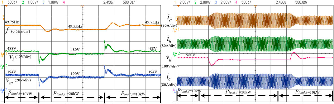
FIGURE 10. System dynamics in case II. (A) Voltages of DC microgrids and frequency of AC microgrid. (B) Three-phase current of VSC and voltage of intermediate stages.
5.3 Case III: verification of energy storage sharing
In addition to maintaining the interaction and power support of the AC and DC microgrids, the proposed control framework is also compatible with energy storage sharing. That is, when power fluctuations occur in any microgrid, all microgrids in the whole system can increase/decrease the output in proportion to respond to the fluctuations in time. In order to verify the function of energy storage sharing on the basis of island operation, energy storage is equipped in each microgrid and its output from each microgrid is observed when power fluctuation occurs. The droop coefficients of energy storages and system control parameters are still the same as in Table 1. The load in the low-voltage DC microgrid is 5 kW, and the load in the medium-voltage DC microgrid ranges from 15 to 30 kW.
According to Figure 11A, in this case where three microgrids are equipped with energy storages when compared with case II where only the AC microgrid is equipped with energy storage, the AC frequency and DC voltages are closer to the standard values. When the power load of the DC microgrid increases suddenly, the frequency and voltages decrease until the load recovers. It can be observed from Figure 11B that when the power demand increases, the output current amplitude of the AC microgrid increases. According to Figure 11C, in the initial state, energy storages in the three microgrids equally share the total 20-kW load in the two DC microgrids. With the sudden increase in load in the medium-voltage microgrid, the energy storage output inside the microgrid increases, as do the energy storage outputs of the other microgrids which gradually increase. Then, the storage output of the medium-voltage microgrid gradually decreases. When the steady state is finally reached, the three storages share the load of 35 kW equally again.
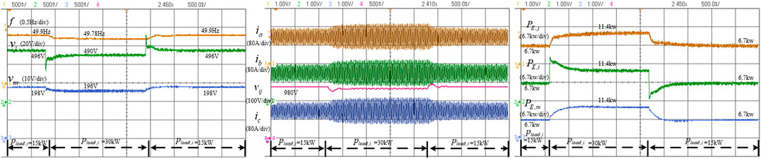
FIGURE 11. System dynamics in case II. (A) Voltages of DC microgrids and frequency of AC microgrid. (B) Three-phase current of VSC and voltage of intermediate stage. (C) Energy storage power output in each microgrid.
In summary, the conducted HIL experiments verify the effectiveness and stability of the proposed control framework, whether the system operates in a grid-connected mode or the island mode. In addition, experiments also prove that the proposed control framework is compatible with energy storage sharing and is suitable for constructing an AC/DC hybrid system with multi-heterogeneous microgrids.
6 Conclusion
This study proposes a unified decentralized control framework for hybrid DC/AC systems composed of multiple heterogeneous microgrids, which include the topology and a corresponding control strategy. Topologically, the DAB is adopted to replace the conventional line frequency transformer to realize the functions of galvanic isolation and DC voltage conversion. In terms of the control method, a bidirectional voltage control strategy is proposed for DAB and VSC. Through the proposed unified control framework, the power level of each microgrid in the hybrid DC/AC system can be balanced, and the voltage sources of each microgrid can cooperate to share the power fluctuation. The stability and effectiveness of the control method are analyzed and verified by HIL experiments.
Data availability statement
The original contributions presented in the study are included in the article/Supplementary Material; further inquiries can be directed to the corresponding author.
Author contributions
All authors listed have made an effective and high-quality contribution to the work and approved it for publication.
Funding
This work is supported in part by the National Natural Science Foundation of China (51877188), in part by the China Postdoctoral Science Foundation (2022M712727), in part by Zhejiang Provincial Key R&D Program under Grant 2022C01161, in part by the Fundamental Research Funds for the Central Universities(226-2022-00053), in part by National Natural Science Foundation of China (U2166203), in part by the National Natural Science Foundation of China (51907175).
Conflict of interest
The authors declare that the research was conducted in the absence of any commercial or financial relationships that could be construed as a potential conflict of interest.
Publisher’s note
All claims expressed in this article are solely those of the authors and do not necessarily represent those of their affiliated organizations, or those of the publisher, editors, and reviewers. Any product that may be evaluated in this article, or claim that may be made by its manufacturer, is not guaranteed or endorsed by the publisher.
References
Ansari, S., Chandel, A., and Tariq, M. (2021). A comprehensive review on power converters control and control strategies of AC/DC microgrid. IEEE Access 9, 17998–18015. doi:10.1109/access.2020.3020035
Begum, M., Li, L., and Zhu, J. (2017). “Distributed control techniques for autonomous AC Microgrid-A brief review,” in 2017 IEEE Region 10 Humanitarian Technology Conference (R10-HTC), 357–362.
Cao, Y., Han, J., He, L., Tan, Y., and Han, J. (2018). Hybrid AC/DC microgrid architecture with comprehensive control strategy for energy management of smart building. Int. J. Electr. Power & Energy Syst. 101 (OCT), 151–161. doi:10.1016/j.ijepes.2018.02.048
Dragičević, T., Lu, X., Vasquez, J. C., and Guerrero, J. M. (2016). DC microgrids—Part I: A review of control strategies and stabilization techniques. IEEE Trans. Power Electron. 31 (7), 4876–4891.
Dragičević, T., Lu, X., Vasquez, J. C., and Guerrero, J. M. (2016). DC microgrids—Part II: A review of power architectures, applications, and standardization issues. IEEE Trans. Power Electron. 31 (5), 3528–3549. doi:10.1109/tpel.2015.2464277
Eghtedarpour, N., and Farjah, E. (2014). Power control and management in a hybrid AC/DC microgrid. IEEE Trans. Smart Grid 5 (3), 1494–1505. doi:10.1109/tsg.2013.2294275
Espina, E., Llanos, J., Burgos-Mellado, C., Cárdenas-Dobson, R., Martínez-Gómez, M., and Sáez, D. (2020). Distributed control strategies for microgrids: An overview. IEEE Access 8, 193412–193448. doi:10.1109/access.2020.3032378
Fang, J., Tang, Y., Li, H., and Li, X. (2018). A battery/ultracapacitor hybrid energy storage system for implementing the power management of virtual synchronous generators. IEEE Trans. Power Electron. 33 (4), 2820–2824. doi:10.1109/tpel.2017.2759256
Guerrero, J. M., Vasquez, J. C., Matas, J., de Vicuna, L. G., and Castilla, M. (2011). Hierarchical control of droop-controlled AC and DC microgrids—a general approach toward standardization. IEEE Trans. Ind. Electron. 58 (1), 158–172. doi:10.1109/tie.2010.2066534
Hossain, M., Pota, H., and Issa, W. (2017). Overview of AC microgrid controls with inverter-interfaced generations. Energies 10 (9), 1300. doi:10.3390/en10091300
Kaura, V., and Blasko, V. (1995). “Operation of a voltage source converter at increased utility voltage,” in Proceedings of Power Electronics Specialist Conference, Atlanta, GA, USA, 523–528.1.
Konar, S., and Ghosh, A. (2015). “Interconnection of islanded DC microgrids,” in 2015 IEEE PES Asia-Pacific Power and Energy Engineering Conference (APPEEC), 1–5.
Krismer, F., and Kolar, J. W. (2009). Accurate small-signal model for the digital control of an automotive bidirectional dual active bridge. IEEE Trans. Power Electron. 24 (12), 2756–2768. doi:10.1109/tpel.2009.2027904
Krismer, F., and Kolar, J. W. (2012). Efficiency-optimized high-current dual active bridge converter for automotive applications. IEEE Trans. Ind. Electron. 59 (7), 2745–2760. doi:10.1109/tie.2011.2112312
Kumar, M., Srivastava, S. C., Singh, S. N., and Ramamoorty, M. (2015). Development of a control strategy for interconnection of islanded direct current microgrids. IET Renew. Power Gener. 9 (3), 284–296. doi:10.1049/iet-rpg.2013.0375
Li, Y., He, L., Liu, F., Li, C., Cao, Y., and Shahidehpour, M. (2019). Flexible voltage control strategy considering distributed energy storages for DC distribution network. IEEE Trans. Smart Grid 10 (1), 163–172. doi:10.1109/tsg.2017.2734166
Malik, S., Sun, Y., Huang, W., Ai, X., and Shuai, Z. (2018). A generalized droop strategy for interlinking converter in a standalone hybrid microgrid. Appl. Energy 226, 1056–1063. doi:10.1016/j.apenergy.2018.06.002
Maryama, V., Zeni, V., Pica, C. Q., Ortmann, M. S., and Heldwein, M. L. (2014). Unified hybrid (AC/DC) active distribution networks droop-based load-sharing strategy. IEEE PES Innov. Smart Grid Technol. Eur., 1–6.
Mi, C., Bai, H., Wang, C., and Gargies, S. (2008). Operation, design and control of dual H-bridge-based isolated bidirectional DC-DC converter. IET Pwr. Electr. 1 (4), 507–517. doi:10.1049/iet-pel:20080004
Nejabatkhah, F., and Li, Y. W. (2015). Overview of power management strategies of hybrid AC/DC microgrid. IEEE Trans. Power Electron. 30 (12), 7072–7089. doi:10.1109/tpel.2014.2384999
Rocabert, J., Luna, A., Blaabjerg, F., and Rodríguez, P. (2012). Control of power converters in AC microgrids. IEEE Trans. Power Electron. 27 (11), 4734–4749, Nov. doi:10.1109/tpel.2012.2199334
Semënov, D., Mirzaeva, G., Townsend, C. D., and Goodwin, G. C. (2017). “Recent development in ac microgrid control — a survey,” in 2017 Australasian Universities Power Engineering Conference (AUPEC), 1–6.
Shamshuddin, M. A., Rojas, F., Cardenas, R., Pereda, J., Diaz, M., and Kennel, R. (2020). Solid state transformers: Concepts, classification, and control. Energies 13 (9), 2319. doi:10.3390/en13092319
van der Broeck, H. W., Skudelny, H. -., and Stanke, G. V. (1988). Analysis and realization of a pulsewidth modulator based on voltage space vectors. IEEE Trans. Ind. Appl. 24 (1), 142–150. doi:10.1109/28.87265
Wang, X., Peng, Y., Chai, J., Xia, Y., Wei, W., and Yu, M. (2020). An ideal DC transformer for active DC distribution networks based on constant-transformation-ratio DABC. IEEE Trans. Power Electron. 35 (2), 2170–2183. doi:10.1109/tpel.2019.2922402
Xia, Y., Yu, M., Peng, Y., and Wei, W. (2018). Modeling and analysis of circulating currents among input-parallel output-parallel nonisolated converters. IEEE Trans. Power Electron. 33 (10), 8412–8426. doi:10.1109/tpel.2017.2777604
Xia, Y., Yu, M., Zhang, Y., Lv, Z., and Wei, W. (2020). Decentralized suppression strategy of circulating currents among IPOP single-phase DC/AC converters. IEEE J. Emerg. Sel. Top. Power Electron. 8 (2), 1571–1583. doi:10.1109/jestpe.2019.2906653
Xu, Q., Xiao, J., Wang, P., and Wen, C. (2017). A decentralized control strategy for economic operation of autonomous AC, DC, and hybrid AC/DC microgrids. IEEE Trans. Energy Convers. 32 (4), 1345–1355. doi:10.1109/tec.2017.2696979
Yan, W., Mo, J., Hu, X., Xiao, F., and Wang, T. (2020). “A practical per-unit method of AC/DC system and dynamic regulation process of UHVDC system under engineering control strategy,” in The 16th IET International Conference on AC and DC Power Transmission (ACDC 2020), 418–423.
Yang, P., Yu, M., Wu, Q., Hatziargyriou, N., Xia, Y., and Wei, W. (2020). Decentralized bidirectional voltage supporting control for multi-mode hybrid AC/DC microgrid. IEEE Trans. Smart Grid 11 (3), 2615–2626. doi:10.1109/tsg.2019.2958868
Yu, H., Niu, S., Shao, Z., and Jian, L. (2022). A scalable and reconfigurable hybrid AC/DC microgrid clustering architecture with decentralized control for coordinated operation. Int. J. Electr. Power & Energy Syst., 107476. doi:10.1016/j.ijepes.2021.107476
Yu, H., Niu, S., Zhang, Y., and Jian, L. (2020). An integrated and reconfigurable hybrid AC/DC microgrid architecture with autonomous power flow control for nearly/net zero energy buildings. Appl. Energy, 114610. doi:10.1016/j.apenergy.2020.114610
Yu, H., Shang, Y., Niu, S., Cheng, C., Ziyun, S., Linni, J., et al. (2022). Towards energy-efficient and cost-effective dc nano grid: A novel pseudo hierarchical architecture incorporating V2G technology for both autonomous coordination and regulated power dispatching. Appl. Energy, 313.
Yu, X., She, X., Ni, X., and Huang, A. Q. (2014). System integration and hierarchical power management strategy for a solid-state transformer interfaced microgrid system. IEEE Trans. Power Electron. 29 (8), 4414–4425. doi:10.1109/tpel.2013.2289374
Zhang, K., Su, M., Sun, Y., Wu, P., Luo, Z., and Han, H. (2021). “A novel distributed control for hybrid AC/DC microgrid with consideration of power limit,” in 2021 IEEE 12th Energy Conversion Congress & Exposition - Asia, 1856–1859.
Keywords: hybrid DC/AC microgrids, decentralized control strategy, unified framework, IIC, bidirectional voltage support
Citation: Li Y, Yang P, Peng Y, Weng C, Sun J, Shen H, Xia Y and Wei W (2023) A unified decentralized framework for isolated interlinking converters of hybrid DC/AC microgrids. Front. Energy Res. 10:1008698. doi: 10.3389/fenrg.2022.1008698
Received: 01 August 2022; Accepted: 30 September 2022;
Published: 11 January 2023.
Edited by:
Liping Guo, Northern Illinois University, United StatesReviewed by:
Linni Jian, Southern University of Science and Technology, ChinaZhenbin Zhang, Shandong University, China
Copyright © 2023 Li, Yang, Peng, Weng, Sun, Shen, Xia and Wei. This is an open-access article distributed under the terms of the Creative Commons Attribution License (CC BY). The use, distribution or reproduction in other forums is permitted, provided the original author(s) and the copyright owner(s) are credited and that the original publication in this journal is cited, in accordance with accepted academic practice. No use, distribution or reproduction is permitted which does not comply with these terms.
*Correspondence: Pengcheng Yang, eXBjMTk2QHpqdS5lZHUuY24=