 Jiahan You
 Dan Xu
95% of researchers rate our articles as excellent or good
Learn more about the work of our research integrity team to safeguard the quality of each article we publish.
Find out more
ORIGINAL RESEARCH article
Front. Energy Res. , 29 September 2022
Sec. Process and Energy Systems Engineering
Volume 10 - 2022 | https://doi.org/10.3389/fenrg.2022.1005796
This article is part of the Research Topic Planning and Operation of Hybrid Renewable Energy Systems, Volume II View all 12 articles
Doubly fed induction generators can participate in frequency support following a disturbance by releasing their rotational energies. However, when regaining the rotor speed, a secondary frequency dip (SFD) tends to produce a sudden output drop. This study suggests a dynamic power-based stepwise inertial control (IC) scheme of a wind power plant for minimizing the SFD while reducing the maximum frequency deviation (MFD), considering the non-negligible wake. To this end, the reference of the output power increases to the torque limit. Afterward, the power reference smoothly decays with the dynamically decreasing incremental power and then automatically switches to the maximum power point tracking operation. The performance of the temporary frequency support with the suggested stepwise IC strategy is investigated with various penetration levels of wind power. Test results demonstrate that the suggested stepwise IC strategy can minimize the SFD and reduce mechanical stresses on the wind turbine during the recovery of the rotor speed while reducing the MFD. Therefore, the suggested stepwise IC strategy secures the dynamic frequency stability of an electric power system dominated by wind power generations.
The electric power system faces challenges of system frequency stability with high-wind-power-penetrated power girds (Wang et al., 2020). The reasons for this phenomenon are explained as follows: doubly fed induction generators (DFIGs) are unable to sustain the system frequency since they decouple the speed of the rotor from the frequency (Xiong et al., 2020; Guo et al., 2022). This results in a reduction in the system inertia response and primary frequency response (Gevorgian et al., 2015; Yang et al., 2021). The range of operation of the DFIG is almost six times that of the conventional synchronous generators (SGs) due to the various characteristics of the DFIG and SG; therefore, the DFIG can be a strong choice to sustain the system frequency (Wang and Tomsovic, 2018). Thus, DFIGs are required to participate in inertial control (IC) to preserve the frequency stability of the power grid.
The IC strategies can be roughly divided into three classifications characterized by the definition of the shape of the power reference: df/dt-based IC, frequency deviation-based IC, and stepwise IC (Morren et al., 2006; Vyver et al., 2016; Li et al.,2017; Hu and WU, 2019; Wu et al., 2019; Kheshti et al., 2019; Peng et al., 2020). The df/dt-based IC can emulate the inertia response to support the reduced inertia response. Frequency deviation-based IC is capable of emulating the primary frequency response to reduce the maximum grid frequency deviation (MGFD). A stepwise IC scheme is determined by the preset power reference trajectories and not the measured grid frequency. The power reference trajectories can be a temporary frequency control trajectory (Yang et al., 2018) and a reliable power reference trajectory (Kheshti et al., 2019). The stepwise IC can boost the grid frequency at a high level owing to the rapid frequency support response (Yang et al., 2018; Kheshti et al., 2019). However, after performing the frequency support response, the rotor speed is required to be regained up to the optimal speed, such a process tends to cause a second frequency drop (SFD) (Lao et al., 2020).
A constant stepwise power reference is addressed to regain the rotor speed (Ullah et al., 2008), and due to the sudden output power drop, an SFD is inevitable. To mitigate the SFD, the authors (Hafiz and Abdennour, 2015) suggest that the power reference of the wind turbines decays in a ramp manner during the recovery period of the rotor speed. The authors (Kang et al., 2016; Xu and Xu, 2017) propose a fixed power reference scheme and a constantly accelerating power reference based on mechanical power to regain the rotor speed, however, the SFD still exists due to the sudden power reduction; furthermore, the output power reduction to counterbalance the SFD and the rotor speed recovery is difficult to determine. A two-level variable coefficient-based controller is designed for DFIG (Xiong et al., 2021). However, the effectiveness of the two-level scheme strongly depends on the predetermined training of the fuzzy controller.
This study addresses a dynamic power-based stepwise IC strategy of the wind power plant with the purpose of minimizing the SFD and mechanical stresses on the wind turbine during the recovery of the rotor speed while reducing the MGFD. To this end, the power reference increases to the torque limit. Afterward, the power reference smoothly decays with the dynamically decreasing incremental power and then automatically switches to the maximum power point tracking operation (MPPTO). The benefits of the proposed stepwise IC strategy are indicated with various penetration levels of wind power.
The mechanical power captured from the wind through the wind turbine can be defined as a nonlinear function of the rotor radius (R), air density (ρ), wind speed (vw), pitch angle (β), tip-speed ratio (λ), and power coefficient (cp), as follows:
In (1), cp has a maximum value (cP, max) at the optimal tip-speed ratio (λopt), where the DFIG can capture the maximum power from the wind. The formula of the MPPTO is as follows:
where PMPPT is the reference for the MPPTO and kg is set to 0.512.
To model the mechanical dynamics, a two-mass shaft model, which is expressed in (6)−(8), is employed in this study (see Figure 1). Twt, Ht, ωt, Tm, Hg, and ωr are the mechanical torques, inertia constants, and rotor speeds of the turbine and generator, respectively. Te is the generator's electrical torque. K and B are the spring constant and damping constant, respectively. θt and θls are the displacements of the angular of the turbine rotor and low-speed shaft, respectively. ωls is the low-speed shaft rotor speed, as shown in (Boukhezzar and Siguerdidjane, 2011).
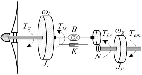
FIGURE 1. Two-mass model.
During the frequency support phase (FSP), active power is injected into the grid by decreasing the rotor speed. When designing the stepwise IC scheme, more attention should be paid to the stalling of the rotor speed. During the rotor speed recovery phase (RSRP), the rotor speed is restored by absorbing the power from the grid; the degree of the SFD should be noticed when designing the control strategy.
As illustrated in Figure 2A, based on the low-order system frequency response model (shi et al., 2018), the system frequency deviation (∆f (t)) in the time domain can be represented as follows:
where ωn, ξ, and ωd are the natural oscillation frequency, damping ratio, and damped frequency, respectively. α and β are the derived coefficients from the SFR model. ∆P is the size of the disturbance.
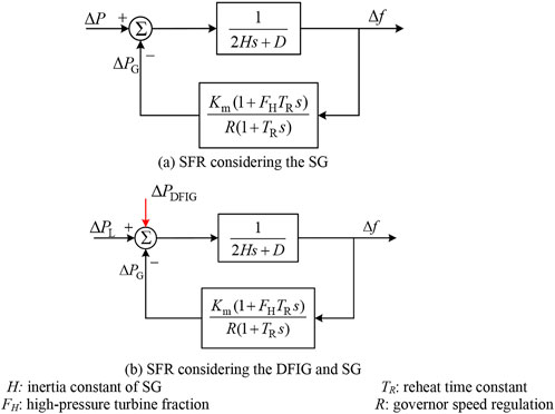
FIGURE 2. SFR of the single machine model.
The maximum frequency deviation and frequency nadir can be given as shown in Eqs 14 and 15, respectively, by deriving the occurrence time of the frequency nadir.
where K1 is the setting value of the primary governor response. fnom, ∆fmax, and fnadir are the nominal system frequency, maximum frequency deviation, and frequency nadir, respectively.
As shown in (Yang et al., 2022), the improved SFR model is represented as shown in Figure 2B. The equivalent size of disturbance (ΔP) is calculated as follows:
where ΔPDFIG indicates the additional power from the DFIG when performing temporary frequency support.
Thus, frequency nadir can be rearranged as follows:
In (Eq. 15), it is evidenced that the DFIG supports system frequency after the system frequency changes. The instantaneous system frequency is higher, thereby reducing the maximum system frequency deviation with the larger ∆PDFIG. Furthermore, in the RSRP, if a larger ∆PDFIG instantly decreases from the power reference, a severe SFD tends to be produced. If ∆PDFIG smoothly decreases, the depth of the SFD can be reduced.
Figure 3 displays the features of the conventional stepwise IC scheme, which includes two sequential stages highlighted in the black line: FSP (line A to C) and RSRP (line C to D). Prior to a severe disturbance, the DFIG operates in the MPPTO, which corresponds to point A. Upon detecting a disturbance, to reduce ∆fmax, the DFIG instantly increases its output power from P0 to PTlim (ω0), which is the torque limit at ω0 and corresponds to point B, as shown in Figure 3. To avoid the stalling of the rotor speed, the power reference for stepwise IC (Pset) is defined as follows:
where PMPPT (ω0) is the power reference of the MPPT operation prior to a disturbance. ωmin is the minimum rotor speed. PMPPT (ωmin) is the value of PMPPT at ωmin.
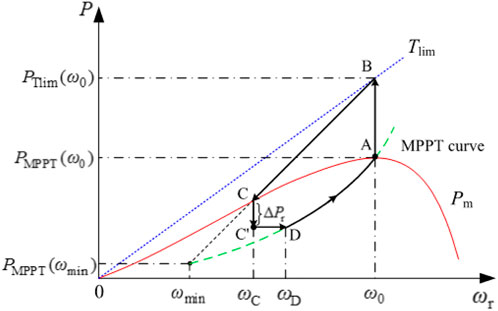
FIGURE 3. Operational concepts of the conventional stepwise IC scheme.
A conventional stepwise IC scheme can reduce the MFD since a certain amount of kinetic energy is rapidly released in the early stage of a frequency disturbance. The released kinetic energy (∆E) during the FSP can be expressed as follows:
where JDFIG represents the moment of inertia of the DFIG. ωC is the rotor speed at operating point C, as shown in Figure 3.
According to the swing equation, since the output power of the DFIG is more than Pm, the rotor speed decreases so that Pset decreases with ωr from operating point B to operating point C. It should be noticed that ωr would converge to point C, which indicates the intersection of the Pm curve and (16). Thus, the conventional stepwise IC strategy avoids stalling of ωr since ωC is located in the stable operating region.
After ωr convergence, the conventional stepwise IC scheme instantly reduces the reference of the output power from Pset (ωC) to Pset (ωC) –∆Pr, so as to restore ωr, and then, is kept until Pset meets the MPPTO curve. At point D, Pref is changed back to PMPPT, as shown in Eq. 5, and then, ωr is restored to ω0. The power reference for lines C to A can be expressed as shown in Eqs 18 and 19. It should be noted that to reduce the depth of the SFD, a small ∆Pr is inevitable; nevertheless, the rotor speed recovery is extended, and vice versa.
To recover the rotor speed at point C, as shown in Figure 3, the swing equations on the DFIG and power system can be expressed as follows:
where HDFIG is the inertial time constant of the DFIG.
As shown in Eqs 20 and 21, ΔPr with rapid variation characteristics causes a subsequent disturbance to the power grid, which leads to an SFD; furthermore, the size of the SFD is dependent on ΔPr. Figure 4 illustrates the results of the conventional stepwise IC strategy with different settings for ΔPr. As shown in (20), with a large ΔPr, the rotor speed recovery is rapid and a severe SFD is produced (as seen in Eq. 21).
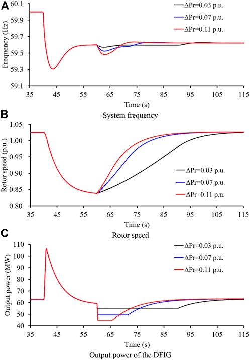
FIGURE 4. Results of the conventional scheme with various forms of ∆Pr.
Implementation of the conventional scheme may face several challenges, which are as follows: 1) The tradeoff between the depth of the SFD and rotor speed recovery is difficult to achieve. 2) The control strategy of the conventional RSR scheme may cause instability issues if a sudden disturbance occurs.
To address the abovementioned issues of the conventional stepwise IC scheme, this study suggests a dynamic power-based stepwise IC of a DFIG, which combines the FSP and RSRP, as shown in Figure 5.
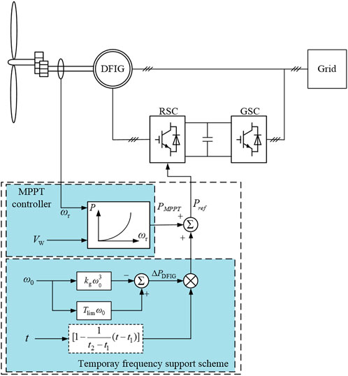
FIGURE 5. Control concept of dynamic power-stepwise IC scheme.
When the system frequency exceeds the deadband, the DFIG starts up the stepwise IC controller. The power reference for stepwise IC is illustrated as follows:
where ΔPDFIG is the incremental power. t1 is the instant of the initiation of the stepwise IC scheme. t2 indicates the instant for meeting the MPPTO curve, and thus, t2−t1 represents the scheduled time for decreasing the ΔPDFIG to 0.
As illustrated in (Eq. 23) and Figure 6, it is evidenced that smaller t2−t1 is able to accelerate the rotor speed restoration, but a severe SFD tends to follow the sudden output drop. Hence, t2−t1 should be not set as too small a value. The large enough t2−t1 can avoid the risk of the SFD but considerably delays the rotor speed restoration. Normally, the rotor speed should be regained before the initiation of the secondary frequency drop. Thus, t2−t1 is set as 10.0–30.0s for different power systems considering the response time of secondary frequency response of the power system.
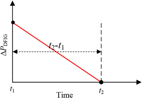
FIGURE 6. Regulation characteristics of ΔPDFIG.
As shown in Figure 7, similar to the conventional stepwise IC scheme, at t0, the power reference increases to PTlim (ω0) corresponding to the operating point A to point B. Afterward, different from the conventional stepwise IC, the incremental power smoothly decreases based on the linear function. Thus, the power reference smoothly decays and automatically switches to the MPPTO curve corresponding to the operating point B to operating point A through operating points C and E.
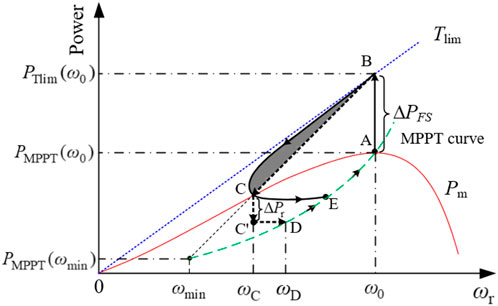
FIGURE 7. Operational concepts of the proposed and conventional stepwise IC schemes.
As illustrated in Figure 7 (ω0→ωC phase), since the solid segment BC is higher than the dotted segment BC, more power is released to the electric grid in the initial stage of a disturbance with the same energy release; as a result, the MFD of the proposed stepwise IC strategy is reduced while ωr is regained earlier than the conventional stepwise IC scheme. The reasons for the solid segment BC being higher than the dotted segment BC are explained as follows.
The derivative functions of Eqs 16 and 20 are represented as follows:
As shown in Eq. 24, dPset/dt decreases with the increasing ωr and is fixed at a constant wind speed condition. Comparing (24) and (25), with ω0 ≤ 1.12 p. u. and dPset/dω0 ≥ dPref/dωr, as a result, the solid segment BC is higher than the dotted segment BC.
In addition, compared with the conventional fixed power-based rotor speed recovery scheme, the output power of the proposed stepwise IC scheme smoothly decreases and automatically switches to the MPPTO curve through the dynamic power reference suggested, as shown in Eq. 22. This process corresponds to the solid segment CE, as shown in Figure 7. Therefore, the smooth decreasing power is a benefit to reducing/removing the second drop on the system frequency and further reducing mechanical stresses on the shaft of the DFIG.
Simulations on various penetration levels of wind power are conducted to explore the performance of the proposed stepwise IC strategy. The model system shown in Figure 8, which comprises a wind farm and six steam turbine SGs, is employed. The droop coefficient for all conventional SGs is set to 5.0%. The deadband of the governor response for all synchronous generators is set to 33 mHz. IEEEX1 is used for voltage control of conventional SGs.
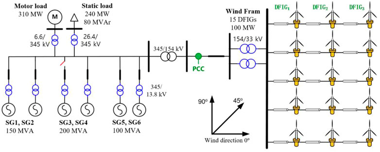
FIGURE 8. Test system.
For calculating the wind speeds of the DFIGs in a wind power plant, the Park wake model, which is based on the Jenson model, is implemented, as illustrated in Figure 9. The wake wind speeds of the DFIGs are derived since the wind direction and cumulative impact of multiple shadowing are considered (Koch et al., 2005). The wind speed of a DFIGi and Vi can be calculated as follows:
where βji indicates the ratio between the swept and overlapping areas of the DFIGi, aj is the factor of the axial induction of the DFIGj, and n is the number of DFIGs in a wind farm.
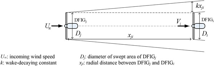
FIGURE 9. Shadow cone.
The wind speeds for the DFIG1, DFIG2, and DFIG3 are 9.0 m/s, 8.4 m/s, and 7.8 m/s, respectively. The available rotor kinetic energies are 3.92, 1.89, and 1.66s, respectively. The parameters of the DFIG are shown in Table 1. To provide clear explanations of the proposed scheme, there are two settings for the proposed and conventional stepwise IC schemes. This first setting is that Δt of the proposed stepwise IC scheme for the first column DFIGs (DFIG1), second column DFIGs (DFIG2), and third column DFIGs (DFIG3) are set as 28.5, 17.0, and 11.0s to achieve the same energy release with the conventional scheme; the second setting is that ΔPr for all DFIGs are set as 0.05 p. u., which is referred in the Technical standards GB, (2018) and 0.10 p. u., respectively.

TABLE 1. Parameters of the DFIG.
As a disturbance, the SG3, which generates 120 MW, is tripped out. Furthermore, the wind penetration level of case 1 and case 2 are 13.6 and 27.3%, respectively. The performance of the proposed stepwise IC strategy is compared to those of the MPPTO and conventional stepwise IC strategy with respect to reducing the MFD, nadir-based frequency response (NBFR), second frequency nadir, and mechanical stresses.
As shown in Figure 10A, the MFD of the MPPTO is 1.222 Hz, which is higher than that of the conventional stepwise IC method by 0.240 Hz, since more kinetic energy is released for the conventional method while no kinetic energy is released for the MPPTO, as shown in Figure 10B. The MFD for the proposed stepwise IC method is 0.964 Hz, which is less than that of the conventional stepwise IC method by 0.018 Hz, even though the same rotor energy is released from DFGs as in the conventional stepwise IC schemes. The reason for this performance is that the injected power is more than that in the conventional stepwise IC method in the initial period of the disturbance (as seen in Figure 10B). The NBFR with the suggested stepwise IC method is 124.48 MW/Hz; however, NBFRs with the conventional stepwise IC method and MPPTO are 122.20 MW/Hz and 98.20 MW/Hz, respectively, as shown in Table 1, due to the higher frequency nadir in the proposed stepwise IC method.
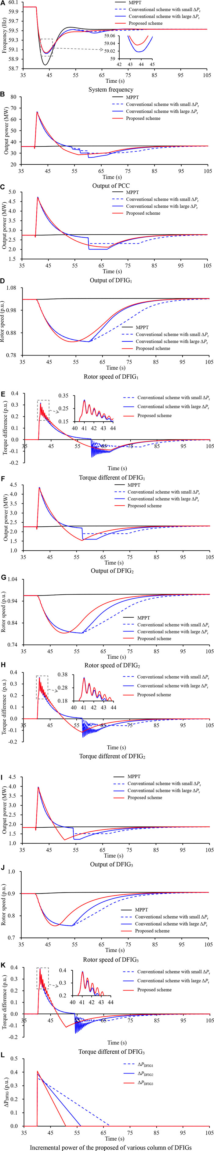
FIGURE 10. Results for case 1.
As shown in Figures 10C, F, and I, the output powers of the conventional stepwise IC scheme suddenly decrease at different instants so that the system frequency drops again. As shown in Figure 10A, the depth of the SFD of the conventional stepwise IC scheme with large ΔPr is less severe than the conventional stepwise IC scheme with small ΔPr. However, the output powers of the DFIG1, DFIG2, and DFIG3 smoothly decay over time until the reference of the output power switches to the MPPTO curve. This is the reason that the suggested stepwise IC scheme can reduce the depth of the SFD. In addition, since the suggested stepwise IC scheme can regulate the time for meeting the MPPTO curve without the requirement of mechanical power, it can ensure the rapid recovery of the rotor speed and system frequency stabilization, as illustrated in Figure 10.
As shown in Figures 10E, H, and K, for the conventional stepwise IC schemes and proposed stepwise IC scheme, mechanical stresses on the wind turbines are caused due to the rapid power increase flow of the disturbance. Such phenomena are inevitable while improving the frequency nadir. However, mechanical stresses of the wind turbines for the conventional stepwise IC schemes are caused due to the rapid power reduction and mechanical stresses become severe with the increasing ΔPr. However, the proposed stepwise IC scheme can avoid mechanical stresses on the wind turbine in the RSRP since the incremental power smoothly decreases to zero, as shown in Figure 10L.
To realize a high wind penetration of 27.3%, SG5 is out of service and the capacity of the wind power plant increases to 150 MW. Thus, the inertial response and primary frequency response of the power system become worse.
As illustrated in Figure 11, the frequency nadir and NBFR with the MPPTO are 58.619 Hz and 86.98 MW/Hz, respectively, which are lower than those of case 1 due to the increased wind power penetration. However, frequency nadirs and NBFRs for the conventional and proposed stepwise IC schemes become better than those in case 1 since the power output of wind power in MW is more than that in case 1. In addition, the improvements of the frequency nadir and NBFR for the suggested stepwise IC scheme are more than that in the conventional stepwise IC schemes.
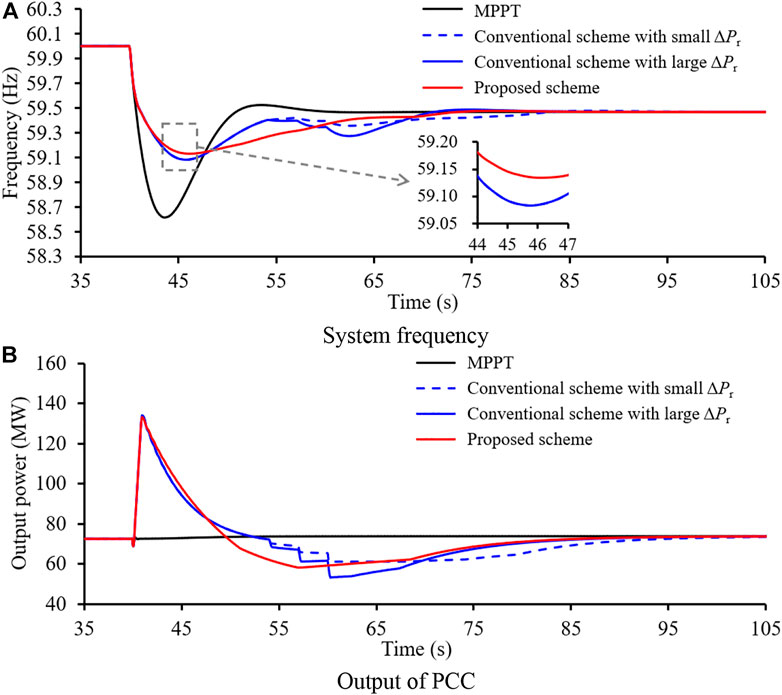
FIGURE 11. Results for case 2.
Output powers of the conventional stepwise IC scheme suddenly decrease at different instants so that the system frequency drops again. As shown in Figure 11A, the depth of the SFD of the conventional stepwise IC scheme with large ΔPr is less severe than the conventional stepwise IC scheme with small ΔPr. In addition, mechanical stresses of the wind turbines are created owing to the rapid power reduction. However, the output powers of the DFIG1, DFIG2, and DFIG3 smoothly decay over time until the reference of the output power switches to the MPPTO curve. This is the reason that the suggested stepwise IC scheme can reduce the depth of the SFD and reduce the mechanical stresses of the DFIGs.
This study proposes a dynamic power-based temporary frequency support scheme for the wind power plant for minimizing the SFD while reducing the MFD. To this end, the reference of the output power increases to the torque limit. Afterward, the power reference smoothly decays with the dynamically decreasing incremental power and then automatically switches to the maximum power point tracking operation. Furthermore, to achieve realistic results, the wake effect is considered in this study.
The results indicate that the proposed stepwise IC strategy can improve the frequency nadir even though the same energy is released from the DFIGs as compared to the conventional stepwise IC schemes in the FSP. The depth of the SFD for the conventional stepwise IC scheme becomes notable and tends to be a lower value for a large wind generation-dominated power system; however, the proposed scheme can minimize the depth of the SFD and reduce mechanical stresses. Moreover, the performances with respect to reducing the MFD, reducing/removing the depth of the SFD, reducing mechanical stresses, and rapidly recovering the rotor speed are more notable in highly wind-penetrated power systems.
The original contributions presented in the study are included in the article/Supplementary Materials; further inquiries can be directed to the corresponding author.
JY, DX, and JC designed the proposed strategy. All authors wrote and edited the manuscript.
The authors declare that the research was conducted in the absence of any commercial or financial relationships that could be construed as a potential conflict of interest.
All claims expressed in this article are solely those of the authors and do not necessarily represent those of their affiliated organizations, or those of the publisher, the editors, and the reviewers. Any product that may be evaluated in this article, or claim that may be made by its manufacturer, is not guaranteed or endorsed by the publisher.
Boukhezzar, B., and Siguerdidjane, H. (2011). Nonlinear control of a variable speed wind turbine using a two mass model. IEEE Trans. Energy Convers. 26 (1), 149–162. doi:10.1109/tec.2010.2090155
Gevorgian, V., Zhang, Y., and Ela, E. (2015). Investigating the impacts of wind generation participation in interconnection frequency response. IEEE Trans. Sustain. Energy 6 (3), 1004–1012. doi:10.1109/tste.2014.2343836
Guo, X., Zhu, D., Zou, X., Yang, Y., Kang, Y., Tang, W., et al. (2022). Analysis and enhancement of active power transfer capability for DFIG-based WTs in very weak grid. IEEE J. Emerg. Sel. Top. Power Electron. 10, 3895–3906. doi:10.1109/JESTPE.2021.3089235
Hafiz, F., and Abdennour, A. (2015).Optimal use of kinetic energy for the inertial support from variable speed wind turbines, Renew. Energy, 80. 629. doi:10.1016/j.renene.2015.02.051
Hu, Y.-L., and Wu, Y.-K. (2019). Approximation to frequency control capability of a DFIG-based wind farm using a simple linear gain droop control. IEEE Trans. Ind. Appl. 55 (3), 2300–2309. doi:10.1109/tia.2018.2886993
Kang, M., Kim, K., Muljadi, E., Park, J. W., and Kang, Y. C. (2016). Frequency control support of a doubly-fed induction generator based on the torque limit. IEEE Trans. Power Syst. 31 (6), 4575–4583. doi:10.1109/tpwrs.2015.2514240
Kheshti, M., Ding, L., Nayeripour, M., Wang, X., and Terzijia, V. (2019). Active power support of wind turbines for grid frequency events using a reliable power reference scheme. Renew. Energy 139, 1241–1254. doi:10.1016/j.renene.2019.03.016
Koch, F., Gresch, M., Shewarega, F., Erlich, I., and Bachmann, U. (2005). “Consideration of wind farm wake effect in power system dynamic simulation,” in Proc. Power Tech, 27-30 June 2005 (Russia: IEEE). doi:10.1109/PTC.2005.4524572
Lao, H., et al. .2020 Innovated inertia control of DFIG with dynamic rotor speed recovery. CSEE J. Power & Energy Syst.2096–0042 .doi:10.17775/CSEEJPES.2020.03180
Li, Y., Xu, Z., and Wong, K. P. (2017). Advanced control strategies of PMSG-based wind turbines for system inertia support. IEEE Trans. Power Syst. 32 (4), 3027–3037. doi:10.1109/tpwrs.2016.2616171
Morren, J., Pierik, J., and de Haan, S. W. H. (2006). Inertial response of variable speed wind turbines. Electr. Power Syst. Res. 76 (11), 980–987. doi:10.1016/j.epsr.2005.12.002
Peng, X., Yao, W., Yan, C., et al. (2020). Two-stage variable proportion coefficient based frequency support of grid connected DFIG-WTs. IEEE Trans. Power Syst., 35, 962–974. doi:10.1109/TPWRS.2019.2943520
shi, Q., Li, F., and Cui, H. (2018). Analytical method to aggregate multi-machine SFR model with applications in power system dynamic studies. IEEE Trans. Power Syst. 33 (6), 6355–6367. doi:10.1109/tpwrs.2018.2824823
Technical standards GB (2018). Wind turbines−Test procedure of gird adaptability. Chinese: GB/T 36994.
Ullah, N. R., Thiringer, T., and Karlsson, D. (2008). Temporary primary frequency control support by variable speed wind turbines—potential and applications. IEEE Trans. Power Syst. 23 (2), 601–612. doi:10.1109/tpwrs.2008.920076
Vyver, J. V. d., Meersman, B., Vandevelde, L., and Vandoorn, T. L. (2016). Droop control as an alternative inertial response strategy for the synthetic inertia on wind turbines. IEEE Trans. Power Syst. 31 (2), 1129–1138. doi:10.1109/tpwrs.2015.2417758
Wang, J., Zhong, H., Yang, Z., Wang, M., Kammen, D. M., Zhu, L., et al. (2020). Exploring the trade-offs between electric heating policy and carbon mitigation in China. Nat. Commun. 11, 6054. doi:10.1038/s41467-020-19854-y
Wang, S., and Tomsovic, K. (2018). A novel active power control framework for wind turbine generators to improve frequency response. IEEE Trans. Power Syst. 33 (6), 6579–6589. doi:10.1109/tpwrs.2018.2829748
Wu, Y.-K., Yang, W. H., Hu, Y. L., et al. (2019). “Frequency regulation at a wind farm using a timing–varying inertia and droop controls,” in ProceedingIEEE Trans. Ind. Appl., 07-10 May 2018.551 (Niagara Falls ON Canada: IEEE), 213–2224. doi:10.1109/ICPS.2018.8369978
Xiong, L., Liu, X., Liu, Y., and Zhuo, F.2020 Modeling and stability issues of voltage-source converter dominated power systems: A review. CSEE J. Power Energy Syst. (Early Access). doi:10.17775/CSEEJPES.2020.03590
Xiong, Y., Yao, W., Fen, J., Lin, S., Ai, X., Fang, J., et al. (2021). Two-level combined control scheme of VSC-mtdc integrated offshore wind farms for onshore system frequency support. IEEE Trans. Power Syst. 36 (1), 781–792. doi:10.1109/tpwrs.2020.2998579
Xu, G., and Xu, L. (2017). Improved use of WT kinetic energy for system frequency support. IET Renew. Power Gener. 11 (8), 1094–1100. doi:10.1049/iet-rpg.2016.0183
Yang, D., Jin, Z., Zheng, T., and Jin, E.2021 An adaptive droop control strategy with smooth rotor speed recovery capability for type III wind turbine generators. Int. J. Electr. Power & Energy Syst. 135, 107532. doi:10.1016/j.ijepes.2021.107532
Yang, D., Kim, J., Kang, Y. C., Muljadi, E., Zhang, N., Hong, J., et al. (2018). Temporary frequency support of a DFIG for high wind power penetration. IEEE Trans. Power Syst. 33 (3), 3428–3437. doi:10.1109/tpwrs.2018.2810841
Keywords: stepwise inertial control, power system control, second frequency dip, mechanical stress, rotor speed recovery
Citation: You J, Xu D and Cao J (2022) Dynamic power-based temporary frequency support scheme for a wind farm. Front. Energy Res. 10:1005796. doi: 10.3389/fenrg.2022.1005796
Received: 28 July 2022; Accepted: 22 August 2022;
Published: 29 September 2022.
Edited by:
Liansong Xiong, Nanjing Institute of Technology (NJIT), ChinaReviewed by:
Tingting Sun, Hefei University of Technology, ChinaCopyright © 2022 You, Xu and Cao. This is an open-access article distributed under the terms of the Creative Commons Attribution License (CC BY). The use, distribution or reproduction in other forums is permitted, provided the original author(s) and the copyright owner(s) are credited and that the original publication in this journal is cited, in accordance with accepted academic practice. No use, distribution or reproduction is permitted which does not comply with these terms.
*Correspondence: Jiangdong Cao, Y2FvamRAanNzYy5lZHUuY24=
Disclaimer: All claims expressed in this article are solely those of the authors and do not necessarily represent those of their affiliated organizations, or those of the publisher, the editors and the reviewers. Any product that may be evaluated in this article or claim that may be made by its manufacturer is not guaranteed or endorsed by the publisher.
Research integrity at Frontiers
Learn more about the work of our research integrity team to safeguard the quality of each article we publish.