 Aleena Swetapadma1
 Shobha Agarwal2Almoataz Y. Abdelaziz3
 Hossam Kotb4
 Kareem M. AboRas4
 Aymen Flah5
 Mokhtar Shouran6*
- 1School of Computer Engineering, KIIT deemed to Be University, Bhubaneswar, India
- 2Department of Higher Technical Education and Skill Development, Ranchi, India
- 3Faculty of Engineering and Technology, Future University in Egypt, Cairo, Egypt
- 4Department of Electrical Power and Machines, Faculty of Engineering, Alexandria University, Alexandria, Egypt
- 5National School of Engineering of Gabes, Gabes University, Gabes, Tunisia
- 6Wolfson Centre for Magnetics, Cardiff University, Cardiff, United Kingdom
Discrimination of different DC faults near a converter end of a DC section consisting of a filter, a smoothing reactor, and a transmission line is not an easy task. The faults occurring in the AC section can be easily distinguished, but the internal and near-side external faults in the DC section are very similar, and the relay may cause false tripping. This work proposes a method to distinguish external and internal faults occurring in the DC section. The inputs are the voltage signals at the start of the transmission line and the end of the converter filter. The difference in voltage signals is calculated and given to an intelligent controller to detect and discriminate the faults. The intelligent controller is designed using machine learning (ML) and deep learning (DL) techniques for fault detection. The long short-term memory (LSTM-) based relay gives better results than other ML methods. The proposed method can distinguish internal from external faults with 100% accuracy. Another advantage is that a primary relay is suggested that detects faults quickly within a fraction of milliseconds. Nevertheless, another advantage is that a backup relay has been designed in case the primary relay cannot operate. Results show that the LSTM-based protection scheme provides higher sensitivity and reliability under different operation modes than the conventional traveling wave-based relay.
Introduction
High voltage direct current (HVDC) transmission lines have been implemented more commonly in the last few decades due to their ability for long-distance power transmission, maximum power transmission, and lossless, among others. However, the transmission lines are always exposed to the environment, with more chances of fault occurrence. Hence, the fast clearance of faults is important to continue the uninterrupted operation of HVDC systems. The problem is that when the fault occurs in the converters (the rectifier side and the inverter side) at one or both terminals of the HVDC transmission system, it will reflect on the transmission line, which is not faulty. In this situation, discriminating between the transmission line faults (internal faults) and the converter end faults (external faults) is very important. In this scenario, the relay of the transmission line may maloperate because, in post-fault conditions, the difference in the magnitude of voltages and currents is small. Moreover, if the fault resistance is high in this condition, then the situation becomes more severe, and the relay will maloperate. Distinguishing between internal and external faults with traveling wave-based methods is difficult, generally used for HVDC transmission line protection. Hence, it is necessary to discriminate the transmission line faults (internal faults) from the converter end faults (external faults) so that the respective relays can operate appropriately.
In recent years, various techniques have been proposed for fault detection in HVDC transmission lines. Saber (2021) used two-end synchronized sampled currents to identify the faulty poles. The change rate of current measurements was used to identify the fault pole to discriminate the ground faults from the metallic return conductor (Haleem and Rajapakse, 2020). A DC line fault detection scheme was proposed using zone partition for multi-terminal DC wind power integration systems (Yang et al., 2021). A protection method based on the transient energy ratio was proposed where the fault identification criterion is put forward based on the impedance-frequency characteristic of the line boundary (Dai et al., 2020). Swetapadma et al. (2021a) suggested a novel method using wavelet transform for fault detection and location in HVDC transmission lines. However, the drawback of this method is that it does not consider converter faults and cannot work with high resistance. Swetapadma et al. (2021b) proposed a long-short term memory network for fault detection and location, but it did not consider the converter faults, which may create problems.
Wu et al. (2017) used the normalized voltage change rate (NVCR), which is the ratio of the maximum voltage change rate to the maximum voltage change in distinguishing external fault from internal fault. Values of NVCR are almost 0.3, similar to the internal faults of high impedance like 50Ω and the external ground faults, which may cause difficulty in discriminating the faults. Li et al. (2020) applied a current limit reactor for the main and backup protection for high resistance faults to discriminate the internal and external faults. With small ground resistance, the peak value of the current has a significant difference in the DC transmission line, and for the external faults, including DC bus faults, the difference is not very satisfactory. It has failed to mention the near distance of the transmission line and the criteria for the selection of an inductor. The rectifier side resistance and inductance between the fault position and the current limiting reactor are not explained. Marvasti and Mirzaei (2018) suggested a method to identify the fault-based DC harmonic current components using FFT. The DC harmonic current components are very high and extracted from the converter transformer tertiary winding to protect the converter from its own fault.
Mehrabi-Kooshki et al. (2020) used a finite difference backward or forward sampled current data. The drawback of this method is that it can give oscillations, and the near-end or far-end faults cannot be identified correctly. Luo et al. (2016) proposed a directional backup protection scheme based on the Hilbert transform to discriminate between internal and external faults. Nevertheless, the drawbacks of this method are that the Hilbert transform with a continuous output of calculation requires instantaneous frequency extraction of the signal. Time delay is also provided to avoid maloperation that will detect a fault in a long time. Extra calculation of energy also increases the time and component size. Xiao et al. (2017) considered an efficient setting calculation method based on two transient electrical parameters for protection. One is a directional element of DC change, and the other is a boundary element for the rate of voltage change. It takes almost 10 ms time for the directional element to act correctly for variation in the rated power. Li et al. (2018) used electromagnet transients for different fault detection where data from both ends are collected with low and high resistance. Kong et al. (2014) studied additional lightning disturbances discriminated from short-circuit faults in a real-time digital simulator with a directional boundary unit for external fault, a starting unit for fault or a disturbance, and a pole identification unit. It has not been shown how the high-frequency component energy is attenuated in external faults but not in the internal faults and the threshold limits under different circumstances in boundary units with the traveling wave. As the wavefront gets refracted and reflected from the fault end, depending on the refractive index of the object which hits, is not the same and the computation technique is used on ideal conditions, which is not practical. In all cases, the time for fault detection is nearly 5.12 ms. Leterme et al. (2016) suggested a protection algorithm using a traveling wave and rate of change of voltage to discriminate between faults. Zhang et al. (2019) used a discrete Fourier transform to get the specific frequency, and a filter was designed. The post-fault harmonic circuit of HVDC is designed for external and internal faults with a current delay time of almost 60 ms. An internal fault is detected 145 ms after the fault occurs to identify the fault type reliably. Li et al. (2009) used current differential protection but for long transmission lines due to the distributed capacitance. The fault detection time is more than 500 ms, which is very slow.
Lee et al. (2022) proposed a frequency and voltage control method for a hybrid HVDC system for integrating an offshore wind farm into transmission networks. Yu and Pang (2022) proposed a pilot protection scheme by using the random matrix for DC lines in the symmetrical bipolar MMC-HVDC grid. Gao et al. (2022) presented a novel controllable line-commutated converter based on the combination of partially and fully controllable semiconductor devices. Liang and Zhang (2022) suggested new time-domain pilot protection based on two-dimensional space projection of dual differential currents for lines connecting converter stations. Li et al. (2022) designed an MMC active power allocation strategy in which, during DC line faults, the constant DC voltage converter is switched to constant active power control, and the other two converters are switched to voltage droop control. A new pilot directional protection scheme for HVDC lines based on grounding resistance was proposed by Ma et al. (2022).
Most of the schemes suggested for HVDC transmission lines use the traveling wave-based method to identify the faults. However, there are various limitations to the traveling wave method. Furthermore, most of these methods have not focused on internal and external faults of the HVDC system. Some of the methods used complex mathematical equation-based algorithms. Hence, to avoid all these shortcomings, artificial intelligence (AI) can be one of the alternatives (Chen et al., 2021; Min et al., 2021; Almalaq et al., 2022; Liu et al., 2022). This work proposes a novel method to discriminate between external and internal DC faults. The internal faults occur from the start of transmission lines to the end of the transmission lines. However, external faults occur at the output of the rectifier end or after a filter or before the start of transmission lines in the DC section. Similarly, the fault of transmission lines finishing ends and filter of inverter ends in the DC side fault can cause false tripping of the relay. These faults are in the DC side, whose impacts are very similar, but the filter side or the inverter end faults are external in nature. AI methods such as machine learning (ML) and deep learning (DL) have been used to discriminate faults. Out of all the AI methods used, the LSTM method performs better than all other methods. The LSTM-based method is not affected by transmission system parameters variation. The LSTM-based method detects the faults within 1 ms time for all the tested fault cases. The proposed method also uses a low sampling frequency compared to other methods. The LSTM-based method identifies the faults with 100% accuracy. The novelty of the proposed work is that it distinguishes external faults from internal faults with better accuracy and helps in primary and backup relay coordination. This study is organized as follows: Section 2 describes the problem, Section 3 discusses the proposed method, Section 4 shows the results, Section 5 presents the discussions of the proposed method, and Section 6 provides the conclusion of the work.
Problems in distinguishing between internal and external faults
The objective of the proposed method is to discriminate between the DC side fault of the converter station and transmission line faults. Figure 1 shows an HVDC transmission line with a rectifier at the relay end and an inverter at the other end, along with different types of DC faults. The faults in HVDC transmission lines are generally single pole-to-ground faults (f1 and f2), as shown in Figure 1. Double pole-to-ground and pole-to-pole faults also occur in HVDC transmission lines. Such types of failures in the transmission line may occur due to, for example, the blowing of heavy winds, falling off a tree, switching surges, or lightning, experiencing different fault resistances due to the fall of the conductor on different objects such as metallic objects, trees, sand, and ground. Faults f1 and f2 are pole-to-ground, which will be detected by the transmission line relay. The proposed method suggests that the relay of the transmission line will be placed at the rectifier end, which will detect the fault in the transmission line for pole 1 and pole 2 using the rectifier end measurements of the transmission line and the converter station measurements. The relay of the transmission line will show output “0” if no fault occurs in the system and “1” during transmission line faults. Hence, the transmission line relay should provide a trip to the circuit breaker during the transmission line faults.
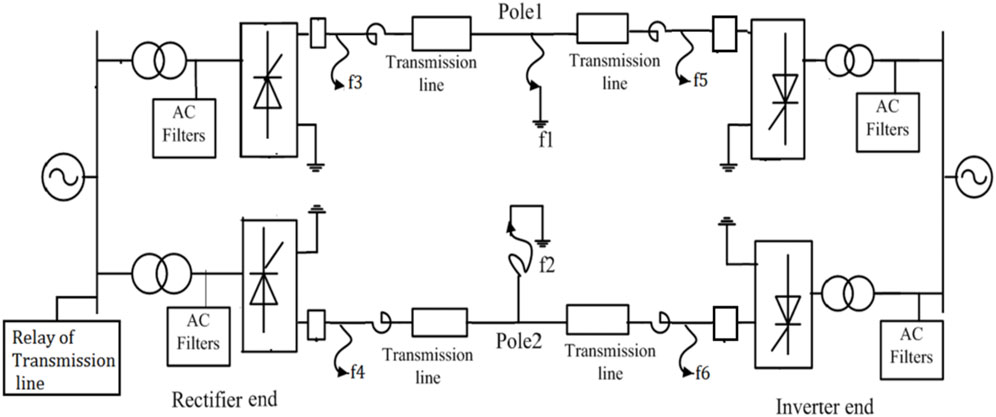
FIGURE 1. Bipolar LCC-HVDC transmission system.
Sometimes there are faults in the converter stations, maybe on the rectifier side (f3 and f4) or the inverter side (f5 and f6), as shown in Figure 1. Faults f3 and f4 are the rectifier end faults, and faults f5 and f6 are the inverter end faults. The faults occurring in DC sections are similar, and the transmission line relay trips even if the fault is external.
Figures 2A,B show the DC voltage signals of pole 1 (
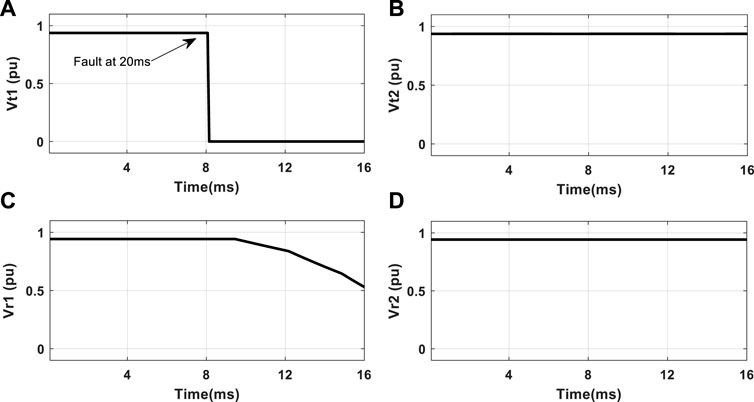
FIGURE 2. Voltage signal of (A) pole 1 of the transmission line, (B) pole 2 of the transmission line, (C) pole 1 of the rectifier station, and (D) pole 2 of the rectifier station during P1G fault at 100 km with R = 0 Ω at 20 ms time.
Figures 3A,B show voltages
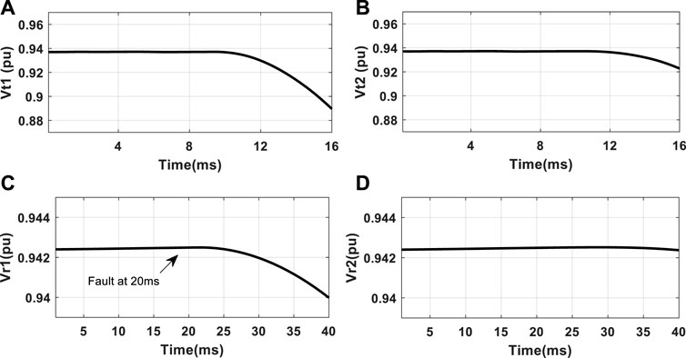
FIGURE 3. Voltage signal of (A) pole 1 of the transmission line, (B) pole 2 of the transmission line, (C) pole 1 of the rectifier station, and (D) pole 2 of the rectifier station during rectifier end DC fault or external fault at 20 ms time.
Hence, a scheme should be designed to discriminate between the different DC converter end and transmission line faults for the appropriate operation of the transmission line relay. The method is designed such that the relay shows output “0” if no fault occurs. The relay shows output “1” if the fault occurs in the transmission line. The relay will show output “2” during the DC side of converter end faults, which means that no faults exist in the transmission line. Hence, during the converter station faults, the transmission line relay should not provide a trip to the circuit breaker. However, the DC side of the converter station should be checked for any type of faults in the converter stations.
The proposed method
The proposed method consists of various sub-steps, such as obtaining the signals, processing the signals, choosing the appropriate fault detection method, and testing the efficiency of the proposed method. Each of the steps will be described in the following sections.
Selection of the inputs
The proposed method has been validated with a 500 kV, 50 Hz bipolar LCC-HVDC transmission line of length 1,100 km, as shown in Figure 1. The proposed system is simulated using MATLAB/SIMULINK (MATLAB, 2018) software. The relay is connected to the rectifier end of the transmission line, providing primary protection to the transmission line. The backup protection will be provided by the relay located at the inverter end. The proposed method uses the voltage signals of the transmission line and the converter station as inputs.
Processing of the inputs
It is necessary to extract features from the signals, which will be able to discriminate the faults. The selected voltage inputs are processed to get appropriate features for fault discrimination. The recorded voltages are studied extensively to find appropriate features for the detection of faults. Voltage extraction and differentiating are implemented during the internal and external faults using two voltage signals obtained from the transmission line (
Figure 4A shows the voltage features of pole 1 during P1G fault at 100 km with R = 0 Ω at 20 ms time. Moreover, Figure 4B shows the voltage features of pole 2 during the P1G fault at 100 km with R = 0 Ω at 20 ms time. Figure 4C shows the voltage features of pole 1 during the rectifier fault at 20 ms time. Figure 4D shows the voltage features of pole 2 during the rectifier fault at 20 ms time.
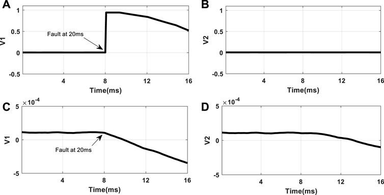
FIGURE 4. (A) Voltage profile of pole 1 during P1G fault at 100 km with R = 0 Ω at 20 ms time. (B) Voltage profile of pole 2 during P1G fault at 100 km with R = 0 Ω at 20 ms time. (C) Voltage profile of pole 1 during the rectifier end DC fault at 20 ms time. (D) Voltage profile of pole 2 during the rectifier fault at 20 ms time.
The optimal features
The voltage features
Internal and external fault discrimination method
This work uses the ML and DL techniques to discriminate between the converter station faults (external faults) and the transmission line faults (internal faults). A flow diagram of the proposed method is shown in Figure 5. As the learning methods have the ability to classify, they can be used effectively in this problem to find the solution. The ML methods have various types, such as ANN, SVM, ANFIS, k-NN, BC, DT, RF, and EL. = The DL methods also have various types, such as LSTM, CNN, and RNN. Among all these methods, the four strongest classification methods are chosen to carry out the proposed work such as ANN (Hagan et al., 2006; Han and Kamber, 2006), RF (Louppe, 2014), EL (Opitz and Maclin, 1999), and LSTM (Goodfellow et al., 2016).
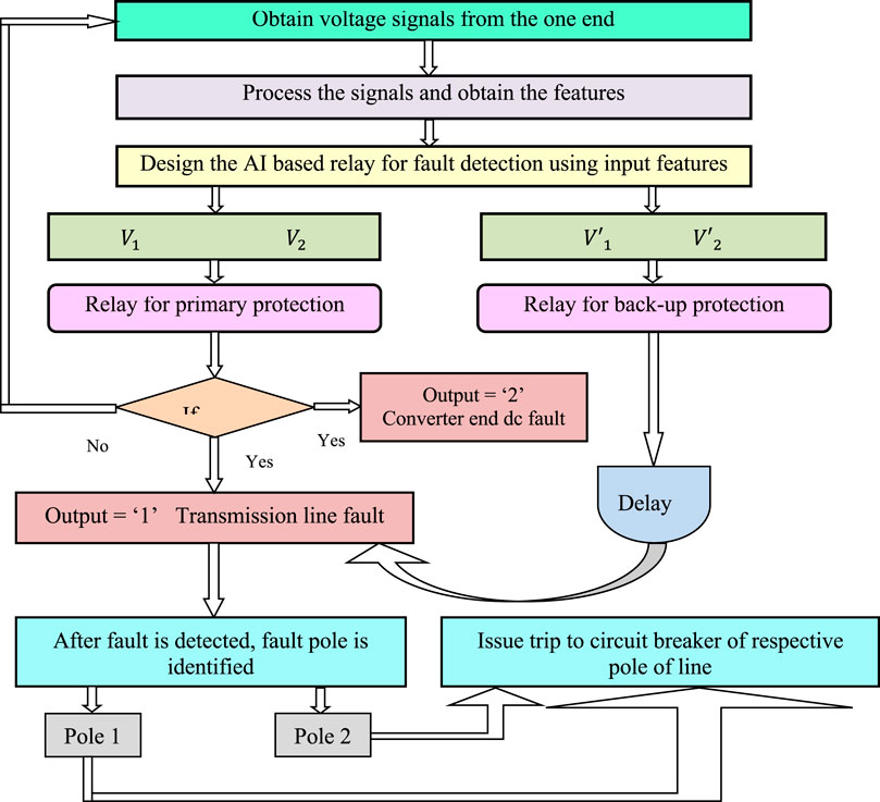
FIGURE 5. Flow diagram of the proposed method.
In ANN, each input (p) given to a neural network is multiplied with a specific weight (w), followed by the summation of these weighted inputs along with the bias (b) in the subsequent layers that follow the input layer, as follows (Hagan et al., 2006):
where f is the activation function. Random forest (RF) is a tree-based learning type used for classification. Generally, with a random selection of the important features, the bagging method is used to classify the data in an RF. The criterion for splitting the data in the RF using the Gini index is given as follows (Louppe, 2014):
Furthermore, ensemble learning (EL) is a combination of different learning machines or classifiers that, in a certain way, gathers all algorithms to generate more accurate and reliable results. Boosting is one of the most prominent model-guided methods to select instances. Mathematically, the classification of instance by AdaBoost can be written as follows (Opitz and Maclin, 1999):
where
LSTM is one of the RNN-based DL methods. In LSTM, three gates, namely, input gate (
where
The output gate is used to provide activation to the final output of the LSTM block at a time stamp t (Goodfellow et al., 2016):
Figure 6 shows the bidirectional LSTM architecture, which is one of the DL algorithms. In this work, the bidirectional LSTM has been used to discriminate between the DC side faults.
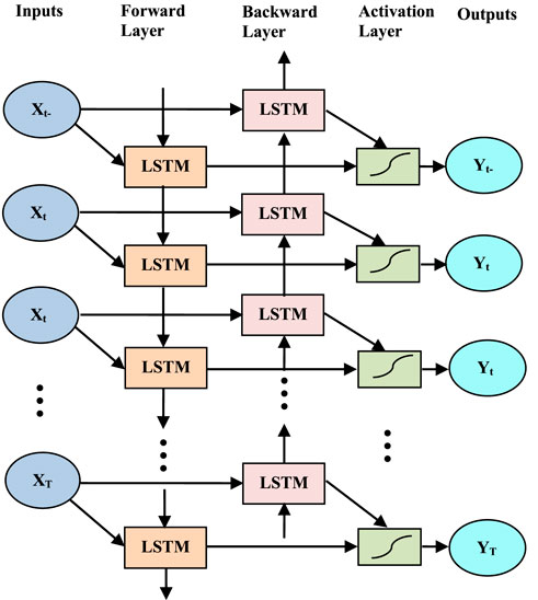
FIGURE 6. Bidirectional LSTM network architecture.
The proposed AI method involves two phases: training and testing. In the training phase, the network has been trained with input features and known targets. For this phase, several training samples are required, which can be obtained by varying different parameters, as illustrated in Table 1. After various trials, the optimal parameters of each method are obtained, which are given in Table 2. Figure 7 shows the training performance of the ANN and LSTM methods. After designing the method, the method performance is evaluated using fault cases as given in Table 1. The performance of the relay has been evaluated and will be discussed in the following section.
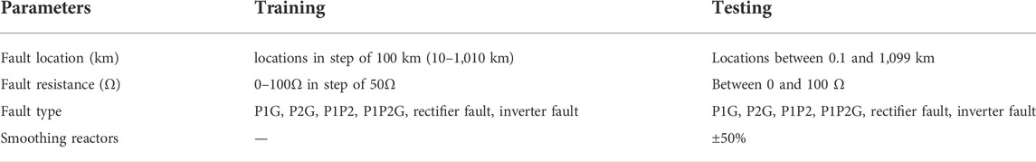
TABLE 1. Change of fault parameters.
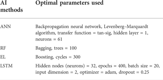
TABLE 2. Optimal parameters used for designing different training modules.
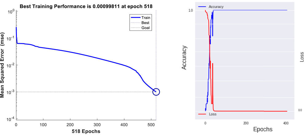
FIGURE 7. Training performance of (A) ANN and (B) LSTM.
Simulation results
The proposed AI method has been evaluated using different fault cases. The different parameters, which are varied, are the fault type, the fault location, the fault resistance, the smoothing reactors, the rectifier station fault, and the inverter station fault. The results of the proposed method are described below.
Performance of the primary relay
Effect of f1 and f2 transmission line faults
In HVDC transmission lines, faults occur involving one pole or both poles. Thus, the proposed method has been tested with various types of faults. Some of the test results are shown in Table 3. Table 3 shows that the fault detection time is within 0.2 ms for all the tested fault cases using the LSTM method. The other three methods have a fault detection time of 0.4 ms. All the faults are also identified correctly as transmission line faults using all methods. Figure 8 shows the inputs and outputs during the P2G fault at 1,000 km with R = 0 Ω at 2 ms. Moreover, Figures 8A,B show the input features of pole 1 and pole 2 during the transmission line fault, respectively. Figures 8C–E show the output that becomes “1” at 2.4 ms after the occurrence of fault at 2 ms showing a transmission line fault for ANN, RF, and EL, respectively. Figure 8F shows the output of the relay using LSTM, which becomes “1” at 2.2 ms after the occurrence of fault at 2 ms showing a transmission line fault.

TABLE 3. Performance results during f1 and f2 faults.
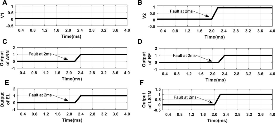
FIGURE 8. (A) Voltage features of pole 1. (B) Voltage features of pole 2. (C) Output of ANN. (D) Output of RF. (E) Output of EL. (F) Output of LSTM during P2G fault at 1,000 km with R = 0 Ω at 2 ms time.
After the transmission line fault is detected, the fault pole is identified for providing a trip to the respective circuit breaker. Various fault cases are used to check the performance of the fault pole identification method. Table 4 shows some of the test results for the fault pole identification during different types of faults for all the used methods. Figure 9 shows the fault pole identification output for all four methods. Results show that all methods identify the fault pole accurately, but the LSTM method takes less time compared to other methods.
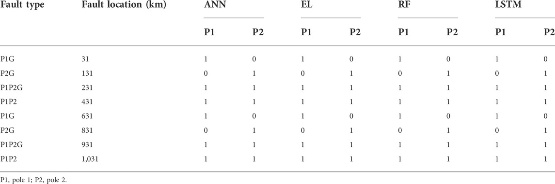
TABLE 4. Performance results during the fault pole identification.
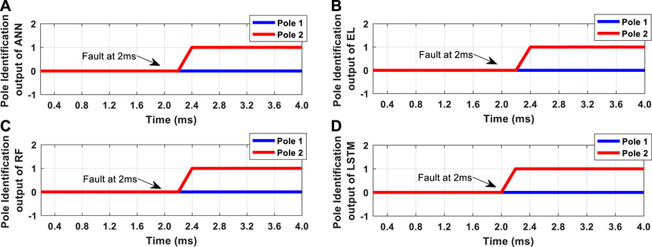
FIGURE 9. Pole identification output of (A) ANN, (B) RF, (C) EL, and (D) LSTM during P2G fault at 1,000 km with R = 0 Ω at 2 ms time.
Effect of fault resistance
Most of the methods designed for transmission lines are affected by fault resistance. In this work, the proposed method has been tested with various fault resistance up to 100 Ω. Table 5 shows the test results of the proposed method for varying fault resistance. Table 5 shows that the fault detection time is within 0.2 ms for all the tested fault cases using the LSTM method. The other three methods have a fault detection time of 0.4 ms. Figure 10 shows the output of all AI-based relays during P1G fault at 1,090 km with R = 100 Ω at 2 ms time. Figures 10A–C show the output of the relay using RF, ANN, and EL, respectively, which becomes “1” at 2.4 ms after the occurrence of fault at 2 ms showing a transmission line fault. Figure 10D shows the output of the relay using LSTM which becomes “1” at 2.2 ms after the occurrence of fault at 2 ms. It has been observed from the results that the proposed method is not affected by fault resistance. Among all the methods, the LSTM-based method can detect faults faster than other methods.
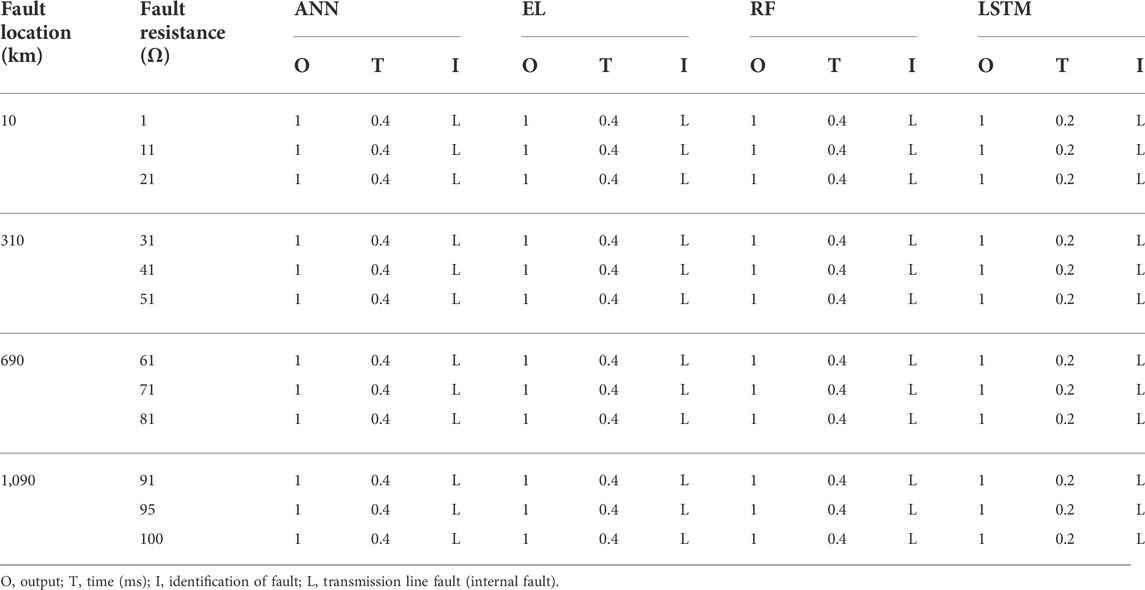
TABLE 5. Performance results with fault resistance.
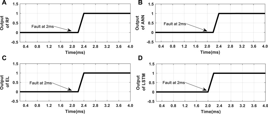
FIGURE 10. Fault detection output, (A) RF, (B) ANN, (C) EL, and (D) LSTM during P1G fault at 1,090 km with R = 100 Ω at 2 ms time.
Effect of boundary faults
Most of the methods are not capable of detecting faults that occur near and far boundaries. The proposed method is tested with various near and far-end faults, and the results are given in Table 6. Table 6 shows that the fault detection time is within 0.2 ms for all the tested boundary fault cases using the LSTM method. The other three methods have a fault detection time of 0.4 ms. It has been observed from the result that the proposed method is not affected by boundary fault. Among all the methods, the LSTM-based method can detect boundary faults faster than other methods.

TABLE 6. Performance results with boundary fault.
Effect of f3 and f4 converter faults
The proposed method has been tested using various DC faults of the converter station, including f3 and f4. Table 7 shows the test results of the proposed method for converter station faults. Table 7 shows that the fault detection time is within 0.2 ms for all the tested fault cases using the LSTM method. The fault detection time is within 4.8 ms for all the tested fault cases using the ANN method. The fault detection time is within 5 ms for all the tested fault cases using the EL method. Moreover, the fault detection time is within 5.4 ms for all the tested fault cases using the RF method. Figure 11 shows the input features and the LSTM output during pole 2 rectifier end station fault. Figures 11A,B show the voltage features of pole 1 and pole 2 during the rectifier station fault at 20 ms time, respectively. Figure 11C shows the output of the relay using LSTM, which becomes “2” after the occurrence of fault at 20 ms showing a converter station DC fault. These types of faults are identified correctly as converter faults.
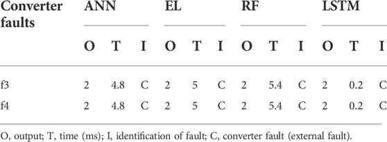
TABLE 7. Performance results during the converter fault.
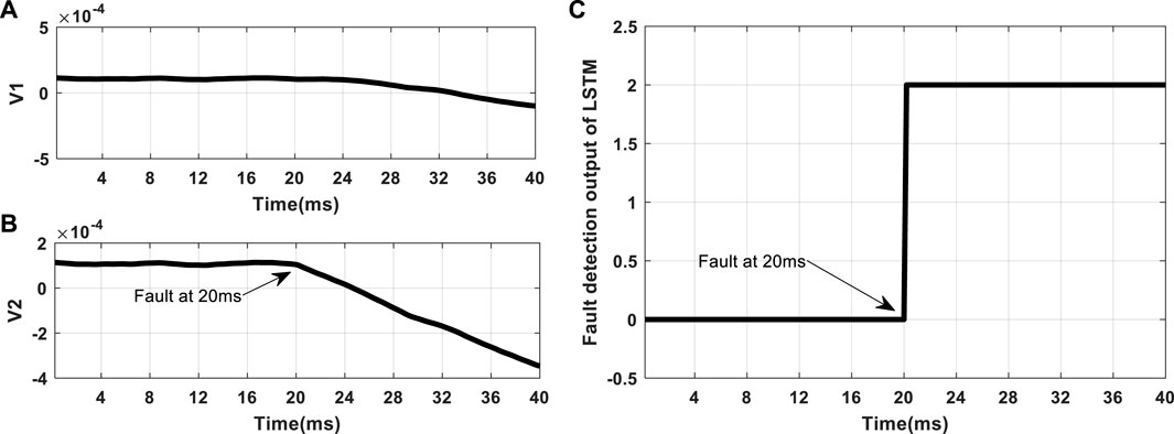
FIGURE 11. (A) Voltage features of pole 1. (B) Voltage features of pole 2. (C) Output of LSTM during rectifier station fault at 20 ms time.
Performance of the backup relay
The proposed method also suggests that there will be one backup relay at the inverter end, which should operate after some delay when the primary relay fails to operate.
Effect of transmission line faults
The proposed method has also been tested for the backup relay during transmission line faults. Table 8 shows the test results of the backup relay for different transmission line faults. The results show that all methods can detect the fault correctly. However, the LSTM method can detect it in a minimum time. Hence, the proposed method has the advantage of detecting transmission line faults correctly even if the primary relay fails.
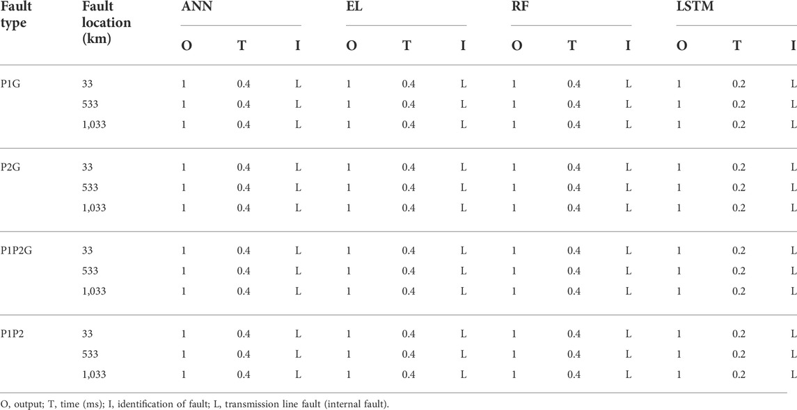
TABLE 8. Performance results of the backup relay during transmission line faults.
Effect of f5 and f6 converter faults
The proposed method has been tested with various DC converter faults, such as f5 and f6. Table 9 shows the test results of the proposed method for these converter station faults. All the faults are identified correctly as converter faults using all methods. Table 9 shows that the fault detection time is within 0.2 ms for all the tested fault cases using the LSTM method, but the detection time is greater for other methods. Hence, it can be concluded that the backup relay detects the converter faults correctly.
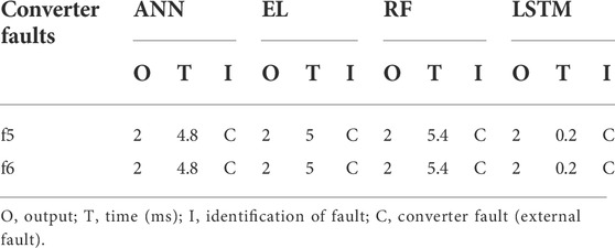
TABLE 9. Performance results of the backup relay during the converter fault.
Discussions
This work suggests a method to discriminate the transmission line faults (internal faults) from the converter station faults (external faults). The features used are the voltage features after processing the DC voltages. In this work, three ML methods (ANN, RF, and EL) and one DL method (LSTM) have been used for fault discrimination. All the methods discriminate between faults correctly, but the detection time is different for all the methods. In this case, around 10,000 fault cases are used to validate the proposed method. The performance of all methods has been compared in terms of the time taken to detect the faults. Figure 12 shows that LSTM has a fault detection time within 0.5 ms for all tested fault cases. However, the other three methods have fault detection times greater than 1 ms for some cases. Hence, LSTM can be considered to be the optimal method for distinguishing between transmission line faults and converter faults.
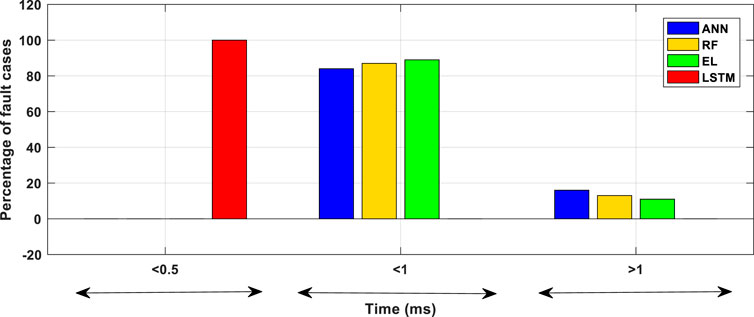
FIGURE 12. Comparison between all methods used for transmission line fault detection.
Previously, various methods have been suggested for the distinction between various faults by researchers. The proposed fault detection method has been compared with other existing methods in terms of sampling rate and the time taken for detection. Table 10 shows the comparison of existing methods with the proposed method. It shows that the proposed method takes less time to detect these types of faults than the other methods. The proposed method also uses a low sampling frequency compared to other methods. By considering the advantages of the proposed method, it can be used efficiently to detect faults in transmission lines.
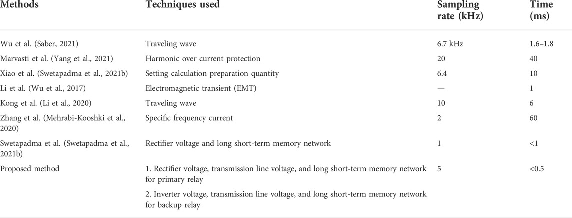
TABLE 10. Comparison with other methods.
Conclusion
This work proposes a novel fault detection method for bipolar LCC-HVDC transmission lines, distinguishing between the transmission line and external faults, which comprise the converter end, smoothing reactor, and filter end fault. The proposed method uses around 10,000 fault cases to validate the method. The sensitivity, specificity, and accuracy of the proposed method are 100%. The proposed method can distinguish between internal and external faults to avoid false tripping of relays. Finally, the proposed method suggests a backup relay in case of failure of the primary relay. It also detects the fault within a fraction of a millisecond of time.
Data availability statement
The original contributions presented in the study are included in the article/Supplementary Material. Further inquiries can be directed to the corresponding authors.
Author contributions
All authors contributed to producing this manuscript.
Conflict of Interest
The authors declare that the research was conducted in the absence of any commercial or financial relationships that could be construed as a potential conflict of interest.
Publisher’s note
All claims expressed in this article are solely those of the authors and do not necessarily represent those of their affiliated organizations or those of the publisher, the editors, and the reviewers. Any product that may be evaluated in this article, or claim that may be made by its manufacturer, is not guaranteed or endorsed by the publisher.
Abbreviations
ANN, artificial neural network; CNN, convolution neural network; DL, deep learning; EL, ensemble learning; HVDC, high voltage direct current; LCC, line commutated converter; LSTM, long short-term memory network; ML, machine learning; RF, random forest; RMS, root mean square; RNN, recurrent neural network;
References
Almalaq, A., Albadran, S., and Mohamed, M. A. (2022). Deep machine learning model-based cyber-attacks detection in smart power systems. Mathematics 10, 2574. doi:10.3390/math10152574
Chen, J., Alnowibet, K., Annuk, A., and Mohamed, M. A. (2021). An effective distributed approach based machine learning for energy negotiation in networked microgrids. Energy Strategy Rev. 38, 100760. doi:10.1016/j.esr.2021.100760
Dai, Z., Liu, N., Zhang, C., Pan, X., and Wang, J. (2020). A pilot protection for HVDC transmission lines based on transient energy ratio of DC filter link. IEEE Trans. Power Deliv. 35, 1695–1706. doi:10.1109/tpwrd.2019.2950350
Gao, C., Yang, J., He, Z., Tang, G., Zhang, J., Li, T., et al. (2022). Novel controllable-line-commutated converter for eliminating commutation failures of LCC-HVDC system. IEEE Trans. Power Deliv. doi:10.1109/TPWRD.2022.3183599
Hagan, M. T., Howard, B., Demuth, M., Beale, H., and De Jes, O. (2006). Neural network design. 2nd edition.
Haleem, N. M., and Rajapakse, A. D. (2020). Fault-type discrimination in HVDC transmission lines using rate of change of local currents. IEEE Trans. Power Deliv. 35 (1), 117–129. doi:10.1109/tpwrd.2019.2922944
Han, J., and Kamber, M. (2006). Data mining: Concepts and techniques. 2nd Ed. Morgan Kaufmann Publishers, Elsevier Inc.
Kong, Fei, Zhiguo, Hao, and Zhang, Song (2014). Development of a novel protection device for bipolar HVDC transmission lines. IEEE Trans. Power Deliv. 29, 2270–2278. doi:10.1109/tpwrd.2014.2305660
Lee, D. K., Moon, S., and Kim, Y. K. (2022). A new communication-free grid frequency and AC voltage control of hybrid LCC-VSC-HVDC systems for offshore wind farm integration. IEEE Trans. Power Syst., 1. doi:10.1109/tpwrs.2022.3171964
Leterme, Willem, Beerten, Jef, and Van Hertem, Dirk (2016). Non-unit protection of HVDC grids with inductive DC cable termination. IEEE Trans. Power Deliv. 31, 820–828. doi:10.1109/tpwrd.2015.2422145
Li, A., Cai, Z., Sun, Q., Li, X., Ren, D., and Yang, Z. (2009). “Study on the dynamic performance characteristics of HVDC control and protections for the HVDC line fault,” in Proc. Power Energy Soc. Gen. Meeting, Calgary, AB, Canada, 1–5.
Li, Chengyu, Gole, Aniruddha M., and Zhao, Chengyong (2018). A fast DC fault detection method using DC reactor voltages in HVDC grids. IEEE Trans. Power Deliv. 33, 2254–2264. doi:10.1109/tpwrd.2018.2825779
Li, Shilong, Chen, Wei, Yin, Xianggen, Chen, Deshu, and Teng, Yufei (2020). A novel integrated protection for VSC-HVDC transmission line based on current limiting reactor power. IEEE Trans. Power Deliv. 35, 226–233. doi:10.1109/tpwrd.2019.2945412
Li, X., Teng, Y., Liu, L., and Fang, G. (2022). A power allocation strategy for DC line fault in serial hybrid LCC-MMC HVDC system. IEEE Access.
Liang, Y. Ren, and Zhang, Z. (2022). Pilot protection based on two-dimensional space projection of dual differential currents for lines connecting MMC-HVDC stations. IEEE Trans. Ind. Electron., 1–12. doi:10.1109/tie.2022.3187572
Liu, L., Wang, B., Ma, F., Zheng, Q., Yao, L., Zhang, C., et al. (2022). A concurrent fault diagnosis method of transformer based on graph convolutional network and Knowledge Graph. Front. Energy Res. 10. doi:10.3389/fenrg.2022.837553
Luo, Shuxin, Dong, Xinzhou, Shi, Shenxing, and Wang, Bin (2016). A directional protection scheme for HVDC transmission lines based on reactive energy. IEEE Trans. Power Deliv. 31, 559–567. doi:10.1109/tpwrd.2015.2461450
Ma, J., Liu, C., Wu, Y., and Phadke, A. G. (2022). A pilot directional protection scheme for LCC-HVDC lines based on grounding resistance. IEEE Trans. Power Deliv., 1. doi:10.1109/tpwrd.2022.3170700
Marvasti, F. D., and Mirzaei, A. (2018). A novel method of combined DC and harmonic over current protection for rectifier converters of monopolar HVDC systems. IEEE Trans. Power Deliv. 33, 892–900.
Mehrabi-Kooshki, Mohammad, Mirhosseini, S. S., and Jamali, S. (2020). Single-end protection algorithm for HVDC transmission lines based on the current difference. IET Generation, Transm. distribution 14, 4339–4351.
Min, L., Alnowibet, K. A., Alrasheedi, A. F., Moazzen, F., Awwad, E. M., and Mohamed, M. A. (2021). A stochastic machine learning based approach for observability enhancement of automated smart grids. Sustain. Cities Soc. 72, 103071. doi:10.1016/j.scs.2021.103071
Opitz, D., and Maclin, R. (1999). Popular ensemble methods: An empirical study. J. Artif. Intell. Res. 11, 169–198. doi:10.1613/jair.614
Saber, A. (2021). A backup protection algorithm for bipolar line-commutated converter HVDC lines. IEEE Syst. J. 15 (1), 1172–1178. doi:10.1109/jsyst.2020.2984612
Swetapadma, A., Agarwal, S., Ranjan, A., and Abdelaziz, A. Y. (2021a). A novel fault distance estimation method for voltage source converter-based HVDC transmission lines. Electr. Power Components Syst. 48, 1–17. doi:10.1080/15325008.2021.1908447
Swetapadma, A., Chakrabarti, S., Abdelaziz, A. Y., and Alhelou, H. H. (2021b). A novel relaying scheme using long short term memory for bipolar high voltage direct current transmission lines. IEEE Access. 9, 119894–119906. doi:10.1109/access.2021.3107478
Wu, J., Li, H., Wang, G., and Yuan, S (2017). An Improved Traveling-Wave Protection Scheme for LCC-HVDC Transmission Lines, IEEE Trans. Power Deliv. 32, 106–116.
Xiao, Hao, Li, Yinhong, Liu, Ruoping, and Duan, Xianzhong (2017). Single-end time-domain transient electrical signals based protection principle and its efficient setting calculation method for LCCHVDC lines. IET Gener. Transm. &. Distrib. 11, 1233–1242. doi:10.1049/iet-gtd.2016.1159
Yang, S., Xiang, W., and Wen, J. (2021). An improved DC line fault detection scheme using zone partition for MTDC wind power integration systems. IEEE Trans. Power Deliv.
Yu, X. W., and Pang, C. (2022). A pilot protection scheme of DC lines for MMC-HVDC grid using random matrix. J. Mod. Power Syst. Clean Energy.
Keywords: HVDC transmission, fault detection, primary protection, backup protection, DC faults
Citation: Swetapadma A, Agarwal S, Abdelaziz AY, Kotb H, AboRas KM, Flah A and Shouran M (2022) A novel primary and backup relaying scheme considering internal and external faults in HVDC transmission lines. Front. Energy Res. 10:1003169. doi: 10.3389/fenrg.2022.1003169
Received: 25 July 2022; Accepted: 01 September 2022;
Published: 21 September 2022.
Edited by:
Mohamed A. Mohamed, Minia University, EgyptReviewed by:
Kittisak Jermsittiparsert, University of City Island, CyprusImane Hammou Ou Ali, Mohammed V University, Morocco
Hassan Farh, Hong Kong Polytechnic University, Hong Kong SAR, China
Copyright © 2022 Swetapadma, Agarwal, Abdelaziz, Kotb, AboRas, Flah and Shouran. This is an open-access article distributed under the terms of the Creative Commons Attribution License (CC BY). The use, distribution or reproduction in other forums is permitted, provided the original author(s) and the copyright owner(s) are credited and that the original publication in this journal is cited, in accordance with accepted academic practice. No use, distribution or reproduction is permitted which does not comply with these terms.
*Correspondence: Mokhtar Shouran, c2hvdXJhbm1hQGNhcmRpZmYuYWMudWs=