 Amjad Ali1
 Zainab Bukhari
 Muhammad Amjad
 Sohail Ahmad
95% of researchers rate our articles as excellent or good
Learn more about the work of our research integrity team to safeguard the quality of each article we publish.
Find out more
ORIGINAL RESEARCH article
Front. Energy Res. , 29 September 2022
Sec. Process and Energy Systems Engineering
Volume 10 - 2022 | https://doi.org/10.3389/fenrg.2022.1002672
This article is part of the Research Topic Modern World Heat Transfer Problems: Role of Nanofluids and Fractional Order Approaches View all 18 articles
This article investigates the pulsatile flow of viscous incompressible MHD nanofluid in a rectangular channel. At the upper and lower walls, the channel has symmetrical constrictions. The goal is to analyze the heat transfer features of the nanofluid flow under the effect of the magnetic field and thermal radiation. Five different nanofluids, formed with nanoparticles of copper
Conventional heat transfer liquid sources are incapable of satisfying current cooling requirements largely due to their poor convective heat transfer coefficients. Researchers have demonstrated that nanoparticles (NPs) usually made of metals or oxides enhance the coefficients of heat convection and conduction in fluids, allowing for higher heat transfer rates for the coolants. Thus, the heat transfer and thermal system effectiveness can be improved significantly by mixing NPs in pure fluid, forming nanofluid (NF). NFs have promising applications in many areas of industry and biomedicine due to their enhanced thermal conductivity. The characteristic of improved thermal conductivity might serve as a major factor for performance improvement. As NFs can enhance heat transfer, heat exchangers can be designed to be both energy efficient and small.
Wang and Mujumdar (2008) investigated the convective heat transfer of NF flow (NFF). Saidur et al. (2011a), Saidur et al. (2011b), Mahian et al. (2013), and Kasaeian et al. (2015) worked to enhance the thermophysical properties as well as heat transfer capacity of the fluids using NPs. The study of these flows through stretching surfaces got motivation from the perspective of its application, particularly in plastic film drawing. Hence, several researchers paid a lot of attention to this issue and studied the movement of boundary layers over different forms of stretching surfaces. Akbar et al. (2014) used a homogeneous model to study NFF at stagnation point above a stretching plate with slip boundary conditions. Analysis of pulsatile flow in a constricted channel under the impact of magnetic field was presented by Bandyopadhyay and Layek (2011) and Bandyopadhyay and Layek (2012). Nasir et al. (2019) explained the Darcy–Forchheimer 2D thin-film fluid of NF. Mustafa et al. (2011) considered the NFF at the stagnation point above a stretching sheet. Wong and Leon (2010) reported that the thermophysical properties of fluids are improved significantly, even at moderate NP concentrations. Haq et al. (2016) investigated the fully developed flow of water-functionalized magnetite NPs among two parallel disks by taking water as the base fluid. The peristaltic flow of incompressible viscous fluid having metallic NPs was examined by Akbar (2014) via an irregular duct. Aly (2020) explained a non-homogeneous two-phase model for
In the magnetohydrodynamic (MHD) flow, the magnetic area induces an electric current in a moving conductive fluid. The induced current causes force on conductive fluid ions. Natural convection under the impact of the magnetic field remained a topic of great interest because of its comprehensive applications in the design of liquid-metal cooling systems, accelerators, and pumps, as well as MHD generators and flow meters (Cha et al., 2002). In a single constricted channel, Ali et al. (2020) investigated the steady and pulsatile modes of non-Newtonian MHD Casson fluid. Sheikholeslami (2017a) researched the hydrothermal study of MHD nanofluid in an open porous cavity by using the Lattice–Boltzmann method with the Brownian motion impact on NF properties. Shah et al. (2019) addressed the idea of the electrical MHD rotational flow of
Kakarantzas et al. (2009) investigated the natural convection of MHD at the sinusoidal upper wall temperature in a vertical cylindrical cavity. Rashidi et al. (2016) examined the convective heat transfer of MHD NFF in a vertical channel with sinusoidal walls. Sheikholeslami (2017b) tested the Buongiorno model to investigate the melting heat transfer of NFF due to the magnetic field. The impacts of heat and mass transfer of NFF flow over a vertical infinite flat plate were investigated by Turkyilmazoglu and Pop (2013). They derived the exact analytical solutions for various water-based NFs containing
Krishna et al. (2021a) and Krishna et al., 2021b) investigated the radiative MHD flow of an incompressible viscous electrically conducting non-Newtonian Casson hybrid NF over vertical moving porous surface under the influence of slip velocity in a rotating frame. Kavya et al. (2022) explore the varying fluid momentum and thermal energy characteristics of the laminar, steady, incompressible, 2D, non-Newtonian pseudo-plastic Williamson hybrid NF over a stretching cylinder with MHD effects.
Shah et al. (2022) determined the heat transfer properties of a MHD Prandtl hybrid NF over a stretched surface in the presence of bioconvection and chemical reaction effects. Zhang et al. (2022) presented the solar source, although it can reduce energy consumption (EC) for buildings on cold days; in the summer, its presence on the envelopes intensifies EC. Gao et al. (2022) examined the hydrodynamic and thermal performances of liquid water in the attendance of two carbon structures by molecular dynamics simulation (MDS). Nayak et al. (2022) conducted a numerical treatment on flow and heat transfer of radiative hybrid NF past an isothermal stretched cylinder set in a porous medium.
The goal of the present work is to numerically investigate the heat transfer characteristics of pulsatile viscous MHD NFF in a constricted channel. The study is conducted for five different nano-impurities (
The following is how the article’s next section is organized. Section 2 defines the mathematical model and transformation. The outcomes and relevant discussions are presented in Section 3. The final remarks are eventually presented in Section 4.
We are working at an incompressible electrically conducting NF flowing via a rectangular channel that should be laminar at Reynolds number 700. The channel walls have a pair of symmetrical constrictions. The resulting electric field
where
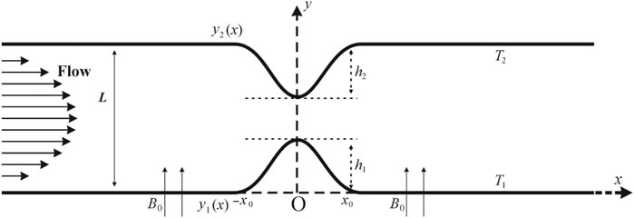
FIGURE 1. The channel geometry with a constriction on each wall. The walls are defined by.
The flow phenomenon is represented by the unsteady incompressible viscous flow equations as follows.
The continuity equation:
The momentum equation:
The energy equation:
where
Then,
Eq. 5 becomes
where
Maxwell’s equation
The dimensionless version of the governing model is created by considering the following quantities:
Here,
The effective dynamic viscosity
where
where
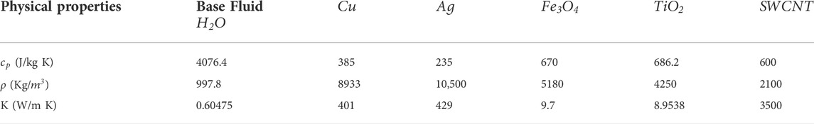
TABLE 1. Thermophysical properties of different NPs and the base fluid.
For the steady case of the flow problem under consideration, the boundary conditions, obtained by solving the dimensionless form of Eq. 8 and performing some manipulations using Eq. 10, are given as follows:
When
The flow is classified as sinusoidal for the pulsatile flow:
Furthermore,
We differentiate Eqs 12, 13 with respect to
And the stream function
For treating the channel walls as the straighten ones, the coordinates are transformed as
Thus, the lower wall symbolizes by
where
The velocity components
Furthermore, the wall boundary conditions in
where
The temperature’s converted boundary conditions are
The other concerning non-dimensional physical quantities comprise the skin-friction coefficient and Nusselt number, defined by
where
By using dimensionless variables from Eq. 9 and the coordinate transformation from Eq. 21, we get
where
The problem Eqs 22–24 is computed using a numerical scheme based on FDM, subject to the relevant boundary conditions in Sections 2.1, 2.3. The numerical scheme adopts a standard approach, as used by Bandyopadhyay and Layek (2011), Bandyopadhyay and Layek (2012), and Ali et al. (2020). The computational domain is assumed as
The pulsatile motion is modeled by adding in the inflow boundary condition the sinusoidal time-dependent function
For validation, the present results for the pulsatile flow condition are compared with those obtained by Bandyopadhyay and Layek (2012) without the heat effect. Figure 2 shows a good agreement of the present results, specifically for the wall shear stress (WSS), with (Bandyopadhyay and Layek, 2012) for
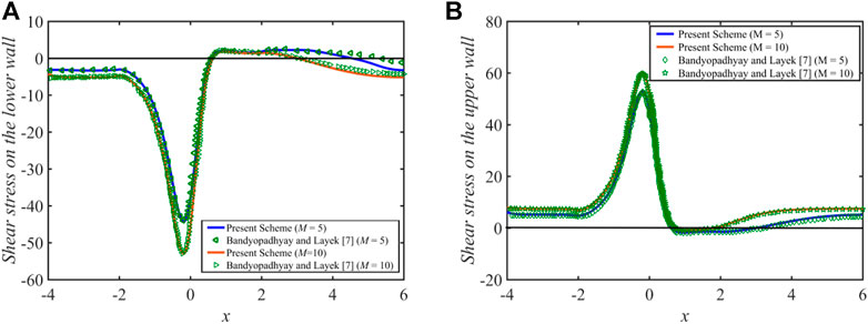
FIGURE 2. WSS distribution for the pulsatile flow, for
The effects of varying the volume fraction on the wall shear stresses (WSS) at the upper wall are computed for
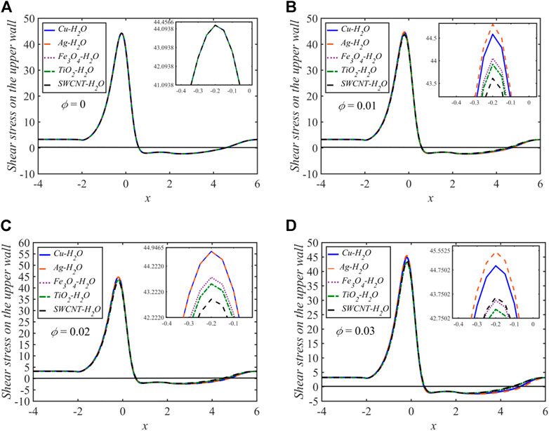
FIGURE 3. The WSS distribution for distinct values of
The velocity and temperature profiles for each of the five NFs for
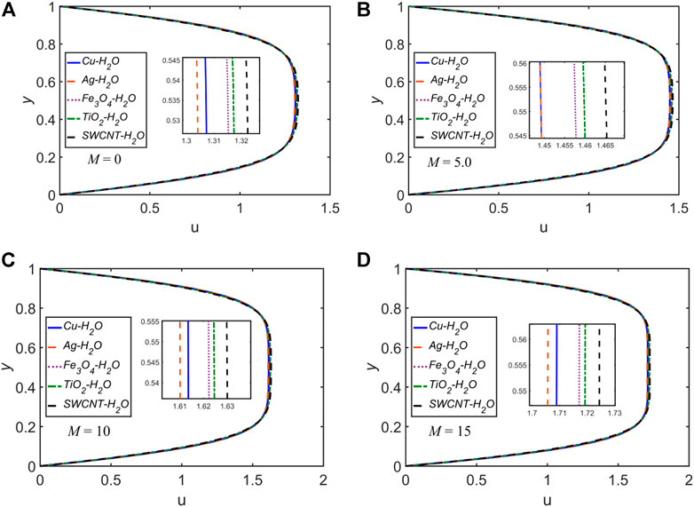
FIGURE 4. The velocity profile
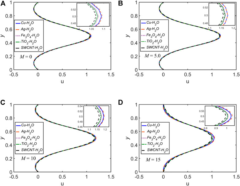
FIGURE 5. The velocity profile
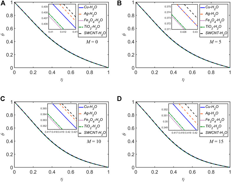
FIGURE 6. The temperature profile
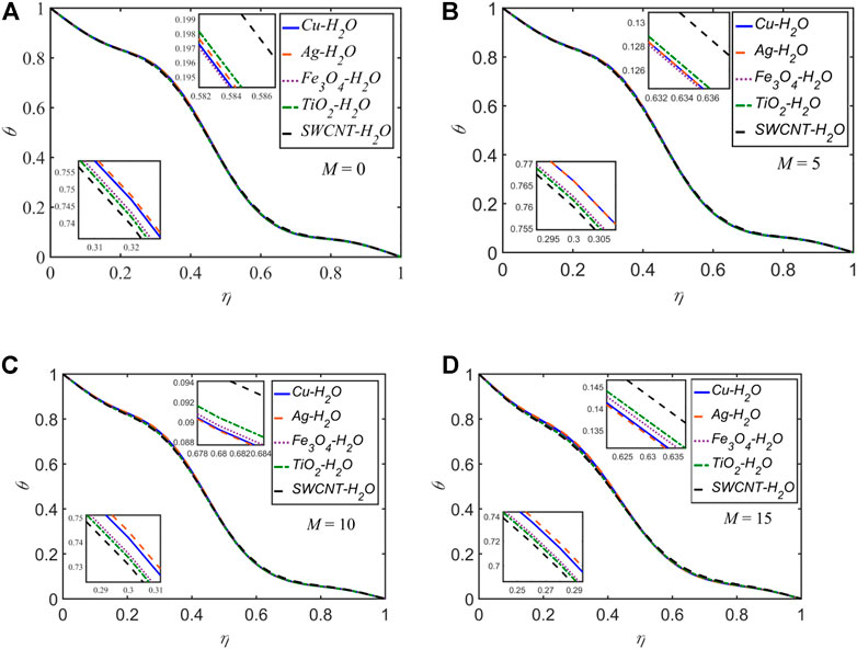
FIGURE 7. The temperature profile
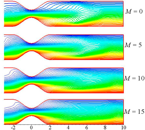
FIGURE 8. The temperature distribution plots for distinct values of
The temperature profiles for each of the five NFs for
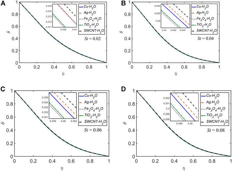
FIGURE 9. The temperature profile
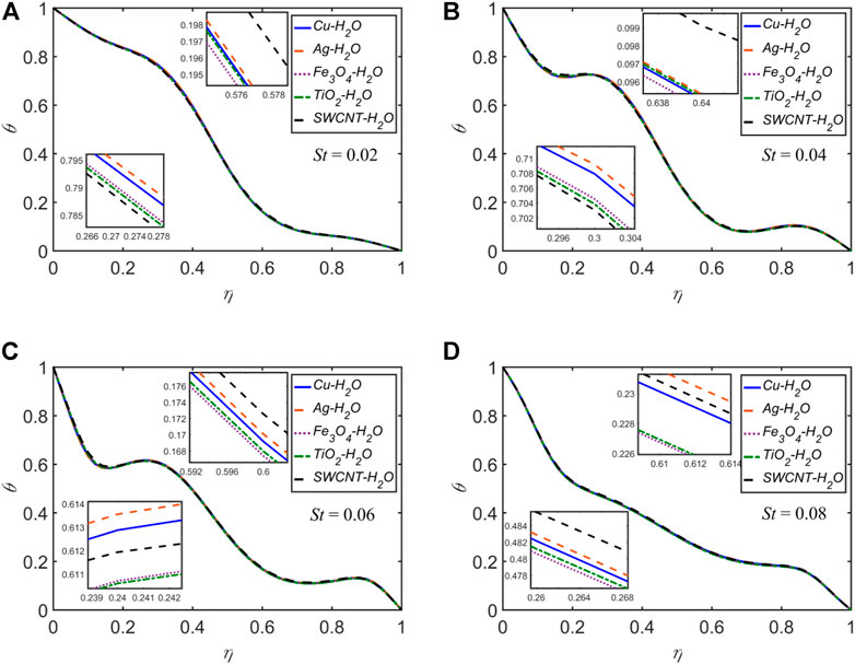
FIGURE 10. The temperature profile
The temperature profiles for each of the five NFs for
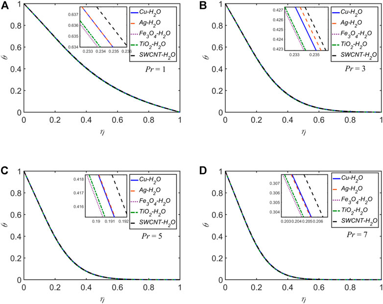
FIGURE 11. The temperature profile
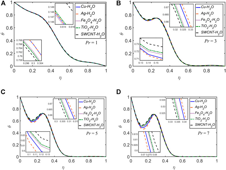
FIGURE 12. The temperature profile
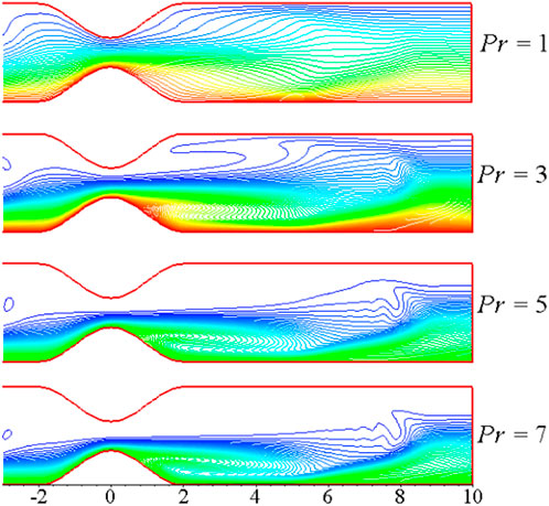
FIGURE 13. The temperature distribution plots for distinct values of
The temperature profiles for each of the five NFs for
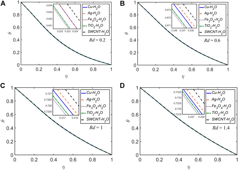
FIGURE 14. The temperature profile
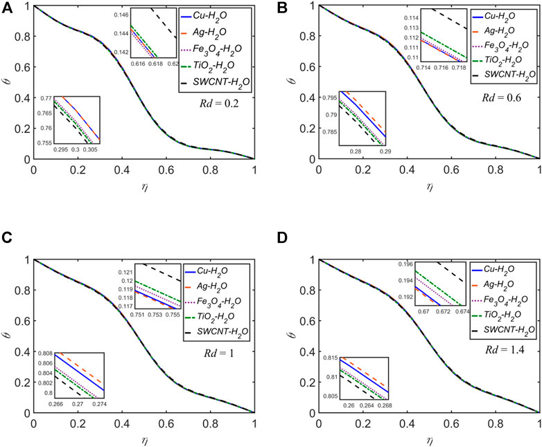
FIGURE 15. The temperature profile
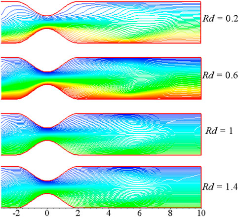
FIGURE 16. The temperature distribution plots for distinct values of
Nearly for all of the cases discussed above, for the variation of any of
The velocity and temperature profiles for each of the five NFs for the four selected time levels:
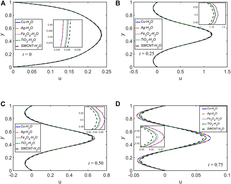
FIGURE 17. The velocity profile
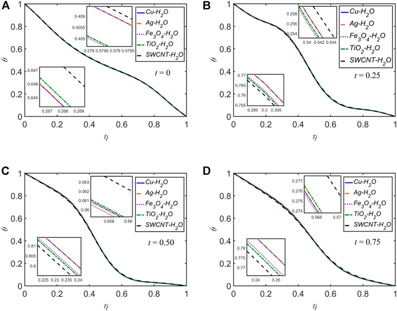
FIGURE 18. The temperature profile
The effects of the variation of the solid volume fraction for
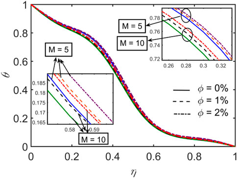
FIGURE 19. The temperature profile
The effects of
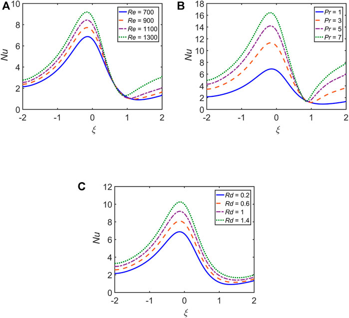
FIGURE 20. Impact of (A)
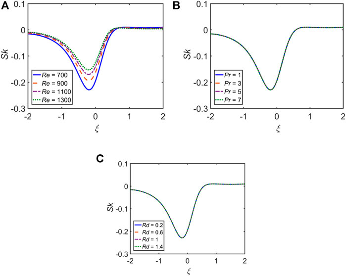
FIGURE 21. Impact of (A)
The streamlines, vorticity, and temperature distribution plots at distinct instants of a pulse cycle with
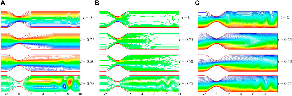
FIGURE 22. (A) Streamlines, (B) vorticity, and (C) temperature distribution plots at the four instants of a pulse cycle with
In this research, the numerical analysis of the pulsatile flow of five different NFs in a channel impacted by the magnetic field and thermal radiation through a rectangular channel having constricted walls is presented. The NPs include
• The streamwise velocity escalates as the values of
• The thickness of the thermal boundary layer rises as any of
• The thickness of the thermal boundary layer declines as any of
• At the throat of the constriction,
• In the lee of the constriction,
• The streamwise velocity attains its maximum at the middle of the constriction at
• During the acceleration and deceleration phases of the pulsation cycle,
• The heat transfer rate is higher for the NF with a higher concentration of the NPs.
• The skin-friction coefficient escalates with escalating values of
The original contributions presented in the study are included in the article/supplementary material; further inquiries can be directed to the corresponding author.
AA: conceptualization; ZB: methodology; MA: validation; S.A.: Coding; ESM Tag El Din: Analysis; SM Hussain: Data Curation.
The authors are grateful to the Deanship of Scientific Research, Islamic University of Madinah, Ministry of Education, KSA, for supporting this research work through research project grant under Research Group Program/1/804.
The authors are thankful to the reviewer for the comments and suggestions. The authors highly appreciate the reviewer for the high standard review.
The authors declare that the research was conducted in the absence of any commercial or financial relationships that could be construed as a potential conflict of interest.
All claims expressed in this article are solely those of the authors and do not necessarily represent those of their affiliated organizations, or those of the publisher, the editors, and the reviewers. Any product that may be evaluated in this article, or claim that may be made by its manufacturer, is not guaranteed or endorsed by the publisher.
Akbar, N. S., Khan, Z. H., and Nadeem, S. (2014). The combined effects of slip and convective boundary conditions on stagnation-point flow of CNT suspended nanofluid over a stretching sheet. J. Mol. Liq. 196, 21–25. doi:10.1016/j.molliq.2014.03.006
Akbar, N. S. (2014). Metallic nanoparticles analysis for the peristaltic flow in an asymmetric channel with MHD. IEEE Trans. Nanotechnol. 13 (2), 357–361. doi:10.1109/tnano.2014.2304362
Ali, A., Farooq, H., Abbas, Z., Bukhari, Z., and Fatima, A. (2020). Impact of Lorentz force on the pulsatile flow of a non-Newtonian Casson fluid in a Constricted channel using Darcy’s law: A numerical study. Sci. Rep. 10, 10629. doi:10.1038/s41598-020-67685-0
Alzahrani, J., Vaidya, H., Prasad, K. V., Rajashekhar, C., Mahendra, D. L., and Tlili, I. (2022). Micro-polar fluid flow over a unique form of vertical stretching sheet: Special emphasis to temperature-dependent properties. Case Stud. Therm. Eng. 34, 102037. doi:10.1016/j.csite.2022.102037
Babu, H., Ajmath, K. A., Venkateswarlu, B., and Narayana, P. V. S. (2018). Thermal radiation and heat source effects on MHD non-Newtonian nanofluid flow over a stretching sheet. J. nanofluids 8, 1085–1092. doi:10.1166/jon.2019.1666
Bandyopadhyay, S., and Layek, G. C. (2011). Numerical computation of pulsatile flow through a locally constricted channel. Commun. Nonlinear Sci. Numer. Simul. 16, 252–265. doi:10.1016/j.cnsns.2010.03.017
Bandyopadhyay, S., and Layek, G. C. (2012). Study of magnetohydrodynamic pulsatile flow in a constricted channel. Commun. Nonlinear Sci. Numer. Simul. 17, 2434–2446. doi:10.1016/j.cnsns.2011.09.040
Cha, J. E., Ahn, Y. C., and Kim, M. H. (2002). Flow measurement with an electromagnetic flowmeter in two-phase bubbly and slug flow regimes. Flow. Meas. Instrum. 12 (5-6), 329–339. doi:10.1016/s0955-5986(02)00007-9
Gao, J., Liu, J., Yue, H., Zhao, Y., Tlili, I., and Karimipour, A. (2022). Effects of various temperature and pressure initial conditions to predict the thermal conductivity and phase alteration duration of water based carbon hybrid nanofluids via MD approach. J. Mol. Liq. 351, 118654. doi:10.1016/j.molliq.2022.118654
Gopal, D., Saleem, S., Jagadha, S., Ahmad, F., Almatroud, A. O., and Kishan, N. (2021). Numerical analysis of higher order chemical reaction on electrically MHD nanofluid under influence of viscous dissipation. Alexandria Eng. J. 60, 1861–1871. doi:10.1016/j.aej.2020.11.034
Haq, R. U., Shahzad, F., and Almdallal, Q. (2017). MHD pulsatile flow of engine oil based carbon nanotubes between two concentric cylinders. Results Phys. 7, 57–68. doi:10.1016/j.rinp.2016.11.057
Kakarantzas, S. C., Sarris, I. E., Grecos, A. P., and Vlachos, N. S. (2009). Magnetohydrodynamic natural convection in a vertical cylindrical cavity with sinusoidal upper wall temperature. Int. J. Heat. Mass Transf. 52, 250–259. doi:10.1016/j.ijheatmasstransfer.2008.06.035
Kasaeian, A., Eshghi, A. T., and Sameti, M. (2015). A review on the applications of nanofluids in solar energy systems. Renew. Sustain. Energy Rev. 43, 584–598. doi:10.1016/j.rser.2014.11.020
Kavya, S., Nagendramma, V., Ahammad, N. A., Ahmad, S., Raju, C. S. K., and Shah, N. A. (2022). Magnetic-hybrid nanoparticles with stretching/shrinking cylinder in a suspension of MoS4 and copper nanoparticles. Int. Commun. Heat Mass Transf. 136, 106150. doi:10.1016/j.icheatmasstransfer.2022.106150
Krishna, M. V., Ahammad, N. A., and Chamkha, A. J. (2021). Radiative MHD flow of Casson hybrid nanofluid over an infinite exponentially accelerated vertical porous surface. Case Stud. Therm. Eng. 27, 101229. doi:10.1016/j.csite.2021.101229
Kumar, M. A., Reddy, Y. D., Rao, V. S., and Goud, B. S. (2021). Thermal radiation impact on MHD heat transfer natural convective nano fluid flow over an impulsively started vertical plate. Case Stud. Therm. Eng. 24, 100826. doi:10.1016/j.csite.2020.100826
Mahian, O., Kianifar, A., Kalogirou, S. A., Pop, I., and Wongwises, S. (2013). A review of the applications of nanofluids in solar energy. Int. J. Heat. Mass Transf. 57, 582–594. doi:10.1016/j.ijheatmasstransfer.2012.10.037
Mahmood, R. T., Asad, M. J., Hadri, S. H., El-Shorbagy, M. A., Mousa, A. A. A., et al. (2022). Hum. Ecol. risk assess.
Mustafa, M., Hayat, T., Pop, I., Asghar, S., and Obaidat, S. (2011). Stagnation-point flow of a nanofluid towards a stretching sheet. Int. J. Heat. Mass Transf. 54, 5588–5594. doi:10.1016/j.ijheatmasstransfer.2011.07.021
Nasir, S., Shah, Z., Islam, S., Bonyah, E., and Gul, T. (2019). Darcy Forchheimer nanofluid thin film flow of SWCNTs and heat transfer analysis over an unsteady stretching sheet. AIP Adv. 9, 015223–15310. doi:10.1063/1.5083972
Nayak, M. K., Mabood, F., Dogonchi, A. S., Ramadan, K. M., Tlili, I., and Khan, W. A. (2022). Wave random complex.
Qi, X., Sidi, M. O., Tlili, I., Ibrahim, T. K., Elkotb, M. A., El-Shorbagy, M. A., et al. (2022). Optimization and sensitivity analysis of extended surfaces during melting and freezing of phase changing materials in cylindrical Lithium-ion battery cooling. J. Energy Storage 51, 104545. doi:10.1016/j.est.2022.104545
Ramadan, K. M., Qisieh, O., and Tlili, I. (2022). Thermal creep effects on fluid flow and heat transfer in a microchannel gas cooling. Proc. Institution Mech. Eng. Part C J. Mech. Eng. Sci. 236, 5033–5047. doi:10.1177/09544062211057039
Rashidi, M. M., Nasiri, M., Khezerloo, M., and Laraqi, N. (2016). Numerical investigation of magnetic field effect on mixed convection heat transfer of nanofluid in a channel with sinusoidal walls. J. Magn. Magn. Mat. 401, 159–168. doi:10.1016/j.jmmm.2015.10.034
Sabu, A. S., Mathew, A., Neethu, T. S., and George, K. A. (2021). Statistical analysis of MHD convective ferro-nanofluid flow through an inclined channel with hall current, heat source and soret effect. Therm. Sci. Eng. Prog. 22, 100816. doi:10.1016/j.tsep.2020.100816
Said, Z., Saidur, R., Sabiha, M. A., Rahim, N. A., and Anisur, M. R. (2015). Thermophysical properties of Single Wall Carbon Nanotubes and its effect on exergy efficiency of a flat plate solar collector. Sol. Energy 115, 757–769. doi:10.1016/j.solener.2015.02.037
Saidur, R., Kazi, S. N., Husain, M. S., Rahman, M. M., and Mohammed, H. A. (2011). Renew. Sust. Energy Rev. 15, 310–323.
Saidur, R., Leong, K. Y., and Mohammed, H. A. (2011). A review on applications and challenges of nanofluids. Renew. Sustain. Energy Rev. 15 (3), 1646–1668. doi:10.1016/j.rser.2010.11.035
Shah, S. A. A., Ahammad, N. A., Din, E. M. T. E., Gamaoun, F., Awan, A. U., and Ali, B., Nanomater. 12, 2174, (2022).
Shah, Z., Bonyah, E., Islam, S., and Gul, T. (2019). Impact of thermal radiation on electrical MHD rotating flow of Carbon nanotubes over a stretching sheet. AIP Adv. 9 (1), 015115–15213. doi:10.1063/1.5048078
Sheikholeslami, M., and Ganji, D. D. (2013). Heat transfer of Cu-water nanofluid flow between parallel plates. Powder Technol. 235, 873–879. doi:10.1016/j.powtec.2012.11.030
Sheikholeslami, M., Ganji, D. D., and Moradi, R. (2017). Forced convection in existence of Lorentz forces in a porous cavity with hot circular obstacle using nanofluid via Lattice Boltzmann method. J. Mol. Liq. 246, 103–111. doi:10.1016/j.molliq.2017.09.053
Sheikholeslami, M., Hayat, T., and Alsaedi, A. (2017). Numerical study for external magnetic source influence on water based nanofluid convective heat transfer. Int. J. Heat. Mass Transf. 106, 745–755. doi:10.1016/j.ijheatmasstransfer.2016.09.077
Sheikholeslami, M. (2017). Influence of magnetic field on nanofluid free convection in an open porous cavity by means of Lattice Boltzmann method. J. Mol. Liq. 234, 364–374. doi:10.1016/j.molliq.2017.03.104
Sheikholeslami, M. (2017). Numerical simulation of magnetic nanofluid natural convection in porous media. Phys. Lett. A 381, 494–503. doi:10.1016/j.physleta.2016.11.042
Sheikholeslami, M., Rashidi, M. M., and Ganji, D. D. (2015). Effect of non-uniform magnetic field on forced convection heat transfer ofFe3O4–water nanofluid. Comput. Methods Appl. Mech. Eng. 294, 299–312. doi:10.1016/j.cma.2015.06.010
Tarakaramu, N., Narayana, P. V. S., and Venkateswarlu, B. (2020). Numerical simulation of variable thermal conductivity on 3D flow of nanofluid over a stretching sheet. Nonlinear Eng. 9, 233–243. doi:10.1515/nleng-2020-0011
Tlili, I., and Alharbi, T. (2022). Investigation into the effect of changing the size of the air quality and stream to the trombe wall for two different arrangements of rectangular blocks of phase change material in this wall. J. Build. Eng. 52, 104328. doi:10.1016/j.jobe.2022.104328
Tlili, I., Sajadi, S. M., Baleanu, D., and Ghaemi, F. (2022). Sustain. Energy Technol. Assess. 52, 102100.
Turkyilmazoglu, M., and Pop, I. (2013). Heat and mass transfer of unsteady natural convection flow of some nanofluids past a vertical infinite flat plate with radiation effect. Int. J. Heat. Mass Transf. 59, 167–171. doi:10.1016/j.ijheatmasstransfer.2012.12.009
Wang, X. Q., and Mujumdar, A. (2008). A review on nanofluids - part II: Experiments and applications. Braz. J. Chem. Eng. 25 (4), 631–648. doi:10.1590/s0104-66322008000400002
Yang, L., Huang, J. N., Ji, W., and Mao, M. (2020). Investigations of a new combined application of nanofluids in heat recovery and air purification. Powder Technol. 360, 956–966. doi:10.1016/j.powtec.2019.10.053
Zhang, J., Sajadi, S. M., Tlili, I., and YangChen, I.Tlili and M. A. Fagiry, (2022). Effects of Al2O3 and TiO2 nanoparticles in order to reduce the energy demand in the conventional buildings by integrating the solar collectors and phase change materials. Sustain. Energy Technol. Assessments 52, 102114. doi:10.1016/j.seta.2022.102114
Keywords: pulsatile flow, constricted channel, heat transfer analysis, nanofluid, carbon nanotube
Citation: Ali A, Bukhari Z, Amjad M, Ahmad S, Tag El. Din ESM and Hussain SM (2022) Newtonian heating effect in pulsating magnetohydrodynamic nanofluid flow through a constricted channel: A numerical study. Front. Energy Res. 10:1002672. doi: 10.3389/fenrg.2022.1002672
Received: 25 July 2022; Accepted: 22 August 2022;
Published: 29 September 2022.
Edited by:
Adnan, Mohi-ud-Din Islamic University, PakistanReviewed by:
Iskander Tlili, National School of Engineers of Monastir, TunisiaCopyright © 2022 Ali, Bukhari, Amjad, Ahmad, Tag El. Din and Hussain. This is an open-access article distributed under the terms of the Creative Commons Attribution License (CC BY). The use, distribution or reproduction in other forums is permitted, provided the original author(s) and the copyright owner(s) are credited and that the original publication in this journal is cited, in accordance with accepted academic practice. No use, distribution or reproduction is permitted which does not comply with these terms.
*Correspondence: Muhammad Amjad, bXVoYW1tYWRhbWphZEBjdWl2ZWhhcmkuZWR1LnBr
Disclaimer: All claims expressed in this article are solely those of the authors and do not necessarily represent those of their affiliated organizations, or those of the publisher, the editors and the reviewers. Any product that may be evaluated in this article or claim that may be made by its manufacturer is not guaranteed or endorsed by the publisher.
Research integrity at Frontiers
Learn more about the work of our research integrity team to safeguard the quality of each article we publish.