 Lei Zhou1
 Shaocheng Wu
- 1Skill Training Center of State Grid Jiangsu Electric Power Co LTD, Suzhou, Jiangsu, China
- 2Jiangsu Province Electric Power Co, LTD, Danyang Power Supply Branch, Danyang, Jiangsu, China
- 3State Grid Jiangsu Technology and Training Center, Suzhou, Jiangsu, China
- 4School of Electrical Engineering and Automation, Wuhan University, Wuhan, Hubei, China
The bypass operation method of mobile transformer vehicles is a common method for the maintenance or replacement of transformers in distribution lines. Using the bypass operation method could avoid power outages and ensure the reliability of electricity consumption. However, the transient characteristics of mobile transformer vehicles connected to the grid can have an impact on their power quality. In response to this problem, this study built a model based on MATLAB/Simulink to model the process of grid connection. The simulation analyzed the current and voltage waveforms of the transient process of grid connection. Moreover, a combination of time-domain and frequency-domain analysis was used to analyze the transient overvoltage and overcurrent conditions of the grid connection. Finally, the effects of two overcurrent suppression methods, adjustment of the closing angle method and the series closing resistance method, were analyzed. These studies provide theoretical guidance for engineering applications, which could strengthen the stability of the distribution network.
Introduction
Live working is an effective method that ensures the reliability of the power supply (Fang et al., 2020a; Gao et al., 2020). In distribution lines, live working can ensure that during maintenance, the user side remains uninterrupted. Live working on distribution lines is mainly divided into the hot-stick method, insulated glove method, and comprehensive uninterrupted operation method. The comprehensive uninterrupted operation method is mainly divided into the cable vehicle bypass operation method, mobile generator vehicle operation, and mobile transformer vehicle bypass operation method. Among these, the mobile transformer vehicle bypass operation method is commonly used to maintain or replace transformers in distribution lines. In the operation process, the addition of a mobile transformer vehicle can shorten the power outage time or even avoid it, which ensures the reliability of power consumption (Luo et al., 2009; Deng and Pei, 2018; Feng et al., 2019; Fu et al., 2020). In addition, the mobile transformer vehicle can also provide temporary capacity increase power for seasonal power loads (Hu et al., 2016).
Over the past few decades, the mobile transformer vehicle has attracted the attention of researchers and engineers (Sawada et al., 1991; Cote and Pelletier, 1995; Wen et al., 2019; Sun, 2021). Sawada et al. (1991); Cote and Pelletier (1995) studied the automatic technology of interrupted operation, which promotes the intelligent development of mobile transformer vehicles. Wen et al. (2019); Sun (2021) put forward a new idea for the structure of mobile transformer vehicles and designed a new type of mobile transformer vehicle with more reliability. Sun et al. (2021) designed mobile transformer vehicles with 20 kV and 10 kV dual-voltage interfaces, which broaden the application range. The aforementioned research mainly focused on intelligent technology and the structure design of mobile transformer vehicles. Hu et al. (2016); Wang et al. (2016) applied mobile transformer vehicles in engineering practice and completed bypass operations. However, there is currently a lack of research on the transient characteristics of the bypass operation of the mobile transformer vehicle, which makes it impossible to determine the impact on the user side during the operation.
In this study, a simulation model of a 10-kV distribution network and mobile transformer vehicle was established. Based on the model, the characteristics of overvoltage and overcurrent were analyzed, and schemes for overcurrent suppression were proposed. These studies can provide safe operation recommendations for mobile transformer vehicles in comprehensive uninterrupted operation. Therefore, the reliability and stability of the distribution network will be enhanced.
Operation workflow and principles
Operation workflow
The core part of the mobile transformer vehicle is a transformer. The schematic diagram of the mobile transformer vehicle bypass operation is shown in Figure 1 (Dou et al., 2021).
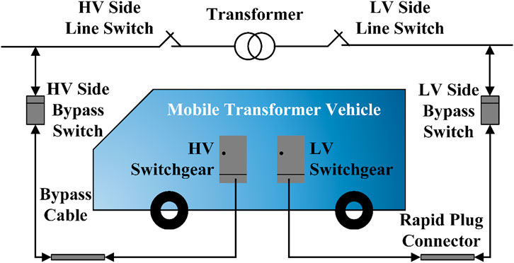
FIGURE 1. Schematic diagram of the mobile transformer vehicle bypass operation.
The workflow of interrupted maintenance or replacement of transformers is as follows (GB/T 34577-2017, 2017):
a) The mobile transformer vehicle and distribution lines should be connected with bypass cables and rapid plug connectors.
b) The HV side bypass switch should be closed.
c) The LV side bypass switch should be closed.
d) The mobile transformer vehicle and distribution transformer should be run in parallel for a period of time.
e) The LV sideline switch should be disconnected.
f) The HV sideline switch should be disconnected.
g) Maintenance or replacement of the transformer.
Overvoltage and overcurrent principle
The mobile transformer vehicle generates transient overvoltage and overcurrent when connected to the distribution network. Figure 2A shows the T-shaped equivalent circuit of the transformer, where R1 and X1σ denote the primary resistance and primary reactance of the transformer, respectively; R2 and X2σ denote the converted secondary resistance and secondary reactance of the transformer, respectively; Rm and Xm denote the excitation resistance and excitation reactance of the transformer, respectively; and ZL is the load converted to the primary side. When the transformer is unloaded, the load is infinite, and the equivalent circuit of the unloaded transformer at this time is shown in Figure 2B.

FIGURE 2. Equivalent circuit. (A) T-shaped equivalent circuit. (B) No-load transformer.
At this time, the equation of the magnetic chain of the no-load transformer is as follows (Fang et al., 2020b):
where Ψm is the steady-state magnetic chain amplitude, Ψr is the transformer remanence, α is the closing angle, and φ is the system impedance angle.
The differential equation of the magnetic chain of the no-load transformer is as follows (Fang et al., 2020b):
where i0 is the excitation current and Um is the system voltage amplitude.
From Eqs 1, 2, when the no-load transformer’s steady-state magnetic chain and the remanent magnetism of the superimposed magnetic chain are large, the transformer core will be saturated. Then, the excitation current surge will occur and cause overcurrent. Furthermore, due to the large harmonic component of the excitation current, resonant overvoltage may be generated between the inductive transformer and the capacitive system transmission line. In addition, when the mobile transformer vehicle is in the process of switching, if the current is not over the zero point of switching, there may be a large cut-off moment, generating the cut-off overvoltage.
Transient characteristics
Simulation model
A simulation model of a 10-kV distribution network and mobile transformer vehicle was established based on MATLAB/Simulink, as shown in Figure 3. The model mainly consists of six parts: 110 kV upper power supply, 110/10.5 kV main transformer, distribution line, distribution transformer, mobile transformer vehicle, and load. The parameters of each of these components are shown in Table 1.
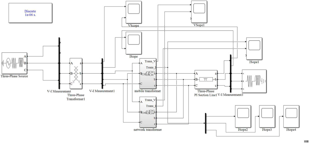
FIGURE 3. Distribution network simulation model.
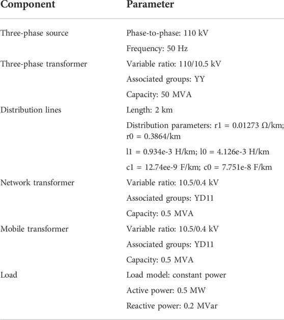
TABLE 1. Simulation component parameters.
The distribution transformer is set to 500 kVA, and the distribution transformer model is used, as shown in Figure 4.
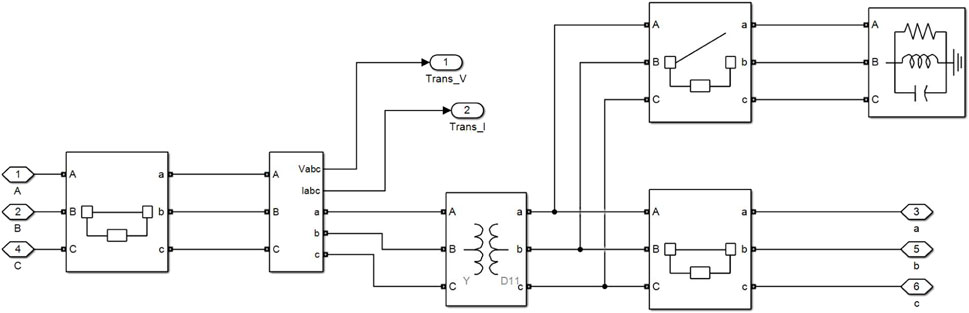
FIGURE 4. Distribution transformer model.
The distribution transformer mainly consists of a YD11-connected double-winding transformer and three circuit breaker modules, of which the left-side circuit breaker and the right-side lower circuit breaker control the distribution transformer to be connected or unconnected, and the upper right-side circuit breaker controls the timely discharge of the distribution transformer after it is unconnected to ensure the safety of personnel.
For the mobile transformer, since it can be equated to a distribution transformer, the model of the mobile transformer vehicle and the distribution transformer in the simulation model of this study is almost the same. Considering that the mobile transformer is equivalent to a no-load transformer in the grid-connected process, there may be remanent magnetism, so the mobile transformer model is set to a double-winding transformer considering core saturation, as shown in Figure 5.

FIGURE 5. Mobile transformer model.
Simulation setup
The simulation step is set to 1 μs, and the total simulation time is 0.5 s. According to the mobile transformer vehicle operation workflow described previously, the bypass switches for the mobile transformer vehicle and distribution transformer are set as shown in Tables 2, 3 by setting the closing and breaking times of the bypass switches during the simulation.
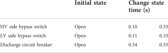
TABLE 2. Settings of the switch of the mobile transformer.
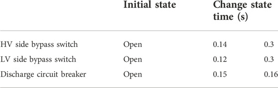
TABLE 3. Settings of the switch of the distribution transformer.
Simulation results
According to the settings, the voltage and current changes of the primary side and the user side of the distribution transformer during the grid connection of the mobile transformer vehicle were calculated using MATLAB/Simulink and shown in Figure 6.
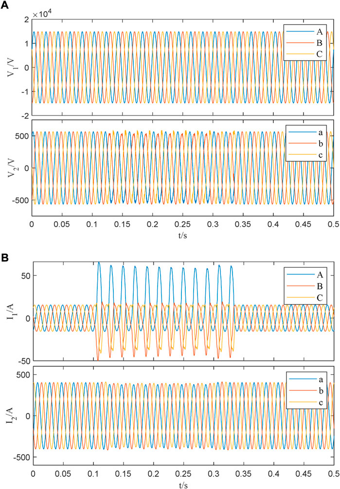
FIGURE 6. Voltage and current change of the primary side and the user side. (A) Comparison of voltage, (B) Comparison of current.
As shown in Figure 6, when the bypass switches of the mobile transformer vehicle are closed, a large excitation surge is generated on the primary side, but the degree of voltage change is small. As for the impact on the user side, both voltage and current signals have harmonics, which can affect the power quality of the users. The primary-side current and user-side voltage and current in one cycle after the mobile transformer vehicle is connected to the grid are analyzed in frequency-domain harmonics using the fast Fourier transform, and the results are shown in Table 4.
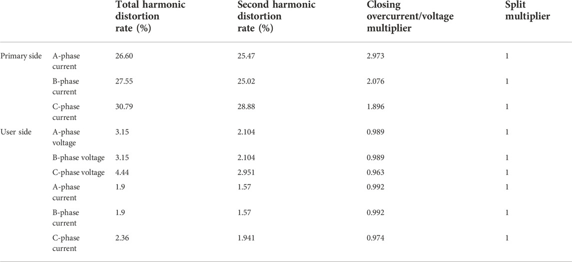
TABLE 4. Time-/frequency-domain analysis results.
Taking the A-phase current of the primary side and user-side as examples, the harmonic analysis results are shown in Figure 7.
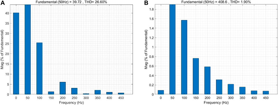
FIGURE 7. Harmonic analysis results. (A) Promary side, (B) User side.
As shown in Figure 7, when the mobile transformer vehicle is connected to the grid, the main harmonic component generated is the second harmonic. Therefore, the main object of harmonic analysis is the second harmonic content.
From the analysis of Table 4, it can be observed that the harmonic distortion rate of the primary side current and the overcurrent multiplier is very high. The total harmonic distortion rate of the user-side three-phase voltage is 3.15%, 3.15%, and 4.44%. The harmonic content of the C-phase voltage on the user side is close to the standard allowable limit (GB/T 14549-1993, 1993).
The calculated second harmonic current values of the primary-side three-phase current are 10.12 A, 7.02 A, and 8.1 A; the second harmonic current values of the user-side three-phase current are 6.42 A, 6.42 A, and 7.8 A, all of which do not exceed the standard limits.
Therefore, after the mobile transformer vehicle is connected to the grid, it generates an excitation inrush of the primary-side amplitude up to about 50 A, and the overcurrent multiplier exceeds 1.8 times when it is closed, and the overcurrent multiplier is smaller when it is separated, while the harmonic distortion rate also exceeds 20%, and the second harmonic is the main harmonic component. The overvoltage/current multiplier of the user-side voltage and user-side current is almost 1, and the harmonic distortion rate is 4%–5%, which is close to the standard limits, with certain risks.
Overcurrent suppression method
The overcurrent generated by the mobile transformer vehicle connection process can have an impact on the power quality of the grid. In this section, the suppression effects of two methods, adjustment of the closing angle method and the series closing resistance method, on overcurrent are analyzed to provide a theoretical basis for engineering applications.
Adjustment of the closing angle method
The current characteristics of phase A on the primary side and phase A on the user side were studied for closing angles from 0° to 90°, and the results are shown in Table 5.
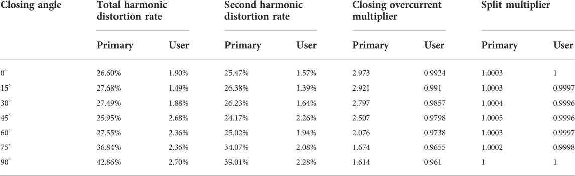
TABLE 5. Analysis results with different closing angles.
From the aforementioned analysis, it can be observed that by changing the closing angle, the closing overcurrent multiplier can be reduced, and when the closing angle is 90°, the closing overcurrent multiplier reaches the minimum, but the harmonic distortion rate increases. However, the method of changing the closing angle can only reduce the overcurrent multiplier of one or two phases because the essence of changing the closing angle is equivalent to shifting the three-phase voltage and current by an angle, and the calculation results also show that when the closing overcurrent multiplier of phase A decreases, the closing overcurrent multiplier of phases B and C may increase, so this method cannot improve the transient overcurrent situation well.
Series closing resistance method
Hang et al. (2022) proposed a method to reduce the overcurrent multiplier by connecting the closing resistors in series. Therefore, some simulations were carried out by stringing in resistors of different resistance values in the simulation platform, and the results are shown in Table 6.
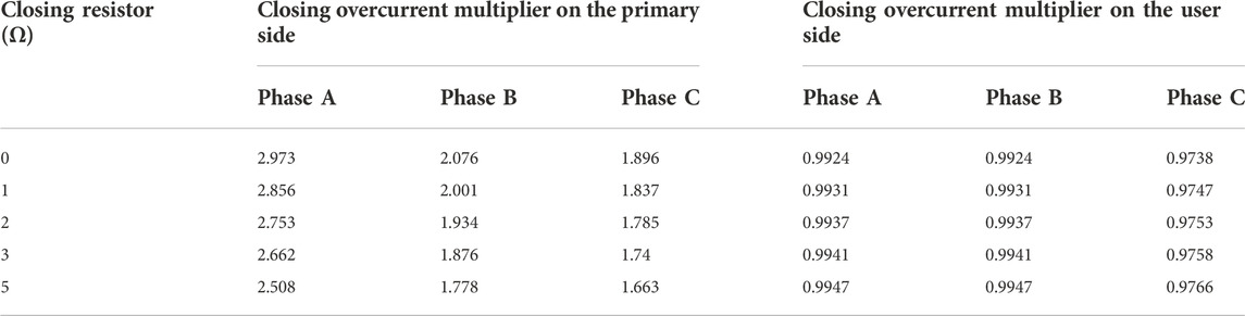
TABLE 6. Analysis results with the series closing resistance method.
As shown in Table 6, for the user-side current, the series resistance will increase the current amplitude. However, the effect is small, which is less than 1%. For the primary-side current, the overcurrent multiplier can be effectively reduced by the series closing resistance method. Moreover, the larger the resistance value of the series resistor is, the more the overcurrent multiplier will reduce. When the series resistance value is 5 Ω, the overcurrent multiplier can be reduced by up to 15%. This enhances the stability of the power line.
However, as the resistance value of series resistance increases, the loss of the power line will also increase, which will bring some economic loss. Therefore, in practical engineering applications, the resistance size of the series resistor should be evaluated in terms of the economy and overcurrent factor.
Discussion
To study the transient impact of the mobile transformer vehicles connected to the grid on the power system and the methods to suppress this impact, a distribution network simulation model of the mobile transformer vehicle bypass operation has been built on MATLAB/Simulink. Using this model, the overvoltage multiple, overcurrent multiple, and harmonic distortion rate of the primary side and the user side of the distribution system after the mobile transformer vehicles were connected to the distribution network have been analyzed. In addition, suppression effects of different closing angles and closing resistances on the aforementioned transient effects have been studied.
The simulation results show that after the mobile box transformer is incorporated into the distribution network system, the overvoltage/overcurrent multiple of the primary side will exceed 2.9 at most. At the same time, it will also bring more than 25% harmonic distortion rate, of which the second harmonic component accounts for the largest proportion. In addition, the second harmonic current can reach 10 A at most, which is close to the normal current of the distribution network. Such a large transient impact will not only cause greater line loss but also bring certain damage to the equipment of the distribution network.
To suppress these negative effects, two suppression methods have been studied. The simulation results of different closing angles show that when the closing angle is 0°, the aforementioned transient effect is the smallest. The simulation results of different closing resistances show that the larger the closing resistance is, the more obvious the suppression effect is. However, only increasing the closing resistance will also increase the line loss. Therefore, in the future, the closing resistance of mobile transformer vehicles when connected to the grid will be optimized by comprehensively considering the transient impact of distribution lines and economic operation. Moreover, more effective suppression measures need to be found to ensure the power quality of the distribution network while using the mobile transformer bypass operation method.
Conclusion
In this study, a model is built based on MATLAB/Simulink to model the process of grid connection of a mobile transformer vehicle. The simulation analyzed the current and voltage waveforms of the transient process of grid connection. Moreover, a combination of time-domain and frequency-domain analysis was used to analyze the transient overvoltage and overcurrent conditions of the grid connection, and the following conclusions were obtained:
1) The overcurrent multiplier is about two times, and the distortion rate of the voltage harmonics is close to the limit value specified in the standard, which reduces the power quality of the system and poses certain safety risks.
2) By changing the closing angle, the primary overcurrent multiplier of the mobile transformer vehicle can be reduced, but this cannot change the overcurrent multiplier of the three phases at the same time, and if the closing angle is adjusted too much, it may make the harmonic distortion rate of the current increase, thus affecting the power quality of the system.
3) By connecting the closing resistor in series, the three-phase overcurrent multiplier can be effectively reduced simultaneously to improve the power quality of the distribution lines. However, this method also has the problem of line losses.
This study mainly analyzes two methods to suppress the overcurrent of mobile transformer vehicle grid connection. Among them, the series resistance method can be studied further. In future work, the resistance value of the series resistance could be optimized by establishing a multi-objective optimization model, where the objective is to minimize the active network loss and overcurrent multiple (Feng et al., 2019).
Data availability statement
The original contributions presented in the study are included in the article/Supplementary Material; further inquiries can be directed to the corresponding author.
Author contributions
LZ: investigation, formal analysis, validation, supervision, and writing—original draft preparation. XF: writing—review and editing, project administration, and funding acquisition. XC: writing—review and editing and funding acquisition. HF: writing—review and editing and project administration. CB: writing—review and editing. YJ: writing—review and editing. SW: data curation, writing—review and editing, investigation, formal analysis, and validation.
Conflict of interest
Authors LZ, HF, and CB were employed by the Skill Training Center of State Grid Jiangsu Electric Power Co LTD; author XF was employed by Jiangsu Province Electric Power Co, LTD, Danyang Power Supply Branch.
The remaining authors declare that the research was conducted in the absence of any commercial or financial relationships that could be construed as a potential conflict of interest.
Publisher’s note
All claims expressed in this article are solely those of the authors and do not necessarily represent those of their affiliated organizations, or those of the publisher, the editors, and the reviewers. Any product that may be evaluated in this article, or claim that may be made by its manufacturer, is not guaranteed or endorsed by the publisher.
References
Cote, J., and Pelletier, M. (1995). Telemanipulator design and optimization software. Proc. Int. Soc. Opt. Photonics, 64–73. doi:10.1117/12.227948
Deng, W., and Pei, W. (2018). “Coordinated control technology of uninterrupted supply operation for medium voltage multi-terminal AC/DC interconnection system and its test platform,” in IEEE/PES Transm. Distribution Conf. Expo. (T&D), April 2018, Denver, CO, USA.
Dou, X., Hao, T., Wang, Y., and Zhao, J. (2021), Application of hot line work used for power distribution systems in region emergency power supply. Rural. Electrification 2021 (4), 12–14. doi:10.13882/j.cnki.ncdqh.2021.04.003
Fang, C., Long, J., Chen, C., Li, W., and Zhang, B. (2020). Controlled closing of unloaded transformer with ganged three-operated circuit breaker. High. Volt. Eng. 46 (3), 898–905. doi:10.13336/j.1003-6520.hve.20200331017
Fang, Y., Wang, L., Li, R., Gao, J., Song, B., and Liu, K. (2020). Modelling for switching impulse breakdown of live working gaps between equipotential worker and transmission towers. IET Gener. Transm. &. Distrib. 14 (7), 1271–1278. doi:10.1049/iet-gtd.2019.0789
Feng, P. A. N. G., Ma, D., and Yang, C. (2019). Research and application of 10 kV mobile high current load transfer system. Electr. Eng. (14), 104–105. doi:10.19768/j.cnki.dgjs.2019.14.046
Fu, X., Su, W., and Ge, C. (2020). “Bypass operation combined with short-bar insulation bridge operation method,” in International Conference on Intelligent Computing, Automation and Systems (ICICAS), Chongqing, China, Dec 2020.
Gao, J., Wang, L., Li, G., Fang, Y., Song, B., and Xiao, B., (2020). Discharge of air gaps during ground potential live-line work on transmission lines. Electr. Power Syst. Res. 187, 106519. doi:10.1016/j.epsr.2020.106519
Gb/T 34577-2017 (2017). Technical guide for by-pass working on distribution line. Natl. Stand. people’s, China.
Hang, P., Tong, Q., Wang, Y., Chen, Z., Yang, W., and Hu, D. (2022). Inrush current suppression strategy of converter transformer phase selection closing based on magnetic bias simulation. High. Volt. Enginnering, 1–11. doi:10.13336/j.1003-6520.hve.20211069
Hu, D., Wan, S., and Wang, H. (2016). Application and exploration of mobile box transformer car in rapid repair of distribution network. China Sci. Technol. Inf. (17), 55–56+13. doi:10.3969/j.issn.1001-8972.2016.17.020
Luo, J., Lan, J., Su, Y., Wang, H., Cai, Z., and Zhou, Y. (2009). Bypass technique of living-work on-site with 15 kV flexible power cable for power urgent repaired. High. Volt. Eng. 35 (4), 949–953. doi:10.13336/j.1003-6520.hve.2009.04.042
Sawada, J., Kusumoto, K., Maikawa, Y., Munakata, T., and Ishikawa, Y. (1991). A mobile robot for inspection of power transmission lines. IEEE Trans. Power Deliv. 6 (1), 309–315. doi:10.1109/61.103753
Sun, M., Qin, X., and Liu, T. (2021). Design and research of dual-voltage input mobile box-transformation vehicle. Autom. Appl. (10), 1 24–126. doi:10.19769/j.zdhy.2021.10.034
Sun, X. (2021). Styling design of highland electric engineering vehicles based on perceptual imagery. Xi'an Univ. Technol. doi:10.27391/d.cnki.gxagu.2021.000460
Wang, C., Lin, Z., Wei, Q., and Zhang, B. (2016). Live replacement of 10kV distribution transformer by bypass operation. Yunnan Electr. Power 44 (S2), 148–149.
Keywords: mobile transformer vehicle, bypass operation, live working, transient characteristics, stability analysis
Citation: Zhou L, Feng X, Chen X, Fu H, Bian C, Jing Y and Wu S (2023) Transient characteristics of mobile transformer vehicle bypass operation. Front. Energy Res. 10:1000049. doi: 10.3389/fenrg.2022.1000049
Received: 21 July 2022; Accepted: 31 October 2022;
Published: 13 January 2023.
Edited by:
Constantinos S. Psomopoulos, University of West Attica, GreeceReviewed by:
Amr S. Zalhaf, University of Electronic Science and Technology of China, ChinaEbrahim Badran, Mansoura University, Egypt
Copyright © 2023 Zhou, Feng, Chen, Fu, Bian, Jing and Wu. This is an open-access article distributed under the terms of the Creative Commons Attribution License (CC BY). The use, distribution or reproduction in other forums is permitted, provided the original author(s) and the copyright owner(s) are credited and that the original publication in this journal is cited, in accordance with accepted academic practice. No use, distribution or reproduction is permitted which does not comply with these terms.
*Correspondence: Shaocheng Wu, d3VzaGFvY2hlbmdAd2h1LmVkdS5jbg==