 Chao Xing
 Pengsong Li1,2
 Zihang Zhang
95% of researchers rate our articles as excellent or good
Learn more about the work of our research integrity team to safeguard the quality of each article we publish.
Find out more
ORIGINAL RESEARCH article
Front. Energy Res. , 16 March 2022
Sec. Smart Grids
Volume 9 - 2021 | https://doi.org/10.3389/fenrg.2021.820611
This article is part of the Research Topic Advanced Anomaly Detection Technologies and Applications in Energy Systems View all 64 articles
In view of the UHV multiterminal hybrid DC transmission system, the DC line protection with universal applicability, fast response speed, stability, and reliability is particularly important for its safe and economic operation. In this article, the boundary frequency characteristics of the UHV multiterminal hybrid DC transmission system are analyzed by considering the DC boundary of the rectifier side and inverter side, line frequency variation, and other factors. According to the fact that the boundary of the fault line has a strong attenuation effect on the high-frequency component of the transient current, a protection method based on the intrinsic mode energy entropy is proposed to distinguish the faults inside and outside. The criterion to initiate the protection is constructed by using the amplitude of the transient power; the fault direction criterion is constructed by using the positive and negative characteristics of the transient energy of the fault power detected by power direction elements on both sides of the T-zone; the fault pole selection criterion is constructed by using the ratio of low-frequency transient power changes of positive and negative poles. Finally, the Kun–Liu–Long line UHV three-terminal hybrid DC transmission system model is built on the PSCAD/EMTDC simulation platform, and a large number of simulation examples verify that the protection can operate reliably under different fault poles, fault positions, and transition resistances.
In recent years, large-scale new energy grid connection, regional power grid interconnection, and central load power supply have become hot issues at home and abroad, and it is urgent to build a DC network with higher power supply reliability on the basis of existing practical experience and theoretical research on DC transmission projects (Tang et al., 2013; He et al., 2017). Most of the traditional direct current transmission systems are two-terminal systems, which can only realize point-to-point power transmission whose remarkable feature is to realize AC collection–DC transmission–AC dispersion of electric energy (Wang et al., 2014). Compared with the traditional two-terminal DC transmission system, the UHV hybrid DC transmission system contains multiple sending terminals or receiving terminals, which can realize multipower supply and multi-drop power reception, and the operation mode is more flexible (Xu et al., 2013). The sending terminal is usually connected with a line-commutated converter (LCC), while the receiver is usually connected in parallel with a modular multilevel converter (MMC) with fault self-clearing capability (He et al., 2020). This structure makes comprehensive use of the advantages of low loss and good economy of conventional DC power transmission as well as flexible and fast control of flexible DC power transmission without commutation failure, such as Kun–Liu–Long line UHV multiterminal hybrid DC transmission demonstration project planned and constructed in China (Li et al., 2019).
The long distance of DC transmission lines and the complex environment of transmission corridors lead to a high fault rate (Li et al., 2021; Liu et al., 2020). When the DC fault occurs, it develops very quickly. The superposition of fault output of multiple converter stations in the UHV multiterminal hybrid DC transmission system makes the fault hazards such as line overcurrent more prominent (Muniappan, 2021). At present, the main protection widely used for the DC transmission lines is traveling wave protection (Shen and Raksincharoensak, 2021a). However, in actual operation, traveling wave protection is easily affected by factors such as inaccurate extraction of wave head information, selection of setting value, and high resistance ground fault, while its protection reliability is poor (Zheng et al., 2018). Xia et al. (2018) use the longitudinal impedance at both ends of the transmission line to propose a multiterminal line differential current protection, but there is a problem of too many measured values, and the communication time required increases when the line is long. Zhou et al. (2017) put forward a multiterminal flexible DC line protection scheme based on the voltage amplitude of a current-limiting reactor by using the characteristics of DC reactors as line boundary elements. However, there is a problem of poor transient resistance, and the multiterminal DC lines are interconnected by DC buses, and the T-zone structure formed by interconnection can be used directly with relatively few line boundary elements. Li et al. (2019) study the unique structure of T-zone in the parallel multiterminal hybrid DC transmission system and propose a fault direction discrimination principle based on the comparison of wavelet energy of fault current on both sides of T-zone. When applied to the three-terminal hybrid DC system, there is no need for interstation communication, but the selection of its setting value depends on the result of wavelet decomposition. In reference (Zhang Y. et al., 2021), the transient current fault components at the three ends of the T-junction bus are measured, and the correlation coefficient is calculated to serve as the basis for fault zone identification of the hybrid multiterminal DC transmission system. No interstation communication is required, but the noise tolerance is poor. Therefore, it is necessary to further study the DC line protection which is suitable for the UHV multiterminal hybrid DC transmission system and has fast response, stability, and reliability. Yang and Liu (2018) take the current mutation of each phase in the AC distribution network as the characteristic quantity, calculate its inherent modal energy entropy, and use the maximum modal energy maximum value for fault line selection. It is less affected by grounding the resistance and system structure and is more suitable for systems with complex structures. This principle provides a certain idea for the study of multiterminal hybrid HVDC transmission line protection.
In this article, the Kun–Liu–Long line UHV three-terminal hybrid DC transmission system is selected as the research object, and the boundary frequency characteristics of the rectifier side and the inverter side are analyzed theoretically. On this basis, a protection method is proposed to distinguish faults, inside and outside, based on the intrinsic mode energy entropy. The amplitude of transient power is used as the criterion to initiate the protection; the positive and negative characteristics of transient energy of fault power detected by power direction elements on both sides of the T-zone are used to identify the fault direction; the ratio of the variable quantity of low-frequency transient power of positive and negative poles is used to select the fault poles. The model of the Kun–Liu–Long line UHV three-terminal hybrid DC transmission system is built on the PSCAD/EMTDC simulation platform, and the effectiveness of the protection scheme is verified by a large number of simulation examples.
Figure 1 shows the simulation model of the Kun–Liu–Long line UHV three-terminal hybrid DC transmission system. The system adopts the true bipolar connection mode, with independent converter equipment, transmission lines, and control systems for both positive and negative poles. The LCC is used in the Kunbei Converter Station on the rectifier side, while the bipolar MMC with fault self-clearing capability is used in the Liubei Converter Station and Longmen Converter Station on the inverter side. The sending terminal Kunbei Converter Station and the receiving terminal Longmen Converter Station are connected to the bus bar in the receiving terminal Liubei Converter Station by line L1 and line L2, respectively (Yu et al., 2020). The T-zone is formed by the DC line L1 and L2 connected in parallel with the bus bar, and the protection devices M1 and M2 are installed on the left and right sides of the T-zone, respectively.
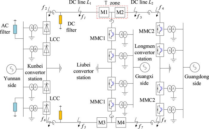
FIGURE 1. Structure diagram of the UHV three-terminal hybrid DC transmission system.
Because the rectifier side of the Kun–Liu–Long line UHV three-terminal hybrid DC transmission system adopts LCC, during the normal operation, due to the nonlinear characteristics of the converter, a large number of harmonic waves will be generated in the DC transmission line (Shen and Raksincharoensak, 2021b). Therefore, it is necessary to configure two smoothing reactors and two groups of triple-tuned DC filters at the head of the DC line L1 to suppress the harmonic current generated by the converter and injected into the DC line (Shen et al., 2017, Shen et al., 2020a). The smoothing reactors and DC filters together form the physical boundary on the rectifier side, as shown in Figure 2. The specific parameters of each component are shown in Table 1.
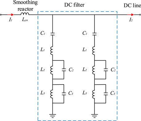
FIGURE 2. Line boundary on the Kunbei side line.
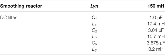
TABLE 1. Parameters of the smoothing reactor and DC filter.
In Figure 2, the symbol (I1) represents the transient current outside the protection zone of the DC line L1, while the symbol (I2) represents the transient current flowing into the DC line L1 after attenuation by the line boundary on the Kunbei side line. According to the parameters in Table 1, the expressions of equivalent impedance of the smoothing reactor and DC filter can be obtained, respectively, as follows:
In the formula, the symbol (
According to Eqs 1–3, the expression of the line boundary transfer function on the north side of Kunming can be further obtained as:
In order to quantitatively analyze the characteristics of
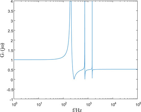
FIGURE 3. Amplitude frequency characteristics of the line boundary transfer function on the Kunbei side line.
It can be seen from Figure 3 that when 0 Hz < f ≤ 32 Hz
The MMC is used in the inverter side of the Kun–Liu–Long line UHV three-terminal hybrid DC transmission system. Because MMC uses the sub-module cascade to output multilevel stepped waves and the output wave form is of high quality, then only one current-limiting reactor is required at the end of the DC line L2 (Shen et al., 2020b, Shen et al., 2021a, Shen et al., 2021b). Because there is a ground capacitance between overhead lines and the ground, the current-limiting reactor and the ground capacitance of an overhead line at the end of the DC line L2 constitute the realistic boundary on the Longmen side. The boundary equivalent circuit on the Longmen side is shown in Figure 4.
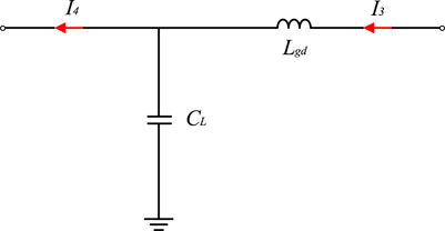
FIGURE 4. Line boundary on the Longmen side.
In Figure 4, the symbol (I3) represents the transient current outside the protection zone of the DC line L2, while the symbol (I4) represents the transient current flowing into the DC line L2 after being attenuated by the line boundary. The expression for defining the line boundary transfer function on the Longmen side is as follows:
In the formula,
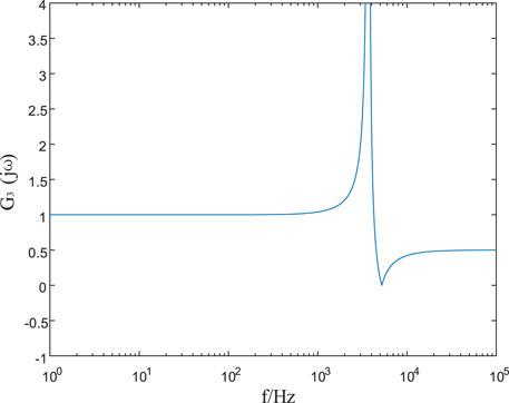
FIGURE 5. Amplitude frequency characteristics of the line boundary transfer function on the Longmen side.
It can be seen from Figure 5 that when 0Hz<f ≤ 434 Hz
From the aforementioned analysis of amplitude frequency characteristics of line boundary transfer functions on rectifier and inverter sides, it can be seen that high-frequency components of the transient current passing through boundary elements have obvious attenuation effect. When the fault occurs outside the DC line zone, the high-frequency energy of the fault transient current detected by the protection devices M1 and M2 is small due to the blocking effect of the line boundary. When the fault occurs in the DC line zone, the high-frequency signal is transmitted to the protection installation without obstruction, and the high-frequency energy of the fault transient current detected by the protection devices M1 and M2 is large. Therefore, the attenuation effect of high-frequency components of the transient current can be fully utilized, and the faults inside and outside the zone can be effectively distinguished.
Because a certain wavelet base needs to be selected in the wavelet transform, the selection of the wavelet base has a great influence on the whole wavelet analysis result (Yang et al., 2018, Yang et al., 2019a). Once the wavelet base is determined, it cannot be replaced in the whole analysis process. Even though the wavelet base may be the best in the whole situation, it may have poor effect in some parts (Yang et al., 2019b, Yang et al., 2021a).
In this article, complementary ensemble empirical mode decomposition (CEEMD) is selected as the signal processing method. CEEMD decomposes the line mode component of the fault transient current into several intrinsic mode functions (IMFs) and a residual margin according to the fluctuation or trend of different scales, and the intrinsic mode function reflects the fluctuation characteristics of the fault transient current in different time scales (Yang et al., 2021c, Yang et al., 2021b). The residual margin reflects the long-term trend characteristics of the fault transient current (Yeh et al., 2010). CEEMD does not need to predetermine or force a given basis function in advance but depends on the characteristics of the signal itself to decompose adaptively. The IMF components obtained generally have an obvious physical meaning, which is very suitable for the feature extraction of transient signals (Zhao, 2004).
Therefore, CEEMD is used to decompose the line mode component of the fault transient current inside and outside the DC line zone, and the decomposition result is shown in Eq. 6 (Ye and Liu, 2011):
In the formula, the symbol x(t) represents the original signal, cj(t) represents the intrinsic mode function, and rn(t) represents the residual term. c1(t), c2(t), …, and cn(t) are obtained after multiple decomposition of x(t), which have only a single frequency component at any time. They respectively represent n intrinsic mode function components which decrease from high frequency to low frequency, and the changing trend of rn(t) is similar to that of the original signal.
The intrinsic mode energy entropy is a measure that reflects the degree of energy distribution disorder of signals in various frequency bands (Zhu et al., 2020). It can be used to extract fault characteristics of the transient current. For the fault transient current, after CEEMD decomposition, the intrinsic mode energy of each frequency band in the decomposition scale on the i layer can be obtained as
By dividing the intrinsic mode function of each layer obtained by decomposition into n parts on the time axis and combining it with information entropy, we can define the intrinsic mode energy entropy H as (Ning et al., 2017):
In the formula,
The intrinsic mode energy entropy effectively combines complementary ensemble empirical mode decomposition, signal energy, and information entropy and effectively quantifies the discrete degree of energy distribution of the fault transient current with frequency (Guan and Zhang, 2011). It can be seen from Eq. 8 that the more uneven the distribution of energy of the fault transient current with frequency is, the smaller the intrinsic mode energy entropy is, and the greater the energy entropy is.
When the DC line L1 or the DC line L2 fails, the protection devices on both sides of the T-zone will detect larger transient current (
As there is the T-zone in the Kun–Liu–Long UHV three-terminal hybrid DC transmission system, protection devices are installed on the left and right sides of the zone; thus, directional components need to be added to identify where the faults are in an effective way. In this article, the power directional element as well as the positive and negative characteristics of the fault transient power is applied to identify the direction of faults. We select the time window of 2 ms after the protection is initiated, and we sum the transient power in the time window to form the transient energy. The formula is shown as follows:
The positive direction of the current is specified as the DC bus flowing to the line. It is assumed when a grounding fault emerges from the line on the left side of the T-zone. That means the faulty power supply with a reversed polarity is accessed at the fault point, and the transient current of the line flows to the fault point. The transient energy detected by the power directional element at the protection device (M1) is negative, while the one detected by the power directional element at the protection device (M2) is positive. When the grounding fault emerges from the line on the right side of the T-zone, the transient energy detected at the protection device (M1) is positive, but the one detected at the protection device (M2) is negative. Therefore, the specific discrimination results of the fault direction are as follows:
In the formula mentioned previously, the symbol (
According to the analysis of the frequency characteristic at the boundary on the Kunbei side line in Section 2.1, it shows that the line boundary has a strong attenuation effect on the high-frequency component of the transient current. As a fault occurs outside the DC line L2, the fault transient current reaches where the protection devices are installed after passing through the double attenuation of the boundary in the Kunbei side line and the DC line L1. At this moment, the high-frequency energy of the fault transient current detected by the protection device M1 is smaller. However, when a fault occurs in the DC line L1, the fault transient current reaches where the protection devices are installed only through the attenuation of the DC line. At this moment, the high-frequency energy of the fault transient current detected by the protection device (M1) is larger.
As a result, the line mode component of the fault transient current is decomposed by CEEMD (the Complementary Ensemble Empirical Mode Decomposition) before the intrinsic mode energy entropy of each frequency band is calculated, respectively. The energy entropy can be obtained through Eq. 8. When a fault occurs outside the DC line L1, the intrinsic mode energy entropy of the fault transient current is smaller. However, when a fault occurs in the DC line L2, the intrinsic mode energy entropy of the fault transient current is larger. In order to ensure the protection of the DC line L1, the minimum intrinsic mode energy entropy of faults in the zone is supposed to be greater than the maximum one of faults outside the zone. Thus, the criterion to identify the faults, inside and outside, on the left side of the T-zone is as follows:
In the formula mentioned previously, the letter N represents the number of sampling points, collected within the 2-ms time window after the protection is initiated, the letter K stands for the number of sampling points at the current moment, the symbol Krel refers to the reliable coefficient, and the symbol Hset1 is the threshold value of the intrinsic mode energy entropy of the protection device (M1). Given the interference of the signal noise and sampling errors, the reliability coefficient is equivalent to 1.3. In order to distinguish the faults inside and outside of the zone in a reliable manner, the value of Hset1 is selected with the most serious situation taken into account. The setting principle is that the high-resistance grounding fault in the DC line avoids the metallic grounding fault outside the line. The analysis of fault simulation data shows that, taking a certain margin into consideration, the threshold value of the intrinsic mode energy entropy is reasonably equivalent to 0.0008.
According to the frequency characteristic analysis of the boundary of the Longmen side line in Section 2.2, the boundary has a strong attenuation effect on the high-frequency component of the transient current. In the same way mentioned previously, the fault transient current line mode component on the right side of the T-zone is decomposed by CEEMD, thus calculating its intrinsic mode energy entropy. As there are faults emerging in and out of the DC line L2, the intrinsic mode energy entropy detected by the protection device (M2) is used to distinguish the faults in and out of the DC-zone. The criterion to identify faults, inside and outside, in the right area of the T-zone is expressed in the following:
In the formula mentioned previously, the letter N represents the number of sampling points, collected within 2-ms time window after the protection is initiated, the letter K stands for the number of sampling points at the current moment, the symbol Krel refers to the reliable coefficient, and the sign Hset2 means the threshold value of the intrinsic mode energy entropy of the protection device (M2). Taking the interference of the signal noise and sampling errors into consideration, the reliable coefficient is equivalent to 1.3. In order to distinguish the faults inside and outside of the zone in a reliable manner, the value of Hset2 is selected with the most serious situation taken into account. The setting principle is that the high-resistance grounding fault in the DC line L2 avoids the metallic grounding fault outside the line. The analysis of fault simulation data shows that, reflecting a certain margin, the threshold value of the natural modal energy entropy is reasonably equivalent to 0.001.
Normally, the positive and negative poles of the DC power transmission system operate symmetrically. When a fault occurs in the line, a protection device is needed to quickly and accurately identify the fault line as a way of ensuring that the non-fault pole line can normally transmit power without interference from it. Due to the electromagnetic coupling between the positive and negative poles of the line, the non-fault pole will produce an induced current when the grounding fault of the single pole occurs in the DC line. Amid the increase of the high-frequency component of the fault transient, the coupling effect between line poles is enhanced, narrowing the divide of high-frequency components between non-fault poles and fault ones. Therefore, the low-frequency component of the fault transient must be the option for the criterion of fault pole selection (Chu et al., 2017).
In this article, the fault transient power signal with a frequency below 1,000 Hz is extracted in a time window of 2 ms after the protection is operated. Also, the variation of the positive and negative transient power is viewed as the criterion of pole selection, and it is expressed in the following:
In the formula mentioned previously, the letter N represents the number of sampling points, collected within the time window of 2 ms after the protection is initiated (the letter i is equal to 1, 2, and so on.). The symbols
The analysis of fault simulation data suggests that, in order to make the protection devices against faults at any position in the zone, they can accurately select the poles; so, the setting value (Kset1) of the fault positive pole is equivalent to 150, while the value of the fault negative pole is equivalent to 60. Comparing the ratio (K) of the positive transient power variation to the negative one with both setting values Kset1 and Kset2, the result of the criterion is as follows:
According to the aforementioned analysis, the transient scheme to protect the UHV multiterminal hybrid DC transmission line based on intrinsic mode energy entropy is introduced, by virtue of the criterion to initiate the protection, identify the direction of faults, to protect the criterion of fault pole selection inside and outside the zone. The scheme is shown in Figure 6. First, the protection device detects the transient current (
1) Assuming that the transient energy detected by the power directional element at the protection device (M1) is negative and the one detected by the power directional element at the protection device M2 is positive, and there is a malfunction emerging on the left side of the T-zone. The line mode component of the fault transient current on the left side of the T-zone has undergone the decomposition through CEEMD as it seeks to calculate the intrinsic mode energy entropy of the fault transient current. The moment the minimum intrinsic mode energy entropy of the fault in the DC line L1 is greater than the threshold value (Hset1), there is a fault occurring on the left side of the T-zone. That means the protection device (M1) works. On the contrary, when the maximum intrinsic mode energy entropy of the fault outside the DC line L1 is less than the threshold value (Hset1), there is a fault outside the left side of the T-zone. Under this condition, the protection device (M1) does not operate.
2) Provided that the transient energy detected by the power directional element at the protection device (M1) is positive, and the one detected by the power direction element at the protection device (M2) is negative, and a fault must occur on the right side of the T-zone. The line mode component of the fault transient current on the right side of the T-zone is decomposed by CEEMD as a way of calculating its intrinsic mode energy entropy. When the minimum intrinsic mode energy entropy of potential faults in DC line L2 is greater than the threshold value (Hset2), the right side of the T-zone is dysfunctional. That makes the protection device M2 to operate. On the contrary, when the maximum intrinsic mode energy entropy of the fault outside the DC line L2 is less than the threshold value (Hset2), the fault occurs outside the right side of the T-zones. In this context, the protection device M2 does not operate.
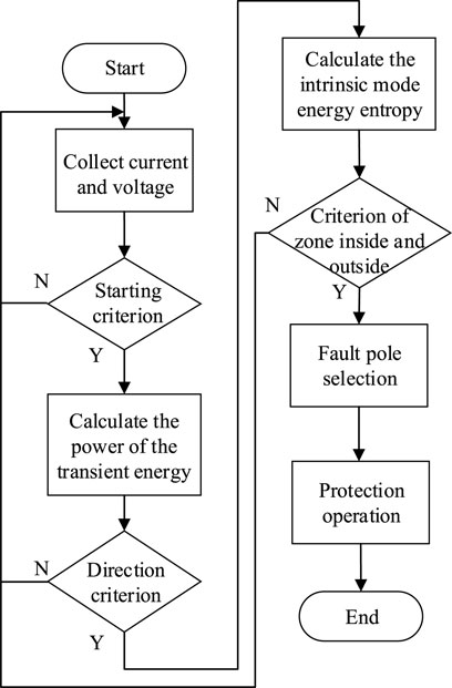
FIGURE 6. Flow chart of the protection.
In the final analysis, the low-frequency component of the fault transient power is extracted to identify in which pole the malfunction appears through the ratio (K) of the positive transient power variation to the negative one.
In light of the engineering parameters of the Kun–Liu–Long line UHV three-terminal hybrid DC transmission system, the simulation model of the system as shown in Figure 1 is established in the simulation platform PSCAD/EMTDC (Power Systems Computer-Aided Design/Electromagnetic Transients including DC). The main parameters of the simulation model are shown in Table 2.
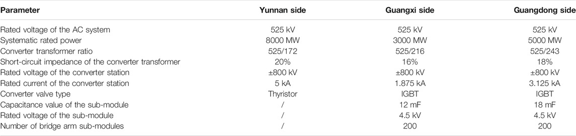
TABLE 2. Main parameters of the simulation model.
In the Kunbei Converter Station, the main connection mode, featured by two unipolar 12-pulse converter units in series, is adopted. Each converter unit bears 400 kV voltage, and the unipolar series voltage is distributed according to (400 plus 400) kV. The constant current control is handled. The Liubei and Longmen converter stations are connected in series with two MMC units in a single pole. The two units are connected in series to form high- and low-valve groups, and the single-pole series voltage is distributed according to (400 plus 400) kV. Each converter chain unit inside the MMC applies the main connection mode that is mixing and cascading half-bridge and full-bridge in proportion. The upper and lower bridge arms are connected to 200 sub-modules at any time, with some left behind. The output voltage of a single converter valve is maintained at 400 kV.
In Figure 1, the total length of the DC line L1 is 932 km, with an average soil resistivity of 1,750 along the line, whereas the total length of the DC line L2 is 554 km, with an average soil resistivity of 2,500 along the line. Those where both adopt the frequency-dependent (Phase) model options f1, f3, f5, and f7 stand for the location of faults on the positive and negative DC line L1 and the DC line L2, the location of faults falls outside the positive and negative DC lines. The protection range of the protection device M1 includes the whole line L1, whereas the protection device M2 responses to the whole line L2.
Under the amplitude frequency characteristics of the boundary transfer function gained from Sections 2.1, 2.2, in this article, the sampling frequency of 50 kHz is adopted, and the time window of 2 ms is taken after the protection is started. The fault appears at 1.1 s and lasts for 0.1 s.
The faults, inside and outside of the zone, can be distinguished by the value of intrinsic mode energy entropy in an effective way. For that to happen, the grounding fault at the point f1, 932 km away from the protection device on the left side of the T-zone, and another one at the point f2, outside the DC line L1 on the left side of the T-zone, are viewed as typical examples in this article. The intrinsic mode energy entropy that is calculated is made to slide in the sampling window of 2 ms. By doing so, the curve, showed in Figure 7, in which the intrinsic mode energy entropy changes with time, is accessible.
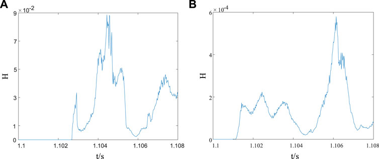
FIGURE 7. Graph of intrinsic mode energy entropy changing with time. (A) Grounding fault of the point f1 in the DC line L1; and (B) grounding fault of the point f2 outside the DC line L2.
From Figure 7, the intrinsic mode energy entropy responses to the overall amplitude of the signal in a less sensitive manner. If faults occur inside and outside the DC line L1, the intrinsic mode energy entropy at the position where the protection devices are installed will suddenly change. Due to the attenuation effect of the line boundary on the high-frequency component of the fault transient, the intrinsic mode energy entropy in the DC line is obviously larger than that of outside the line.
With regard to the transient protection scheme of the UHV multiterminal hybrid DC transmission line based on intrinsic mode energy entropy, the simulation verification of the protective principle is conducted, taking different positions of the fault anode and cathode (the points f2 and f6 outside the DC line L1, the points f1 and f5 at 932, 466, and 0 km away from the protection device on the left of the T-zone, the points f3 and f7 at 0, 277, and 554 km away from the protection device on the right side of the T-zone, and the points f4 and f8 outside the DC line L2) as well as various transition resistances (0.01
From the simulation results in Tables 3, 4, the location of faults and the transition resistance are expanding, and the energy entropy of the natural mode is decreasing. The entropy values, however, of faults inside and outside the zone are still quite different. That said, the protection is not affected and resistant to the transition resistance to some extent. In this article, the transient protection scheme of the UHV multiterminal hybrid DC transmission line based on the intrinsic mode energy entropy boasts a good performance on protection and high reliability. That means the protection devices (M1) and (M2) can operate in a reliable way as they are in face of different fault poles, positions, and transition resistances.

TABLE 3. Result of protecting the positive pole from faults.
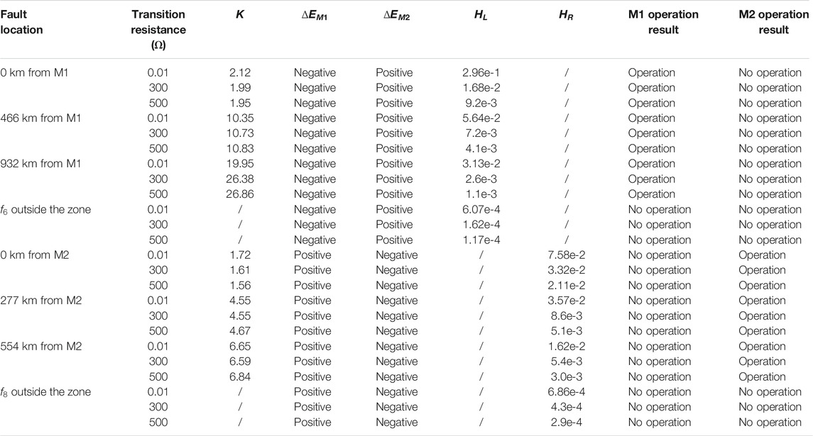
TABLE 4. Result of protecting the negative pole from faults.
Regarding to the analysis and summary of boundary frequency characteristics of the Kun–Liu–Long UHV three-terminal hybrid DC transmission line, and on the basis of the complementary ensemble empirical mode decomposition (CEEMD), the intrinsic mode energy entropy, and the transient power polarity, a transient protection scheme, suitable for the UHV multiterminal hybrid DC transmission system, is put forward in this article. The protection scheme handles the positive and negative characteristics of transient energy of the fault power detected by power directional elements on both sides of the T-zone to identify the fault direction. As the boundary of the fault line is capable of reducing the high-frequency component of the transient current in a strong manner, the value of the intrinsic mode energy entropy is applied to further distinguish the faults inside and outside the zone. After the analysis mentioned previously, the following conclusions are attainable:
1) The transient current high-frequency component has obviously attenuated as it passes through the line boundary element, but the potential of the attenuation is supposed to be fully tapped to effectively distinguish the faults in and out of the zone.
2) The attenuation characteristics of high-frequency components of the transient current has limitation as it distinguishes the fault on the left and right sides of the T-zone of the UHV multiterminal hybrid DC transmission system; so, the power directional components can be used for identifying the direction of faults.
3) The protection scheme can quickly remove faults, without exchanging synchronous current information between converter stations.
4) A large amount of the simulation results show that the transient protection of UHV multiterminal hybrid DC transmission lines based on intrinsic mode energy entropy can operate reliably under different fault poles, fault positions, and transition resistances. That empowers it a fine value for practical application.
The original contributions presented in the study are included in the article/Supplementary Material; further inquiries can be directed to the corresponding author.
CX was responsible for providing ideas and methods and providing an experimental platform. SC was responsible for deriving formulas, reviewing, and verifying. PL was responsible for model building, simulation, data analysis, and manuscript writing. GB, JC, and ZZ wrote the sections of the manuscript. All authors participated in the reading and approved the submitted version.
The research is funded by the National Natural Science Foundation of China (52067009).
Author CX is employed by Electric Power Research Institute, Southern Power Grid Yunnan Electric Power Co., Ltd. Author SC works at Kunming University of Science and Technology.
All the authors declare that the research was conducted in the absence of any commercial or financial relationships that could be construed as a potential conflict of interest.
All claims expressed in this article are solely those of the authors and do not necessarily represent those of their affiliated organizations, or those of the publisher, the editors, and the reviewers. Any product that may be evaluated in this article, or claim that may be made by its manufacturer, is not guaranteed or endorsed by the publisher.
Chen, S., Yang, H., Guihong, B., and Zhao, S. (2021). Boundary Frequency Characteristic Study of Traction Network in Continuous Co-phase at Traction Power Supply System [J]. Electric Power Automation Equipment 41 (06), 192. doi:10.16081/j.epae.202102026
Chu, X., Wang, L., Wang, H., and Song, G. (2017). Analysis of Inter-pole Coupling Effect and Faulty Pole Selection for HVDC Transmission Line [J]. Electric Power Automation Equipment 37 (04), 140. doi:10.16081/j.issn.1006-6047.2017.04.021
Guan, J., and Zhang, J. (2011). Weak Target Detection Based on Intrinsic Mode Energy Entropy. J. Electro. Inf. Techn. 33 (10), 2494–2499. doi:10.3724/sp.j.1146.2011.00147
He, J., Chen, K., Li, M., Luo, Y., Liang, X., and Xu, Y. (2020). Review of protection and Fault Handling for a Flexible DC Grid[J]. Prot. Control. Mod. Power Syst. 5 (1), 5–15. doi:10.1186/s41601-020-00157-9
He, J., Li, B., Li, Y., Qiu, H., Wang, C., and Dai, D. (2017). A Fast Directional Pilot Protection Scheme for the MMC-Based MTDC Grid [J]. Proc. CSEE 37 (23), 6878. doi:10.13334/j.0258-8013.pcsee.161573
Li, H., Zhang, K., Wang, G., Huang, D., Li, M., and Guo, Z. (2019). Fault Area Discrimination Method for Parallel Multi-Terminal Hybrid HVDC Line [J]. Automation Electric Power Syst. 43 (04), 119. doi:10.7500/AEPS20180615004
Li, Z., Jiang, W., Abu-Siada, A., Li, Z., Xu, Y., and Liu, S. (2021). Research on a Composite Voltage and Current Measurement Device for HVDC Networks. IEEE Trans. Ind. Electron. 68 (9), 8930–8941. doi:10.1109/tie.2020.3013772
Liu, Y., Yang, N., Dong, B., Wu, L., Yan, J., Shen, X., et al. (2020). “Multi-Lateral Participants Decision-Making: A Distribution System Planning Approach with Incomplete Information Game,” in IEEE Access, 8, 88933–88950. doi:10.1109/access.2020.2991181
Muniappan, M. (2021). A Comprehensive Review of DC Fault protection Methods in HVDC Transmission systems[J]. Singapore: Springer Singapore PTE LTD.
Ning, L., Tai, N., Zheng, X., and Huang, W. (2017). Research on MMC-HVDC Transmission Line Protection Scheme Based on One Terminal Transient Current [J]. Proc. CSEE 37 (17), 5010
Shen, X., Ouyang, T., Khajorntraidet, C., Li, Y., Li, S., and Zhuang, J. (2021b). Mixture Density Networks-Based Knock Simulator. Ieee/asme Trans. Mechatron. 1, 1. doi:10.1109/TMECH.2021.3059775
Shen, X., Ouyang, T., Yang, N., and Zhuang, J. (2021a). Sample-based Neural Approximation Approach for Probabilistic Constrained Programs. IEEE Trans. Neural Netw. Learn. Syst., 1–8. doi:10.1109/TNNLS.2021.3102323
Shen, X., and Raksincharoensak, P. (2021a). “Pedestrian-aware Statistical Risk Assessment,” in IEEE Transactions on Intelligent Transportation Systems 99, 1–9. doi:10.1109/TITS.2021.3074522
Shen, X., and Raksincharoensak, P. (2021b). Statistical Models of Near-Accident Event and Pedestrian Behavior at Non-signalized Intersections. J. Appl. Stat., 1–21. doi:10.1080/02664763.2021.1962263
Shen, X., Zhang, X., Ouyang, T., Li, Y., and Raksincharoensak, P. (2020b). Cooperative Comfortable-Driving at Signalized Intersections for Connected and Automated Vehicles. IEEE Robot. Autom. Lett. 5, 6247–6254. doi:10.1109/LRA.2020.3014010
Shen, X., Zhang, Y., Sata, K., and Shen, T. (2020a). Gaussian Mixture Model Clustering-Based Knock Threshold Learning in Automotive Engines. Ieee/asme Trans. Mechatron. 25 (6), 2981–2991. doi:10.1109/TMECH.2020.3000732
Shen, X., Zhang, Y., Shen, T., and Khajorntraidet, C. (2017). Spark advance Self-Optimization with Knock Probability Threshold for Lean-Burn Operation Mode of SI Engine. Energy 122, 1–10. doi:10.1016/j.energy.2017.01.065
Tang, G., and He, Z., and (2013). Research, Application and Development of VSC-HVDC Engineering Technology [J]. Automation Electric Power Syst. 37 (15), 3
Wang, J., Fu, C., Hu, M., Zhang, D., and Han, H. (2014). Discussion on the Protection in Parallel-type Multi-Terminal HVDC Systems [J]. Proc. CSEE 34 (28), 4923. doi:10.13334/j.0258-8013.pcsee.2014.28.020
Xia, J., Qin, R., Qian, H., Gao, S., Jiao, Z., and He, S. (2018). Study on Improved Algorithm in Differential protection of Multi-Terminal Line [J]. Electric Power Automation Equipment 38 (12), 140–147. doi:10.16081/j.issn.1006-6047.2018.12.021
Xu, Z., Hu, Y., and Fu, C. (2013). Control Strategy and Fault Characteristics of Parallel MTDC Transmission Systems [J]. High Voltage Eng. 39 (11), 2721. doi:10.3969/j.issn.1003-6520.2013.11.021
Yang, N., Huang, Y., and Hou, D. (2019b). Adaptive Nonparametric Kernel Density Estimation Approach for Joint Probability Density Function Modeling of Multiple Wind Farms[J]. Energies 12. doi:10.3390/en12071356
Yang, N., Ye, D., Zhou, Z., Cui, J., Chen, D., and Wang, X. (2018). Research on Modelling and Solution of Stochastic SCUC under AC Power Flow Constraints[J. IET Generation, Transm. Distribution 12 (15), 3618. doi:10.1049/iet-gtd.2017.1845
Yang, N., Huang, Y., Hou, D., Liu, S., Ye, D., Dong, B., et al. (2019a). Adaptive Nonparametric Kernel Density Estimation Approach for Joint Probability Density Function Modeling of Multiple Wind Farms. Energies 12, 1356. doi:10.3390/en12071356
Yang, N., Liu, S., Deng, Y., and Xing, C. (2021c). An Improved Robust SCUC Approach Considering Multiple Uncertainty and Correlation. IEEJ Trans. Elec Electron. Eng. 16, 21–34. doi:10.1002/tee.23265
Yang, N., Yang, C., Wu, L., Shen, X., Jia, J., Li, Z., et al. (2021a). “Intelligent Data-Driven Decision-Making Method for Dynamic Multi-Sequence: An E-Seq2Seq Based SCUC Expert System,” in IEEE Trans. Ind. Inf., doi:10.1109/TII.2021.3107406
Yang, N., Yang, C., Xing, C., Ye, D., Jia, J., Chen, D., et al. (2021b). Deep Learning‐based SCUC Decision‐making: An Intelligent Data‐driven Approach with Self‐learning Capabilities. IET Gener. Transm. Distrib. 1, 12. doi:10.1049/gtd2.12315
Yang, X., and Liu, W. (2018). A New Line Selection Method Based on Intrinsic Mode Energy of Phase Current Change [J]. J. Electric Power Sci. Techn. 33 (04), 147
Ye, L., and Liu, P. (2011). Combined Model Based on EMD-SVM for Short-Term Wind Power Prediction [J]. Proc. CSEE 31 (31), 102. doi:10.1016/S1872-5805(11)60064-4
Yeh, J. R., Shieh, J. S., and Huang, N. E. (2010). Complementary Ensemble Empirical Mode Decomposition: a Novel Noise Enhanced Data Analysis Method [J]. Adv. Adaptive Data Anal. 2 (2), 26. doi:10.1142/s1793536910000422
Yu, X., Wang, Y., Zhang, Q., Wang, Y., Dong, Y., and Gan, Z. (2020). Power Transfer Strategy of Parallel Three-Terminal Hybrid UHVDC Transmission System [J]. Automation Electric Power Syst. 44 (23), 150. doi:10.7500/AEPS20200601004
Zhang, Y., Ma, H., Li, T., Liu, Z., and Feng, K. (2016). HVDC Line Protection Based on the Mutant Power through Kaiser Window [J]. High Voltage Eng. 42 (01), 19. doi:10.13336/j.1003-6520.hve.2016.01.003
Zhang, L., Xie, Y., Ye, J., Xue, T., Cheng, J., and Li, Z. (2021). Intelligent Frequency Control Strategy Based on Reinforcement Learning of Multi-Objective Collaborative Reward Function [J]. Front. Energy Res. 9, 760525. doi:10.3389/fenrg.2021.760525
Zhang, Y., Chen, K., Luo, Y., Liang, C., Ning, J., and Nie, M. (2021). Hybrid Multi-Terminal HVDC Transmission Line Protection Based on Transient Current Correlation Coefficient [J]. Electric Power Construction 42 (05), 113–121. doi:10.12204/j.issn.1000-7229.2021.05.012
Zheng, J., Wen, M., Qin, Y., Chen, Y., and Yu, B. (2018). A Novel Differential Protection Scheme with Fault Line Selection Capability for HVDC Transmission Line [J]. Proc. CSEE 38 (15), 4350. doi:10.13334/j.0258-8013.pcsee.171960
Zhou, J., Zhao, C., Li, C., Xu, J., and An, T. (2017). Boundary Protection Scheme for Multi-Terminal Flexible DC Grid Based on Voltage of DC Reactor [J]. Automation Electric Power Syst. 41 (19), 89. doi:10.7500/AEPS20170331005
Keywords: the multiterminal hybrid DC, boundary frequency characteristics, the intrinsic mode energy entropy, the T-zone, the transient power
Citation: Xing C, Li P, Bi G, Chen S, Chen J and Zhang Z (2022) Multiterminal Hybrid DC Line Protection Based on Intrinsic Mode Energy Entropy. Front. Energy Res. 9:820611. doi: 10.3389/fenrg.2021.820611
Received: 23 November 2021; Accepted: 23 December 2021;
Published: 16 March 2022.
Edited by:
Xun Shen, Tokyo Institute of Technology, JapanReviewed by:
Zhenhua Li, China Three Gorges University, ChinaCopyright © 2022 Xing, Li, Bi, Chen, Chen and Zhang. This is an open-access article distributed under the terms of the Creative Commons Attribution License (CC BY). The use, distribution or reproduction in other forums is permitted, provided the original author(s) and the copyright owner(s) are credited and that the original publication in this journal is cited, in accordance with accepted academic practice. No use, distribution or reproduction is permitted which does not comply with these terms.
*Correspondence: Shilong Chen, Y2hlbnNoaWxvbmczQDEyNi5jb20=
Disclaimer: All claims expressed in this article are solely those of the authors and do not necessarily represent those of their affiliated organizations, or those of the publisher, the editors and the reviewers. Any product that may be evaluated in this article or claim that may be made by its manufacturer is not guaranteed or endorsed by the publisher.
Research integrity at Frontiers
Learn more about the work of our research integrity team to safeguard the quality of each article we publish.