 Zhengdian Xu
 Hong Li*
 Pan Tang
95% of researchers rate our articles as excellent or good
Learn more about the work of our research integrity team to safeguard the quality of each article we publish.
Find out more
ORIGINAL RESEARCH article
Front. Energy Res. , 13 January 2022
Sec. Process and Energy Systems Engineering
Volume 9 - 2021 | https://doi.org/10.3389/fenrg.2021.817262
This article is part of the Research Topic Design, Simulation and Optimization of Hydraulic Machinery View all 25 articles
To solve the problems of higher energy consumption and lower intelligence of traditional hard hose travelers, a new hard hose traveler with the function of electric drive and self-propelled is developed in this paper. The operational energy consumption of a reel and a polyethylene tube is an important part of hard-hose traveler energy consumption. In this paper, based on the JP50-180 hard hose traveler, the required pulling force and energy consumption at the reel and tube operation are theoretically and experimentally obtained. The aforementioned provides support for reducing energy consumption in the future. The influencing factor that affects the energy consumption of the reel rotation is the tube length, and the influencing factors that affect the energy consumption of the tube sliding are the ground slope, soil moisture content, and tube length. A calculation model for the dynamic change of the pulling force and energy consumption of the reel and tube operation is proposed in this study. Through theoretical analysis, maximum pulling tension and cumulative energy consumption requirements for the for reel rotation are 278.6 N and 15120.83 J, respectively. Furthermore, the requirements for the tube sliding are 1372.86 N and 123,456.96 J. Through test analysis, the maximum pulling tension for the tube sliding is between 1258.3 N and 1773.3 N, while the maximum pulling tension for reel rotation is 285.05 N. Under the same influencing factors, the deviation rates between theoretical and testable energy consumption for the reel rotation and tube sliding are 2.3 and 8.3%, respectively. The pulling force and cumulative energy consumption required for the reel rotation and tube sliding both increase with an increase in their influencing factors. The operating costs of the tube one-time unrolled are approximately 0.0185 CNY. Combined with the mobile resistance of the electric tracked vehicle, the power configuration of this new hard hose traveler is provided by two servo motors with a power of 5500 W each.
The traditional hard hose traveler is a continuous mobile irrigation machine (Ge, 2018), that is driven by a water turbine and has the highest energy consumption of all irrigation machines (Keller and Bliesner, 1990; Burt et al., 1999). Its operational energy consumption is mainly composed of the driving energy consumption, sprinkler irrigation energy consumption (Rochester and Hackwell, 1991), pressure loss in the polyethylene tube (Rochester et al., 1990; Tang et al, 2017). Under typical working conditions, it is found that the former two account for 7–12% and 50–70% of 1operational energy consumption, respectively. The latter approximately accounts for 18–43% of energy consumption (Oakes and Rochester, 1980). The driving energy is mainly consumed by the water turbine, gearbox transmission, reel rotation, friction between polyethylene tube and the ground and friction between the irrigation cart and the ground (Ge, 2018), which has a lower energy conversion efficiency (Li et al., 2019). Both numerical simulation (Biolan et al., 2012) and actual measurement (Tang Y et al., 2014; Yuan et al., 2014) results showed that the energy conversion efficiency of the water turbine is only 1.5–20.0%. Although the driving energy consumption accounts for a relatively lower proportion of the operating energy consumption of traditional hard hose travelers, the long-term operating costs are affected by the driving energy consumption of the water turbine (Ge et al., 2020). Therefore, studying the reduction of driving energy consumption is still a significant for the hard hose traveler.
In addition to the water turbine driven by the traditional hard hose traveler, electric motors (Yang, et al., 2018) and hydraulic motors (Pan, 2019) can also be used. Among them, the highest energy conversion efficiency is obtained for driven electric motors. The driving efficiency of ordinary motors is generally 70–80%. However, brushless DC motors can reach more than 80% of energy through batteries or solar energy (Tang et al., 2018). To directly reduce operating costs, energy consumption should be lowered. In addition, achieving the applicability of the hard hose traveler in a variety of fields (such as mountain slopes and small and medium-sized irregular fields) and more application functions (such as fertilization, spraying and short distance transport) is also an effective way. In other words, a variety of agricultural machinery or more models of the hard hose traveler can be used to reduce early purchasing costs. Consequently, a design concept of the new hard hose traveler is proposed in this paper. Within the model, the electric tracked vehicle is used to load the sprinkler for irrigation. Moreover, part of the structural design and the principle of retracting and placing polyethylene tubes are based on the traditional hard hose traveler. The electric tracked vehicle is characterized by fiercer climbing and more flexible maneuvering. The aforementioned could solve the irrigation problems of the sloping field mountain area and irregular fields. Moreover, it could improve the applicability of the hard hose traveler in a variety of fields. In addition, the electric tracked vehicle could also achieve multi-functional applications of fruit and vegetable management in the greenhouse (Cui et al., 2019; Xu et al., 2022), picking (Zhang, 2016), and short distance transport (Li, 2018).
In this paper, to reduce the energy consumption of traditional hard hose traveler and develop a new hard hose traveler, exploring the energy consumption of reel and polyethylene tube operation is one of the key parameters. This is of particular importance since not many investigations exist on the topic. Currently, the study on energy consumption of traditional hard hose travelers is mainly focused on the pressure loss in the tube. Under the wound state of the tube, the additional value of the pressure loss is shown in Eq. 1 (Rochester et al., 1990). Within a certain flow range, the pressure loss of the curved polyethylene tube under a specific pipe diameter and different curvature radii were measured, and the obtained specific law is shown in Eq. 2 (Zhang and Wang, 2005). Characteristics of secondary flow in the polyethylene tube wound were numerically analyzed by multiple schemes. The regression equation of the friction coefficient in the wound tube was then established (Eq. 3) (Tang L et al., 2014).
where hb is the additional value of the pressure loss in the tube, mm; Kb is the coefficient of the wound tube; V is the liquid flow velocity in the tube, m s−1; g is the acceleration due to gravity, m s−2; hbzw is the pressure loss in the tube, mm; fb is the coefficient of the pressure loss in the tube; S is the length of the tube, m; Q is the flow rate in the tube, m3 h−1; m is the index of flow rate; fCT is the friction coefficient in the wound tube; Re is Reynolds number in the tube; r is the inner radius of the tube, mm; R0 is the radius of the reel, mm.
The energy consumption of reel rotation is affected by the length of the tube and the friction coefficient between the machines (Zhang et al., 2015). The energy consumption of the tube sliding is affected by factors such as the ground slope, soil moisture content, and tube length (GB/T 21400.1- 2008, 2008). The aforementioned two types of energy consumption are one of the foundations of power configuration in the proposed hard hose traveler. Moreover, power configuration is the core of electric tracked vehicles (Fan, 2017). Therefore, energy consumption analysis is a very important parameter for the design of a new hard hose traveler.
In this paper, the required pulling force and energy consumption of reel and polyethylene tube operation are analyzed theoretically and experimentally. Furthermore, the aforementioned is combined with the running energy consumption of the electric tracked vehicle. Together, these parameters represent a basis for power configuration design and optimization of a new hard hose traveler.
The new hard hose traveler is based on the structure design of the traditional hard hose traveler. Moreover, it is controlled and operated by a remote terminal. Its structure mainly includes a reel, polyethylene tube, electric tracked vehicle, sprinkler and motor-gearbox system, as shown in Figure 1. The reel is used to store the polyethylene tubes. The electric tracked vehicle is used to pull out the tubes in the reel and load the sprinkler. The motor-gearbox system is used to recycle the tubes, which are used to replace the water turbine and turbine gearbox of the traditional hard hose traveler. During the sprinkler irrigation operation, the reel is stored at the water source, and an electric tracked vehicle is located relatively far from the reel. Furthermore, the tubes are pulled out to achieve mobile sprinkler irrigation. At the end of the sprinkler irrigation operation, the tubes are separated from the electric tracked vehicle. The motor-gearbox system rotates the reel which recycles the tubes. Consequently, the electric tracked vehicle is transferred to the next sprinkling point.
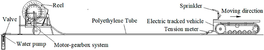
FIGURE 1. Composition of new hard hose traveler and test method.
Energy consumption of a new hard hose traveler mainly consists of driving energy consumption, sprinkler irrigation energy consumption, and tube pressure loss. The driving energy consumption is mainly the energy consumption of the electric tracked vehicle and the operating energy consumption of the reel as well as the tube. The power configuration of the electric tracked vehicle is affected by the operation energy consumption of the reel and the tube. Based on the JP50-180 model of a traditional hard hose traveler, the operation process of the reel and the tube can be divided into two dynamic processes: reel rotation and tube sliding. The tube is unrolled during reel rotation, and the reel load is reduced. During the sliding process of the tube, the unfolded length increases. The pulling tension and energy consumption required for the reel and tube operation are the total tension and total energy consumption. When reel rotation or tube sliding is studied, the superimposed energy consumption from the start to the end of the operation is denoted as cumulative energy consumption of the reel rotation or the tube sliding. The aforementioned is shown in Eqs 4, 5.
In this paper, the unfolded tube length is employed to represent parameter x, which is related to the reel load change and modified quality of the tube sliding. The friction coefficient between the tube and the soil is designated as μ2, which mainly covers the soil surface flatness and soil moisture content. Some influencing factors and parameters are shown in Table 1. The tube is filled with water, and the mobile velocity of the sprinkler, i.e., the velocity of the electric tracked vehicle has no effect on the operation energy consumption of the reel and the tube at a constant velocity, which is used as a reference in this paper. In this paper, the soil moisture content is referred to as the volumetric moisture content of the soil and is measured by the Time Domain Reflectometry method, which is shown in Figure 2. Here, 20.8% was the value before the new hard hose traveler operation in the experiment. The remaining values were the measured during sprinkler irrigation. The ground slope represents the sprinkler angle as it moves upwards. During theoretical analysis, the soil moisture content remains unchanged. During experimental analysis, the ground slope remains unchanged.
where W1 and W2 are the accumulated energy consumption for reel rotation and tube sliding, respectively, J; μ1 is the constant friction coefficient between the machines during rotation; θ is the slope of the ground, °.
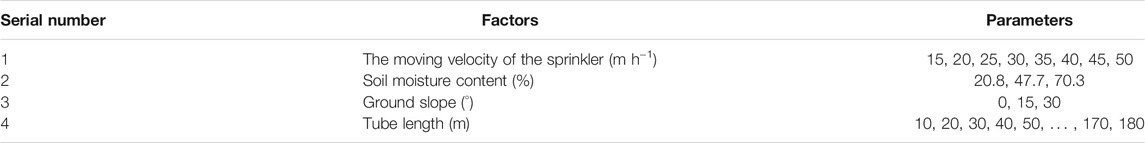
TABLE 1. Factors and parameters.
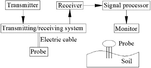
FIGURE 2. The operating principle and Time-domain reflectometry method.
In this paper, the pulling tension and energy consumption are analyzed through the calculation model. Changes in the operating state of the new hard hose traveler are discussed. These changes provide a basis for power configuration design. Based on the above-provided information, four hypotheses are proposed: 1) During unwinding of the reel wound tube, the reel is regarded as a cylindrical rigid body. 2) When reel wound tube layers are changed, the fluctuation process of the required pulling force is neglected. 3) Under a specific working condition, it is assumed that the friction coefficient between the reel and the tube is constant. 4) The suspended length between the part of the tube close to the ground and the winding part on the reel is assumed as negligible.
The winding method of the tube is shown in Figure 3. This method is designated as 1 - n layers from the inside to the outside (the number of tube layers is represented by n, which is a positive integer). In this paper, the distance from the reel center line to the circle point of the tube section is defined as the winding radius. Tube circles are superimposed and three adjacent centers of tube circle are connected to form equilateral triangles, as shown in Figure 3. By combining the unloaded radius of the reel and the diameter of the tube, the winding radius of the nth tube layer can be obtained according to Eq. 6. This method is suitable for any type of traditional hard hose traveler. The calculation method of the reel rotation angle is shown in Eq. 7. The total length of the tube is represented by S, and the length of the tube wound on the reel is designated as (S-x). When the length of the reel tube wound is reduced, the pulling force required for the reel to rotate at a constant speed is significantly lowered, as shown in Eq. 8. Kinetic and cumulative energy consumptions of the reel at a constant speed are shown in Eqs 9, 10.
where Rn is the winding radius of the nth tube layer, m; R0 is the unloaded reel radius, m; d is the tube diameter, m; αn is the rotation angle of the nth tube layer of when the reel is unrolled, rad; i is the total number of PE layers; jn+1 is the total number of tube wounds at the (n+1)-th layer of the reel; Ln is the winding perimeter of each tube in the nth layer, m; F1 is the pulling force required for the reel to rotate at a constant speed, N; m0 is the unloaded weight of the reel, kg; ΔmPE is the weight of a tube full of water per unit length, kg m−1; Tn is the kinetic energy of the reel required to rotate at a constant speed, N m−1.
FIGURE 3. The stacking method of the reel winding tube.
The pulling force required for the tube to slide at a constant ground velocity is gradually increased, as shown in Eq. 11. The cumulative energy consumption of the tube required to slide at a constant speed is shown by Eq. 12:
where F2 is the required pulling force for the tube to slide at a constant ground velocity, N.
Total dynamic pulling force F and operation total energy consumption W of the reel and the tube are shown by Eqs 13, 14, respectively:
The model JP50-180 of the traditional hard hose traveler is chosen in this paper. The inner diameter, outer diameter, and tube length are 40 mm, 50 mm, and 180 m, respectively, while the weight of the reel is 102 kg. The weight of 1 m of the waterless tube is measured by the weighing method. Combined with the amount of water that can be contained in the tube, the full water weight of the tube is approximately 2.592 kg/m. Since most of the soil has a certain viscosity and cannot be completely dried, it is assumed that the soil moisture content under natural drying conditions is 20.7%. The minimum friction coefficient between the tube and the soil is 0.3 (GB/T 21400.1-2008, 2008). Therefore, in this paper, the friction coefficient for a certain soil surface flatness and soil moisture content of 20.7% is also 0.3. After removing the water turbine and turbine gearbox of a traditional hard hose traveler, the friction coefficient of the reel rotation is taken according to the general friction coefficient of metal lubrication, i.e., 0.05. By measuring the circumference of the unloaded reel, the radius is calculated as 0.454 m. After employing Eq. 6, the remaining reel and tube parameters are shown in Table 2. The difference between the calculated and the measured value of the total winding length of each tube layer is not more than 0.4 m, and the deviation rate is approximately equal to 0.5%. Therefore, the calculation method according to Eq. 6 is more accurate. Hence, more effective support for the calculation of the cumulative energy consumption of the reel can be provided.
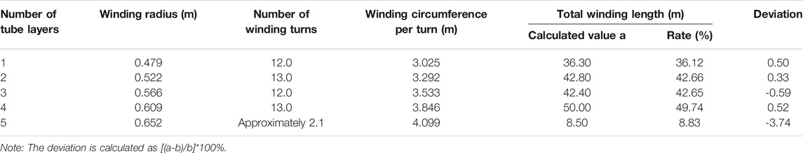
TABLE 2. Reel and tube parameters.
During the operation process of the reel from the full load tube to the no-load tube, according to Eq. 8, the function of the pulling force required for the reel to rotate at a constant speed is shown in Eq. 15, and its maximum value is 278.6 N. The change process of kinetic energy calculation value of the reel rotation is shown in Figure 4. As the tube length on the reel gradually decreases, the kinetic energy demonstrates a stepped downward trend. This step is caused by the tube switching the number of winding layers. Gradual step decrease is mainly caused by the reduction of the wound tube quality. Calculation of the cumulative energy consumption of reel rotation is shown in Figure 5. The maximum value is obtained as 15120.83 J. According to Eq. 10, the curve is divided into five sections, and each segment is represented by a quadratic function. Therefore, the curve is fitted into a quadratic function according to Eq. 16 with a fitting coefficient of 0.998. As the expansion length of the tube increases, the amount of cumulative energy consumption change is gradually reduced reduce. The change parameters of kinetic energy and accumulated energy consumption of the reel are shown in Table 3.
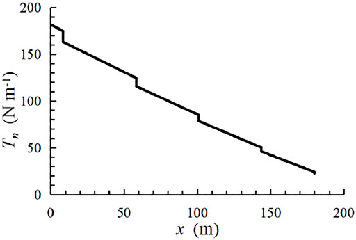
FIGURE 4. The kinetic energy of reel rotation.
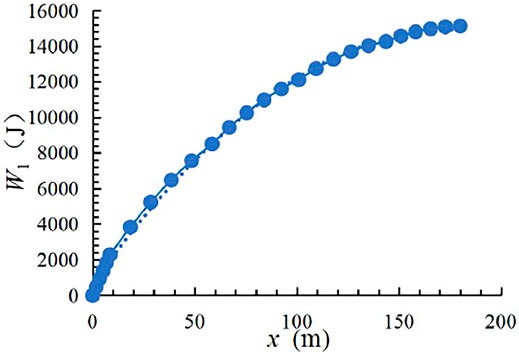
FIGURE 5. Accumulated energy consumption of reel rotation.
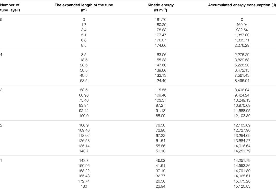
TABLE 3. Change parameters of reel energy consumption.
During the tube pulling process, according to Eqs 11, 12, when θ is not substituted into a specific value, the functions of the required pulling force and cumulative energy consumption of the tube are shown in Eqs 17, 18, respectively. As previously demonstrated, with a continuous increase of the ground slope from 0°, 15°, and 30°, the required tensile force, and energy consumption of the tube are also increased. When the ground slope is 0°, maximum values of the tensile force and maximum cumulative energy consumption are 1372.86 N and 123 456.96 J, respectively. The change process of cumulative energy consumption for tube sliding is shown in Figure 6.
FIGURE 6. Cumulative energy consumption of tube sliding.
According to Eqs 17, 18, the dynamic function of the total tensile force and total reel and tube energy consumption can be determined. With an increase in the length of the pulled-out tube, the required pulling force and accumulated energy consumption for reel rotation are gradually reduced. Cumulative energy consumption of reel rotation and tube sliding accounts for 10.91 and 89.09% of the total energy consumption, respectively. Moreover, tube sliding accounts for the highest proportion.
During the test, calculating energy consumption via pulling force is the same as the calculation model. Therefore, the test research will only focus on the pulling force. First, the pulling force of the tube sliding is investigated. Second, the total pulling force of the reel and tube operation is analyzed. By observing the difference between the two, the pulling force of the reel rotation during the test is obtained. The test assumes fixed soil surface flatness, and the effect of soil moisture content and tube length on tube sliding will be considered.
In this paper, the tube is pulled out by a small machine and moved along a straight line. A measuring bucket, which is used to calibrate the position of the tension meter and measure the pulling force, is placed every 10 m from the reeling car. The test operation process of the reel and the tube is shown in Figure 7. The test site is in Zibo City, Shandong Province, China. The terrain is relatively flat, and the ground slope is within ±1°. Therefore, the default value is set as 0°. The pulling force of the tube is measured by a tension meter (a range of 0.1–10 kN), and the data is acquired at multiple velocities and the average value is taken. The schematic diagram of the test method is shown in Figure 1. After the tube is filled with water, the valve is closed and the pump is cut out. Lastly, the tension meter is connected between the small machine and the tube.
FIGURE 7. The test process of dragging the tube with water.
During the test, due to the local unevenness of the field roads, the soil of the field roads is leveled to improve the accuracy of the measured pulling tension between the tube and the soil. The aforementioned provides a reference for power configuration design and future research. The soil surface flatness is measured by the chain measurement method (Zhang et al., 2016), which is shown in Figure 8. The calculation method of soil surface flatness is shown in Eq. 19. Within the leveling method, the bumps are drawn, filled with soil, and compacted by the movement of small machine, repeatedly. The leveled soil surface is shown in Figure 9. The soil surface flatness after treatment was 99.6%.
where C is soil surface flatness, %; H1 is the length of chain, m; H2 is the length of a tape measure when the chain is relatively close to the measured soil, m.
FIGURE 8. Measurement method of soil surface flatness.
FIGURE 9. The leveled soil surface.
The test was carried out on a road with three soil moisture contents. An 18 m closed tube with water is pulled by a motor at a constant speed. The weight of an 18 m tube with water per unit length is 443.6 N. A tension meter with a range of 0–500 N and an accuracy of 0.1 N pulls the tube at a constant speed, and the average value of multiple measurements is taken. The friction data of different soil moisture contents are shown in Table 4, while the friction coefficient between the tube and the ground is shown in Eq. 20.
Where F′ is the average value of friction for 18 m tube, N; m´ is the quality of 18 m tube with water, kg.
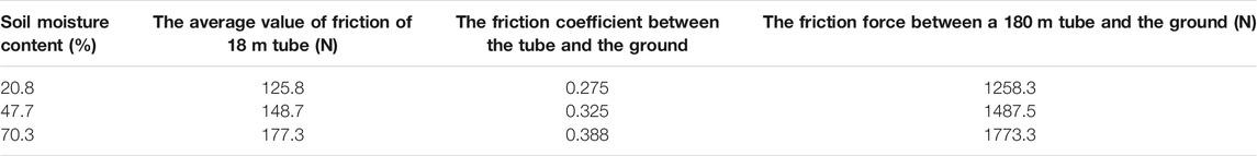
TABLE 4. Friction data of different soil moisture contents.
According to Table 4, with an increase in the soil moisture content, the friction coefficient between the tube and the soil increases. The coefficient value is approximately in the range of 0.275–0.388. After proportional conversion, the minimum and maximum friction force between the 180 m tube and the soil is 1258.3 N and 1773.3 N, respectively. Therefore, the required pulling force and energy consumption for tube sliding increase with an increase in the soil moisture content.
During reel and tube operation, the linear relationship between the unfolded tube length and the average value of the total pulling force is shown in Figure 10. The fitting equation and fitting coefficient R2 of each soil moisture contents are shown in Eq. 21 and Table 5, respectively. It can be observed that the combined effect is the most optimal. With an increase in the soil moisture content, the total pulling force and the slope of the fitted curve are both increased. As the length of the expanded tube increases, the total pulling force increases linearly. As the soil moisture content becomes higher and the length of the tube increases, the superposition of dual factors causes the cumulative amount of the total pulling force to continuously increase. Therefore, the slope of the fitting curve gradually increases. The maximum pulling forces of three types of soil moisture contents are 1280.73, 1532.49, and 1828.24 N, respectively.
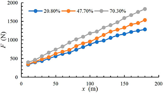
FIGURE 10. The total pulling force of the reel and the tube.
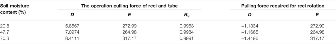
TABLE 5. Coefficient of the fitting equation for the reel and the tube.
where U(x) is the universal pulling force which represents the operation pulling force of the reel and the tube or the pulling force required for the reel rotation, N; Parameters D and E are the equation coefficients.
According to the conducted pulling force analysis, when the reel is fully loaded with the tube, the maximum pulling force of the reel rotating at a constant speed is 317.17, 264.98, and 272.99 N, respectively, and the average value is 285.02 N. The equation coefficients are also shown in Table 5.
Since the weight of the reel in a fully loaded tube is 548.58 kg, the theoretical and tested values of the maximum reel rotation pulling force are 278.6 and 285.02 N, respectively. The deviation rate of the pulling force is 2.3%. The deviation rate equation is shown in Eq. 22.
where p1 is the deviation rate of the reel rotation pulling force, %; F1’ is the tested value of the reel rotation pulling force, N.
When the soil moisture content and flatness are 20.7 and 99.6%, respectively, and the tube is dragged, the pulling force and the friction coefficient are 1258.3 N and 0.275, respectively. These values deviate from theoretical ones by 8.3%. The calculation equation is shown in Eq. 23. The friction coefficients of other soil moisture content are 0.325 and 0.388, respectively. These values belong to the category of the national standard regarding friction coefficient reference range of 0.3–1.0. Therefore, the measured friction coefficient between the tube and the soil in the test is more reliable.
where p2 is the deviation rate of the tube sliding pulling force, %; F2′ is the tested value of the tube sliding pulling force, N.
The operating costs of the one-time unrolled tube are one of the key parameters of the traditional or new hard hose travelers. During the unwinding of the tube, the reel rotates. By combining the parameters of the moving velocity of the sprinkler and the tube length, the one-time unrolled tube time is shown in Table 6. Since the energy consumption of expanding the tube is not affected by the moving velocity of the sprinkler, the longer it takes to expand the tube, the higher are the operating costs. When the new hard hose traveler is designed, under the condition that the same precipitation depth is met, shortening of the one-time unrolled tube time is beneficial to reducing expenses. Chinese electric power transmission and distribution for well-facilitated farmland construction is taken as an example. Under certain conditions, when the maximum cumulative energy consumption of the unrolled tube is 123456.96 J, its operating cost is 0.0185 CNY, as shown in Table 7.

TABLE 6. The one-time unrolled tube time.
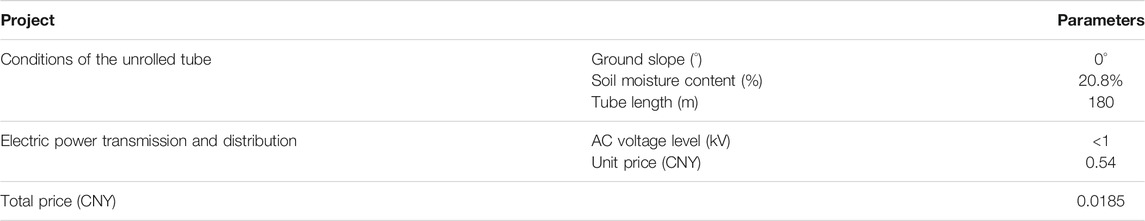
TABLE 7. The operating costs of the one-time unrolled tube.
According to the presented data, the energy consumption of the new hard hose traveler can be reduced by increasing the moving velocity of the sprinkler (i.e., the moving velocity of the tube) and reducing the driving mechanism energy consumption of the sprinkler radial movement. Thus, the operating costs will be reduced.
The power configuration of an electric tracked vehicle is the power source for the reel and tube operation of a new hard hose traveler. Since the maximum friction coefficient between the tube and the soil is 1.0 (GB/T 21400.1-2008, 2008), the electric tracked vehicle needs to overcome a frictional force between the reel and the tube of approximately 4851 N (Eq. 13). Performance design parameters of the electric tracked vehicle are shown in Table 8. Considering the operation start and some accidental factors, the external pulling force that has to be overcome is set to 6500 N. To achieve remote control of new hard hose traveler and more flexible anti-friction ability, the rubber crawler chassis is driven by the battery power supply and an AC380V servo motor. Power configuration plays a decisive role in overcoming the resistance of the electric tracked vehicle, as well as operation resistance between the reel and the tube. Resistance of the electric tracked vehicle is divided into operation resistance and internal rolling friction resistance. The sprinkler gear and the transfer gear are set for the sprinkler irrigation operation and the transformation of the new hard hose traveler.
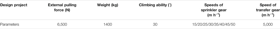
TABLE 8. Performance parameter design of electric tracked vehicle.
Driving resistance includes rolling friction of the crawler and the soil, adhesion, and slant downward static friction. All of them are caused by driving straight, turning, side-slip, and climbing the slope upward of the crawler. The coefficients of rolling friction and adhesion of electric tracked vehicles in normal operation on the soil are 0.07 and 1.0, respectively (Chen and Gu, 1965). The internal rolling friction resistance mainly includes the meshing friction between the driving wheel and the crawler and the rolling friction between the guide wheel and the crawler. The friction coefficient is generally between 0.05 and 0.07 (Chen and Gu, 1965). Therefore, the mean value of 0.06 is taken in this paper.
The AC380V servo motor has three times the overload capacity than the rated power and some overload time. During sprinkler irrigation operation and transfer, possible extreme operating states of new hard hose traveler electric tracked vehicles are divided into a long and short time. The friction coefficient of various operating states is defined as μ3 (including the rolling friction between the crawler and the soil, and the internal rolling friction of the electric tracked vehicle). The power of these states is converted by Eq. 24 and shown in Table 9.
where P0 is the limit power, W; F3 is the force that needs to be overcome in various extreme states of the electric tracked vehicle, N; v is the traveling speed of the electric tracked vehicle, m h−1; η1 is the efficiency of the transmission device of the electric tracked vehicle which is generally in the range of 0.95–0.98, i.e., it is taken as η1 = 0.95 in this paper; M is the weight of the electric tracked vehicle, kg.
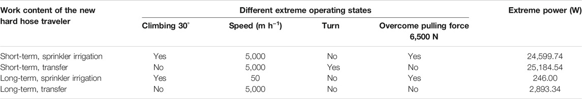
TABLE 9. The extreme power of the new hard hose traveler in different operating states.
If the motor power reserve coefficient is selected as 1.2, the maximum short-term and long-term limit power required of the electric tracked vehicle is 30221.45 and 3476.80 W, respectively. Since the electric tracked vehicle achieves normal movement and steering via forward and reverse rotation of the two motors and different speeds and reduces costs, when choosing two AC380V servo motors with a power of 5500 W, all working requirements of the electric tracked vehicle can be met.
In this paper, a new hard hose traveler with the function of electric drive and self-propelled was developed to reduce the energy consumption of traditional hard hose travelers and achieve intelligent operation. The operational energy consumption of reel and polyethylene tubes is an important part of the energy consumption of the proposed hard hose traveler. Therefore, the traditional JP50-180 reel sprinkler was selected. The required pulling force and operation energy consumption of the reel and the tube were theoretically and experimentally analyzed. A reasonable power configuration of the new hard hose traveler was designed. The following conclusions are drawn:
A calculation model for the dynamic change of the pulling force and energy consumption of reel and tube operation was constructed. The difference between the calculated and the measured values of the total winding length of each tube layer was not more than 0.4 m, with the deviation rate being approximately equal to 0.5%. The reel was fully loaded to no-load tubes. The maximum value of the pulling force and cumulative energy consumption of reel rotation were 278.6 N and 15 120.83 J, respectively. When the ground slope was 0° and the friction coefficient between the tube and the soil was 0.3, the maximum value of the pulling force and cumulative energy consumption of the tube sliding were 1372.86 N and 123 456.96 J, respectively. These values account for 10.91 and 89.09% of the total energy consumption, respectively. As the length of the tube increased, the kinetic energy of reel rotation showed a stepwise downward trend. Moreover, the pulling force and cumulative energy consumption showed an upward trend in the form of a quadratic function. With an increase in the ground slope, the required pulling force and energy consumption of the tube were also increased.
For three soil moisture contents of 20.8, 47.7, and 70.3%, the friction coefficient of the drag tube was 0.275, 0.325, and 0.388, respectively, and the maximum pulling force were 1258.3, 1487.5, and 1773.3 N, respectively. The required pulling force and energy consumption for tube sliding increased with an increase in the soil moisture content. The maximum test value of the reel rotation was 285.05 N, and the deviation rate from the theoretical value was 2.3%. When the soil surface had the same flatness and the soil moisture content was 20.8%, the theoretical and experimental value of the pulling force had a deviation rate of 8.3%. The operating costs of the one-time unrolled tube are approximately 0.0185 CNY.
The conducted study shows that the required pulling force of the reel and the tube under the working conditions of the new hard hose traveler was 6500 N. The power configuration of the electric tracked vehicle is the power source for the operation of the hard hose traveler reel and the tube. The design plan and power configuration were provided according to the working mode of the electric tracked vehicle. The power of two AC380V servo motors was 5500 W each.
The other energy consumption of the new hard hose traveler and other parts design on electric tracked vehicle will be studied in future works.
The original contributions presented in the study are included in the article/supplementary material, further inquiries can be directed to the corresponding author.
ZX conceived and designed the study and completed the paper in English. HL and QX revised it critically for important intellectual content and gave good research advice and revised the manuscript. All authors have read and agreed to the published version of the manuscript.
This research was supported by the following grants: the National Natural Science Foundation of China (51939005, 51809119), Postgraduate Research & Practice Innovation Program of Jiangsu Province (KYCX19_1602).
The authors declare that the research was conducted in the absence of any commercial or financial relationships that could be construed as a potential conflict of interest.
All claims expressed in this article are solely those of the authors and do not necessarily represent those of their affiliated organizations, or those of the publisher, the editors and the reviewers. Any product that may be evaluated in this article, or claim that may be made by its manufacturer, is not guaranteed or endorsed by the publisher.
Biolan, I., Sovaiala, G., and Visan, A. L. (2012). Optimization of the Hydraulic Bellows Engine Parameters Used to Drive Irrigation Reel Hose Machine - IATF 300. Adv. Mater. Res. 463-464, 1137–1140. doi:10.4028/www.scientific.net/amr.463-464.1137
Burt, C. M., Clemmens, A. J., Bliesner, R., Hardy, L., and Merriam, J. L. (1999). Selection of Irrigation Methods for agriculture[M]. San Luis Obispo: American Society of Civil Engineers.
Cui, Z., Guan, C., and Chen, Y. (2019). Design of Small Multi-Functional Electric Crawler Platform for Greenhouse. Trans. Chin. Soc. Agric. Eng. (Transactions CSAE) 35 (9), 4857 (in Chinese with English abstract). doi:10.11975/j.issn.1002-6819.2019.09.006
Fan, S. (2017). Lightweight Design and Dynamics Research of Chassis Frame for Orchard Electric Tracked Vehicle [D]. Guangzhou: South China Agricultural University.
GB/T 21400.1-2008 (2008). Traveller Irrigation Machines-Part1:Operational Characteristics and Laboratory and Field Test methods[S]. Beijing: Standards Press of China.
Ge, M. (2018). Study on Irrigation Quality and Optimal Design of Solar Driven Hard Hose Traveler[D]. Yang ling, China.: Yang ling: Northwest A&F University.
Ge, M., Wu, P., Zhu, D., Zhang, L., and Cai, Y. (2020). Optimized Configuration of a Hose Reel Traveling Irrigator. Agric. Water Manage. 240, 106302. doi:10.1016/j.agwat.2020.106302
Li, D., Zhu, D., Ge, M., Wu, S., Wang, R., Wang, B., et al. (2019). Optimal Configuration and Field Experiments for the Photovoltaic System of a Solar-Powered Hose-Drawn Traveler. Trans. ASABE (American Soc. Agric. Biol. Engineers) 62 (6), 1789–1801. doi:10.13031/trans.13298
Li, H. (2018). Design and Research of Tracked Electric Bamboo and Wood Pruning Tip Cutting and Transportation Machine[D]. Hangzhou: Zhejiang Agriculture & Forestry University.
Oakes, P. L., and Rochester, E. W. (1980). Energy Utilization of Hose Towed Traveler Irrigators. Trans. ASAE 23 (5), 1131–1134. doi:10.13031/2013.34733
Pan, J. (2019). Design and Study of Large Scale Hydraulic Drive Reel Sprinkler Irrigation Machine and its Control System[D]. Xuzhou, China.: China University of Mining and Technology.
Rochester, E. W., Flood, C. A., and Hackwell, S. G. (1990). Pressure Losses from Hose Coiling on Hard-Hose Travelers[J]. Trans. ASAE 33 (3), 834–0838. doi:10.13031/2013.31408
Rochester, E. W., and Hackwell, S. G. (1991). Power and Energy Requirements of Small Hard-Hose Travelers. Appl. Eng. Agric. 7 (5), 551–556. doi:10.13031/2013.26267
Tang, L., Yuan, S., Malin, M., and Parameswaran, S. (2017). Secondary Vortex-Based Analysis of Flow Characteristics and Pressure Drop in Helically Coiled Pipe. Adv. Mech. Eng. 9 (4), 1. doi:10.1177/1687814017700059
Tang, L., Yuan, S., and Tang, Y. (2018). Analysis on Research Progress and Development Trend of Hose Reel Hard Hose Traveler [J]. Trans. Chin. Soc. Agric. Machinery 49 (10), 1–15. doi:10.6041/j.issn.1000-1298.2018.10.001
Tang, L., Yuan, S., and Tang, Y. (2014). Flow Resistance Study of Helically Coiled Pipe for A Hose Reel Hard Hose Traveler Based on CFD Analysis [J]. ASABE.
Tang, Y., Zhu, X., and Mei, X. (2014). Performance Test of Water Turbine of JP50 Reel Sprinkler[J]. China Rural Water and Hydropower 2014 (02), 26–29.
Xu, G., Song, Y., and Qiu, X. (2022). Matching Design and Test of Power System for Electric Self-Propelled Crawler Chassis of Orchard[J]. J. Agric. Mechanization Res. 44 (04), 251–255. doi:10.13427/j.cnki.njyi.2022.04.045
Yang, L., Tang, Y., and Tang, L. (2018). Brushless DC Motor Drive Characteristics and System for Reel-Type Hard Hose Traveler. J. Drainage Irrigation Machinery Eng. 36 (08), 690–695. doi:10.3969/j.issn.1674-8530.18.1159
Yuan, S., Niu, G., Tang, Y., Lingdi, T., and Xiangyuan, Z. (2014). Experiment and Numerical Estimation of Performance of Hydraulic Turbine of JP50 Reel Sprinkle. J. Drainage Irrigation Machinery Engineering(JDIME) 32 (7), 553557+562. (in Chinese). doi:10.3969/j.issn.1674-8530.13.0187
Zhang, C., Tang, Y., and Tang, L. (2015). Efficiency Analysis and Experimental of the Type JP75 Hose Reel Hard Hose Traveler[J]. J. Agric. Mechanization Res. 37 (09), 37–40.
Zhang, H. (2016). Design of Multifunctional Orchard Lifting Platform in Electric Crawler Type [D]. Guangzhou: South China Agricultural University.
Zhang, M., and Wang, H. (2005). Experimental Study of the Pressure Loss of Hoses of Hard Hose Traveler[J]. Chin. Agric. Mechanization 2005 (03), 58–59. doi:10.3969/j.issn.1006-7205.2005.03.019
Keywords: hard hose traveler, reel rotation, polyethylene tube sliding, energy consumption, soil moisture content, power configuration
Citation: Xu Z, Li H, Jiang Y, Xiang Q and Tang P (2022) Operation Energy Consumption Study on Reel and Polyethylene Tube of a New Hard Hose Traveler. Front. Energy Res. 9:817262. doi: 10.3389/fenrg.2021.817262
Received: 17 November 2021; Accepted: 27 December 2021;
Published: 13 January 2022.
Edited by:
Xiaojun Li, Zhejiang Sci-Tech University, ChinaReviewed by:
Jinjing Sun, University of Shanghai for Science and Technology, ChinaCopyright © 2022 Xu, Li, Jiang, Xiang and Tang. This is an open-access article distributed under the terms of the Creative Commons Attribution License (CC BY). The use, distribution or reproduction in other forums is permitted, provided the original author(s) and the copyright owner(s) are credited and that the original publication in this journal is cited, in accordance with accepted academic practice. No use, distribution or reproduction is permitted which does not comply with these terms.
*Correspondence: Hong Li, aGxpQHVqcy5lZHUuY24=
Disclaimer: All claims expressed in this article are solely those of the authors and do not necessarily represent those of their affiliated organizations, or those of the publisher, the editors and the reviewers. Any product that may be evaluated in this article or claim that may be made by its manufacturer is not guaranteed or endorsed by the publisher.
Research integrity at Frontiers
Learn more about the work of our research integrity team to safeguard the quality of each article we publish.