- College of Electrical Engineering and New Energy, China Three Gorges University, Yichang, China
In view of the difficulty of applying the refine modeling of combined heat and power (CHP) units to the optimization scenario of integrated energy system, a CHP unit model based on working point linearization modeling is proposed, and its variable load characteristics are analyzed. Firstly, the dynamic coupling relationship of CHP unit is analyzed, and the nonlinear dynamic model of the unit is constructed. Then, under the pure condensation and heating conditions, the linearized Laplace transform model of the working point is established, and the variable load capacity under the independent action of control variables is analyzed to test the availability of the Laplace model. On this basis, the dynamic adaptive particle swarm optimization algorithm is used for multivariable cooperative control to test the open-loop characteristics of the variable load capacity of the unit. At the same time, the control strategy of electrothermal cooperation and safety self-test is designed to adjust the control variables, and test the closed-loop characteristics of the unit’s regulation ability. Finally, a 300-MW steam extraction CHP unit is taken as an example to verify the applicability of the unit model and the effectiveness of the control strategy.
Introduction
Clean, low-carbon, and efficient energy use plays an important role in realizing the strategic goal of “double carbon.” Combined heat and power (CHP) plant is becoming the main energy supply source of the electrothermal integrated energy system (IES) with its superior comprehensive energy supply efficiency (Sun et al., 2021). The modeling of the CHP unit variable load capacity is very important for the optimal calculation of power dispatching, frequency regulation, and other scenarios of the IES (Ye et al., 2012; Zhang et al., 2021). However, its refined modeling mechanism is complicated, and the fast dynamic regulation characteristics after optimization control transformation are complex (Shen et al., 2017; Shen et al., 2020a), which makes it difficult to accurately describe the variable load capacity of the unit. Therefore, the research on the description method of the dynamic regulation characteristics of the CHP unit during the variable load process is of great significance to support the application of the CHP unit in the scenario of the IES.
The dynamic characteristics of the CHP unit are not only affected by its internal physical structure attributes but also related to the operation mode, the working condition, the external environment, and other factors (Wang, 2013). At present, it is difficult to obtain an accurate description of the dynamic characteristics of the unit. A mathematical model that meets certain accuracy requirements and reflects the main dynamic characteristics of the unit is often established by reasonable simplification and approximation, combined with mechanism analysis and experimental modeling (Yang et al., 2018; Yang et al., 2019; Zhu et al., 2020; Li et al., 2021). Algebraic equations are usually used to describe the feasible region, climbing, and standby capacity of the CHP unit model (Liu et al., 2021). This model is mostly used in the calculation scenario of the unit participating in system long-time scale optimal dispatching (Zhang et al., 2018). The algebraic equation linearization model often ignores the continuous time variation characteristics of the unit output, and there is the assumption that the unit output power can change instantaneously. The model undoubtedly expands the rapid load changing capacity of the unit, which is easy to cause the possibility that the dispatching plan cannot be accurately realized, that is, there is the problem of energy nondeliverability (Gao and Yan, 2017). The mathematical description considering the internal characteristics of the unit is in the form of differential algebraic equations, which adopts the optimal control method to improve the short-term rapid regulation ability of the unit and participates in the system frequency modulation calculation scene (Wang et al., 2018; Yang et al., 2021). The constraints of differential algebraic equations will make the optimization problem a highly nonlinear dynamic optimization problem. This kind of an optimization problem is difficult to solve directly. Approximating differential variables through a discrete method will lead to the solution of large-scale optimization problems being easy to fall into a dimensional disaster (Wang, 2012), long solution time, and poor accuracy (Shen et al., 2021a; Shen and Raksincharoensak, 2021a), and cannot be solved online and in real time (Shen et al., 2020b; Shen et al., 2021b; Shen and Raksincharoensak, 2021b). The modeling of the dynamic characteristics of the unit variable load process faces the challenge of meeting the calculation accuracy and solution speed while taking into account the accurate description of unit dynamic characteristics.
Laplace-transform a real variable function and perform various operations in the complex number field, and then perform the inverse Laplace transform to obtain the corresponding results in the real number field, which is often much easier to calculate than directly obtaining the same results in the real number field (Beerends et al., 2003). Yang et al. (2020) proposed a generalized circuit modeling method based on Laplace transform, which transforms the complex transmission characteristics of multi-energy networks in the time domain into a simple algebraic problem in the Laplace domain. Laplace transform is particularly effective for simplifying differential equations, which can be transformed into easily solved algebraic equations (Hooman and Randolph, 2020), so as to simplify the calculation. The analysis and synthesis of the control system are based on Laplace transform. Gao and Tian (2020) linearized the nonlinear dynamic model of the heating unit with small deviation, obtained the transfer function matrix model, analyzed the coupling relationship of the unit, and studied the thermal power load decoupling control method of the unit. Liu et al. (2005) linearized the nonlinear model at different load/pressure operating points and studied the load pressure nonlinear characteristics of the 660-MW unit. After linearizing the small deviation of the dynamic model of the heating unit (Deng et al., 2017), the transfer function matrix model including the characteristics of the heating side is obtained, the thermoelectric coupling characteristics are analyzed, and the decoupler is designed. By introducing Laplace transform into linearization at different working points and using a transfer function instead of a differential equation to describe the characteristics of the system, the whole characteristics of the control system can be determined intuitively and simply, the motion process of the control system can be analyzed, and the adjustment strategy of the control system can be provided. For the linearization of the CHP unit at the working point, it is rare to use Laplace transform modeling to make the model suitable for the flexible demand of the variable load capacity of the IES.
To solve the above problems, firstly, a simplified nonlinear dynamic model of the CHP unit is constructed. Then, the linearized Laplace transform model of the working point under pure condensation and heating conditions is established to analyze the variable load capacity of the unit when each control variable acts alone and cooperatively. Furthermore, the control strategy of electrothermal cooperation safety self-test is used to test the dynamic regulation ability of the unit in the variable load process. Finally, taking the 300-MW steam extraction CHP unit as an example, the dynamic characteristics of the variable load process of multivariable collaborative control are tested to verify the effectiveness of open-loop and closed-loop control strategies.
Combined Heat and Power Unit Model
Dynamic Relationship of Combined Heat and Power Unit
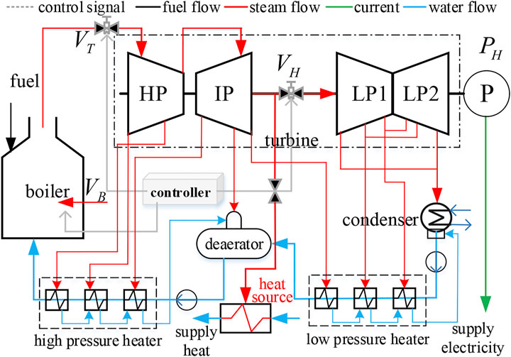
As shown in Figure 1, the fuel volume
During the operation of the extraction type CHP unit, the electric power and thermal power are comprehensively determined by the fuel flow, main steam pressure, extraction steam flow, temperature, and other variables controlled by its valve. The load-pressure simplified nonlinear dynamic model of the pure condensing unit (Liu et al., 2014) is combined with the model in the study by Tian (2005), and the differential equation mathematical model of the dynamic coupling relationship between the electric power, thermal power, and control valve of the CHP unit is obtained. The simplified nonlinear dynamic model of the CHP unit is given by:
where
Linearization Model of Operating Point of Combined Heat and Power Unit
The nonlinear model is linearized at a certain working point, and the linearized model can accurately reflect the dynamic and static characteristics of each link of the system near the working point. The model described in Eq. 1 is linearized to measure the action relationship between various inputs and outputs in the model and the influence of system nonlinearity on the controlled object. Firstly, write Eq. 1 in incremental form. The linear model near the equilibrium point is obtained by small deviation linearization:
Secondly, the Laplace transform of the incremental equation is obtained. Assuming that the initial condition is zero, the Laplace transform is taken for the linear differential Eq. 2 of the system, and the incremental symbol is omitted, the following can be obtained:
Then, the linear model is appropriately simplified and equivalent to obtain a set of linear equations describing the dynamic characteristics of the unit transfer process, and the system thermoelectric coupling relationship model after linearization of the working point can be obtained, which is expressed in the form of the transfer function matrix as follows:
The elements of the thermoelectric coupling relationship matrix are
where
Under different input operating points, the transfer function of the CHP unit will be different. This nonlinearity only changes the model parameters, and the model structure is unchanged. The Laplace transform model with a linearized working point takes into account the advantages of simplicity, being in real time, and high precision. In this paper, the variable load characteristics of the CHP unit under pure condensation and heating conditions will be studied.
Analysis Method of Variable Load Characteristics of Combined Heat and Power Unit
Open-Loop Variable Load Characteristic Test and Multicontrol Variable Synergy Method
Variable Load Characteristic Test With Independent Action of Control Variables
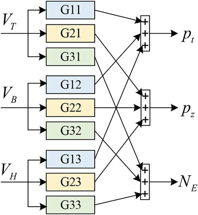
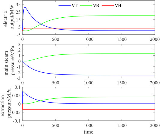
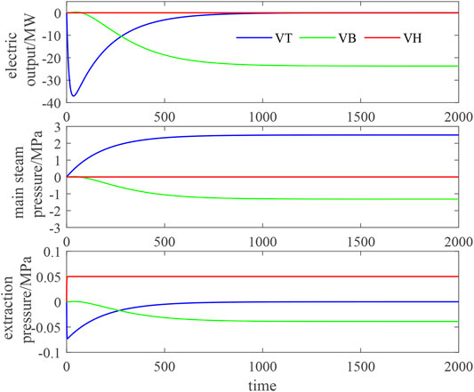
The functional relationship between control variables and output variables is shown in Figure 2. The pure condensation condition and heating condition are modeled in Simulink to test and analyze the input–output relationship between variable load process variables. See Supplementary Appendix SB for the parameters of the working condition model. The dynamic characteristics of the boiler steam turbine heating system and the variable load capacity are obtained by analyzing the output change when the control variables act alone. Under the heating condition, apply step changes of 10 t/h, 10, and 10% on
Figure 3 shows the change of the object output under the step disturbance of boiler fuel
Figure 4 shows the object output changes under the step disturbance of boiler fuel volume
The dynamic characteristics of the linearized model after univariate action are basically consistent with the original model (Wang, 2013). Therefore, it can be considered that the linearized model has good reproducibility. It is feasible to analyze and study the dynamic regulation characteristics of the variable load process according to the linearized model.
The independent action test of control variables under the two working conditions shows that the control variable regulation has different effects on the load change of the CHP unit.
Multicontrol Variable Synergy Method
In this paper, the optimization algorithm is used to determine the three control variables of
where
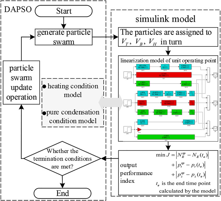
Given the electric power variable load demand, the optimization algorithm flow of the synergy of the three control variables is shown in Figure 5. The connection between DAPSO and the Simulink model is through the particle (i.e., control variables
Thermal System Constraints
CHP unit control shall be able to realize accurate variable load tracking, reliable heat supply, and safe pressure fluctuation. Heating and power generation are affected by boiler fuel volume
Control scheme I:
where
In order to ensure the safe and stable operation of the unit, the influence of output variable fluctuation shall be considered in the regulation process, and the control system path constraint (Tian et al., 2017) shall be met, as shown in Eq. 18a. The steady-state value of each output variable shall not exceed the allowable error range, and the system final value constraint shall also be satisfied (Tian et al., 2015), as shown in Eq. 18b.
where
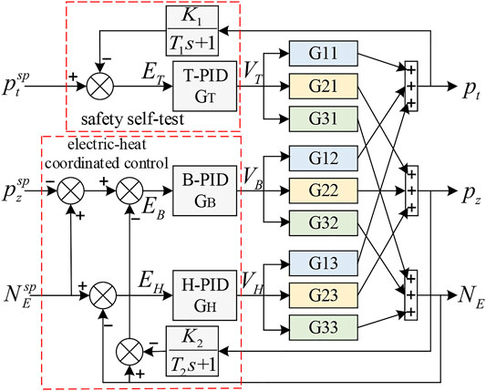
According to the above control process requirements and the optimization control strategy proposed in the study by Wang et al. (2019), the control concepts of disturbance compensation and multivariable coordination are further adopted. Through the design of three key control modules: electrothermal coordination, thermal state reconstruction, and accurate energy balance, and considering the main influencing factors of main steam fluctuation, a new electrothermal power coordinated distribution and pressure safety self-test control strategy is proposed. The parameters of the control system are manually set by an empirical method to realize the three key functions of the CHP unit control system: accurate electric power tracking, rapid thermal power recovery, and safe and stable operation of the system. The structure of the control system is shown in Figure 6.
Control scheme II:
Among them,
The variable load regulation process of the CHP unit will lead to large changes in the heating capacity of the unit in a short time, and the heat transfer is delayed. The increase or decrease in long-term accumulated heat will lead to the change of the ambient temperature of the heat load, thus affecting the comfort of users. Therefore, after the step signal of variable load disturbance is given for the dynamic model of the CHP unit, it is necessary not only to test the changes of main steam pressure and electric power but also to further analyze the change process of extraction steam flow in the optimal control cycle. The influence of heat change caused by extraction steam flow fluctuation on heat load demand is quantitatively analyzed, and calculate it according to the following method (Wang et al., 2019) (Supplementary Table S2):
where
The CHP unit model has obvious system nonlinearity. The object transfer function parameters contain the input variable information that determines the operating point, so the transfer function has different nonlinear characteristics at different operating points. By using the same PID controller setting parameters to test the control quality of the unit system under different working conditions of heating and pure condensation, how strong the nonlinearity of the CHP unit is measured. Through the analysis of simulation results to determine the method that setting controller parameters can ensure the system control quality under common working conditions, guide the coordinated control system structure or controller parameters to make some adjustment, so as to adapt to the changes of controlled object parameters.
Example Analysis
In order to verify the effectiveness of the models and methods proposed in this paper, a 300-MW steam extraction heating unit is used to build a model on a MATLAB/Simulink platform for simulation. The variable load open-loop characteristics of the unit are tested by controlling variable disturbance, and the variable load closed-loop dynamic characteristics of the unit are tested by designing control strategy. The response curves of each output are simulated to verify the reproducibility of the linearized model, and the effectiveness of the control method and strategy is analyzed. Relevant parameters of the unit and operating point parameters under pure condensation and heating conditions are shown in Supplementary Appendix SA, SB.
Open-Loop Characteristic Analysis
Under the heating condition, when the electric load is given a step signal of 25 MW, the regulation index performance of the system and the optimization process of three control variables are shown in Figure 7. After setting 20 populations of parameters and 20 iterations, the optimization algorithm can stably calculate three control variables after 30 simulation calculations, and the performance fitness value of the regulation index of the system can stably converge to less than 0.2. The
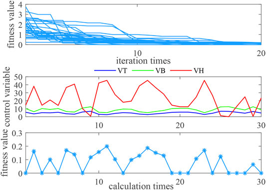
FIGURE 7. Convergence of DAPSO and optimization results of control variables under the heating condition.
When the step signal of -25 MW is given for the electric load under the pure condensation condition, the regulation index performance of the system and the optimization process of three control variables are shown in Figure 8. With the same algorithm parameter setting as the heating condition, the adjustment index performance fitness value of the system can stably converge to less than 0.5. The
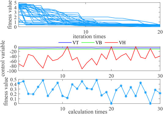
FIGURE 8. Convergence of DAPSO and optimization results of control variables under the pure condensation condition.
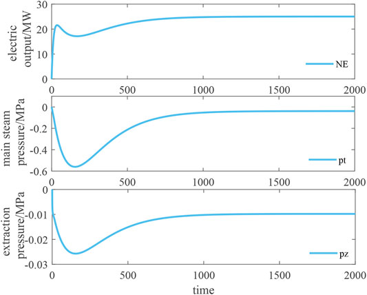
Under the heating condition and the pure condensation condition, the output changes of the system under the synergistic action of control variables are shown in Figures 9, 10. Under the heating condition, given the step signal and adjusting the control variables (5.52%, 10.15 t/h, 14.39%), after about 1,500 s, the output power of the system accurately meets the 25 MW required for the variable load, the main steam pressure is adjusted back to −0.04 MPa, and the extraction pressure is stabilized to −0.01 MPa. Under the pure condensation condition, given the step signal and the regulated control variable (−5.59%, −10.58 t/h, −8.54%), after about 1,500 s, the system output power accurately reaches −25 MW required by the variable load, the main steam pressure is adjusted back to 0.0007 MPa, and the extraction pressure is stabilized to 0.0015 MPa.
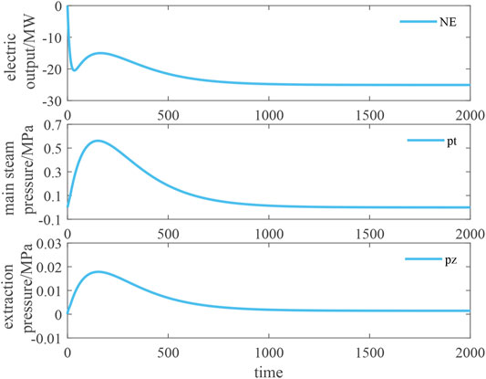
FIGURE 10. Synergistic regulation effect of three control variables under the pure condensation condition.
The open-loop regulation eliminates the complex PID setting work and can accurately complete the electric power regulation. However, there is a difference between the safe main steam pressure involved in the variable load process and the extraction pressure of heating, and the calculation time of one-time optimization is about 5 min, which is a long adjustment time.
Closed-Loop Characteristic Analysis
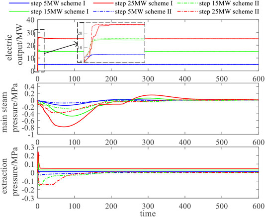
Based on the established s-domain system simulation model of the CHP unit, the step signals of the electric load are given as 5, 15, and 25 MW, respectively. The closed-loop control simulation analysis is carried out by using control scheme I and control scheme II. The changes of electric power, main steam pressure, and extraction pressure of the CHP unit are shown in Figure 11.
Under the two control schemes, the electric power of the unit increases rapidly. In the three variable load scenarios, it takes 10, 35, and 80 s, respectively, to accurately reach the step expected steady-state value. The stronger the variable load, the longer the regulation time. Specifically, the response speed and climbing rate of scheme II are slightly better than scheme I in the first 30 s of regulation.
The dynamic fluctuation of the main steam pressure regulation process is directly related to the safe and stable operation of the unit. It can be seen from the figure that the larger the variable load, the more intense the main steam pressure fluctuation. Scheme II improved by the pressure safety self-test control strategy effectively reduces the pressure fluctuation in the control process. Compared with scheme I, the peak value of pressure fluctuation in scheme II is reduced by about 50%, and all indexes of the control system can return to the steady-state value within 350 s.
In control scheme I, the extraction pressure cannot be adjusted back to the steady-state value (0 MPa, which does not affect heating), and the stronger the variable load capacity, the greater the steady-state deviation of the extraction pressure (the greater the impact on heating). Scheme II improved by the electrothermal cooperative control strategy can realize the rapid recovery function of heating. It can be seen from the figure that scheme II can recover the extraction steam pressure closer to the steady-state value after 100-s dynamic adjustment. The influence of steam extraction pressure change on heating in the two schemes (compared with rated heating conditions
The data in Table 1 shows that, compared with scheme I, the control strategy of scheme II has less impact on the heating power output of the unit, and the heat change in the optimization cycle is reduced by about 60% (reference value: 0 kJ), which can ensure the stability of the thermal output of the unit when the electric power changes to load.
The working point linearization model is established under the pure condensation condition, and the same PID parameters as the control strategy of scheme I of the heating condition are used to analyze the robustness of the control system and the universality of PID parameters. As shown in Figure 12, the control quality of the pure condensation condition is acceptable as a whole, which shows that although the object has system nonlinearity, the robustness of the existing conventional controller is strong enough to overcome the impact caused by this nonlinearity. It also shows that the controller parameters set at any working point of the unit can adapt to the normal load variation range of the unit. However, there are still problems similar to those under rated heating conditions. The control effect of the main steam pressure and the extraction pressure is slightly insufficient. The main steam pressure regulation process fluctuates, and the extraction pressure cannot be adjusted without error. In the simulation test, the control strategy of scheme II cannot be applied to the pure condensation condition, and the safety self-test and electrothermal coordination parameters need to be reset.
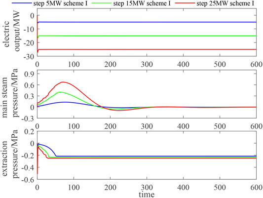
FIGURE 12. Control effect diagram of scheme I with the same PID parameters under the pure condensation condition.
Conclusion
In this paper, the dynamic characteristic simulation model of the CHP unit based on working point linearization is established, and the open-loop characteristics of the variable load process are analyzed by using the cooperation of improved particle swarm optimization control variables. Through the control strategy based on electrothermal cooperation and safety self-test, the closed-loop characteristics of unit dynamic regulation are studied, and the following conclusions are obtained:
1) When the control variable acts alone,
2) The closed-loop characteristic simulation of the control strategy based on electrothermal coordination and safety self-test shows that the electric power response speed and climbing rate are better, the peak value of pressure fluctuation is reduced by about 50%, and the recovery of extraction pressure closer to the steady-state value has less impact on heating.
3) Experiments on pure condensing and heating conditions with the same PID parameter show that the robustness of the conventional controller is strong enough to overcome the influence of modeling nonlinearity at different working points and adapt to the normal load variation range of the unit.
Data Availability Statement
The original contributions presented in the study are included in the article/Supplementary Material; further inquiries can be directed to the corresponding author.
Author Contributions
YH put forward the main research points. QC completed manuscript writing and mathematical analysis. JY contributed to the framework formation and revision. TL completed the simulation research.
Funding
This work was supported by the National Natural Science Foundation of China (52007103) and Research Fund for Excellent Dissertation of China Three Gorges University (2021BSPY013).
Conflict of Interest
The authors declare that the research was conducted in the absence of any commercial or financial relationships that could be construed as a potential conflict of interest.
Publisher’s Note
All claims expressed in this article are solely those of the authors and do not necessarily represent those of their affiliated organizations, or those of the publisher, the editors and the reviewers. Any product that may be evaluated in this article, or claim that may be made by its manufacturer, is not guaranteed or endorsed by the publisher.
Supplementary Material
The Supplementary Material for this article can be found online at: https://www.frontiersin.org/articles/10.3389/fenrg.2021.815272/full#supplementary-material
References
Beerends, R. J., ter Morsche, H. G., van den Berg, J. C., and Van de Vrie, E. M. (2003). Fourier and Laplace Transforms. Cambridge: Cambridge University Press.
Chen, Z., Yuan, X., Ji, B., Wang, P., and Tian, H. (2014). Design of a Fractional Order PID Controller for Hydraulic Turbine Regulating System Using Chaotic Non-dominated Sorting Genetic Algorithm II. Energ. Convers. Manage. 84, 390–404. doi:10.1016/j.enconman.2014.04.052
Deng, T., Tian, L., and Liu, J. (2017). Thermal and Electric Load Coupling Analysis and Decoupling Coordinated Control in Heat Supply Units. J. Syst. Simulation 29 (10), 2593–2599. doi:10.16182/j.issn1004731x.joss.201710046
Fu, W., Li, J., Wang, L., Shi, Y., and Yang, Y. (2017). Optimal Design for Thermodynamics System of Double Reheat Coal-Fired Power Plants with post-combustion Carbon Capture Based on Dynamic Adaptive Particle Swarm Optimization. Proc. CSEE 37 (9), 2652–2659. doi:10.13334/j.0258-8013.pcsee.161456
Gao, Y., and Tian, L. (2020). Thermal and Electric Load Decoupling Control of Heat Supply Units. J. North China Electric Power Univ. (Natural Sci. Edition) 47 (1), 87–95.
Gao, Y., and Yan, P. (2017). Dynamic Economic Dispatch of Wind Power Integrated System with Fully Developed Supply Responses of thermal Units. Proc. CSEE 37 (9), 2491–2499. doi:10.13334/j.0258-8013.pcsee.160468
Hooman, F., and Randolph, R. (2020). A Method for Inverting the Laplace Transforms of Two Classes of Rational Transfer Functions in Control Engineering. Alexandria Eng. J. 59 (6), 4879–4887. doi:10.1016/j.aej.2020.08.052
Li, Z., Jiang, W., Abu-Siada, A., Li, Z., Xu, Y., and Liu, S. (2021). Research on a Composite Voltage and Current Measurement Device for HVDC Networks. IEEE Trans. Ind. Electron. 68 (9), 8930–8941. doi:10.1109/tie.2020.3013772
Liu, J., Tian, L., Zeng, D., and Liu, X. (2005). Analysis on the Nonlinearity of Load-Pressure Characteristics of a 660MW Unit. J. Power Eng. 25 (4), 533–540. doi:10.3969/j.issn.1674-7607.2005.04.017
Liu, S., Zhou, C., Guo, H., Shi, Q., Song, T. E., Schomer, I., and Liu, Y. (2021). Operational Optimization of a Building-Level Integrated Energy System Considering Additional Potential Benefits of Energy Storage. J. Prot. Control. Mod. Power Syst. 6 (1), 1–10. doi:10.1186/s41601-021-00184-0
Liu, X., Tian, L., Wang, Q., and Liu, J. (2014). Simplified Nonlinear Dynamic Model of Generating Load-Throttle Pressure-Extraction Pressure for Heating Units. J. Chin. Soc. Power Eng. 34 (2), 115–121. doi:10.3969/j.issn.1674-7607.2014.02.006
Shen, X., Ouyang, T., Khajorntraidet, C., Li, Y., Li, S., and Zhuang, J. (2021). Mixture Density Networks-Based Knock Simulator. Ieee/asme Trans. Mechatron., 1. doi:10.1109/TMECH.2021.3059775
Shen, X., Ouyang, T., Yang, N., and Zhuang, J. (2021). Sample-based Neural Approximation Approach for Probabilistic Constrained Programs. IEEE Trans. Neural Netw. Learn. Syst., 1–8. doi:10.1109/TNNLS.2021.3102323
Shen, X., and Raksincharoensak, P. (2021). Pedestrian-aware Statistical Risk Assessment. IEEE Trans. Intell. Transport. Syst., 1–9. doi:10.1109/TITS.2021.3074522
Shen, X., and Raksincharoensak, P. (2021). Statistical Models of Near-Accident Event and Pedestrian Behavior at Non-signalized Intersections. J. Appl. Stat., 1–21. doi:10.1080/02664763.2021.1962263
Shen, X., Zhang, X., Ouyang, T., Li, Y., and Raksincharoensak, P. (2020). Cooperative Comfortable-Driving at Signalized Intersections for Connected and Automated Vehicles. IEEE Robot. Autom. Lett. 5 (4), 6247–6254. doi:10.1109/LRA.2020.3014010
Shen, X., Zhang, Y., Sata, K., and Shen, T. (2020). Gaussian Mixture Model Clustering-Based Knock Threshold Learning in Automotive Engines. Ieee/asme Trans. Mechatron. 25 (6), 2981–2991. Dec. doi:10.1109/TMECH.2020.3000732
Shen, X., Zhang, Y., Shen, T., and Khajorntraidet, C. (2017). Spark advance Self-Optimization with Knock Probability Threshold for Lean-Burn Operation Mode of SI Engine. Energy 1223, 1–10. doi:10.1016/j.energy.2017.01.065
Sun, H., Pan, Z., Sun, Y., Li, B., and Guo, Q. (2021). Reflection and Understanding of Application of Transboundary Thinking in Energy Internet. Automation Electric Power Syst. 45 (16), 63–72. doi:10.7500/AEPS20210323008
Tian, L., Lian, H. Q., Liu, X. P., and Liu, J. (2017). Coupling Characteristics of Steam Pressure and Intermediate Point Temperature for Once-Through Boiler. Proc. CSEE 37 (4), 1142–1150. doi:10.13334/j.0258-8013.pcsee.152321
Tian, L., Liu, F., Liu, X., and Liu, J. (2015). Parameter Optimization on Coordinated Control System of Thermal Power Units in High Rate Variable Load Operation Mode. J. Syst. Simulation 27 (7), 1532–1540. doi:10.16182/j.cnki.joss.2015.07.017
Tian, L. (2005). Research of Unit Plant Nonlinearity Dynamic model. Beijing: North China Electric Power University.
Wang, Q. (2013). Research on Optimization Control for Heating Units under the Condition of Large-Scale Integration of Wind power. Beijing: North China Electric Power University.
Wang, W., Sun, Y., Liu, J., et al. (2018). Load-change Control Strategy for Combined Heat and Power Units Adapted to Rapid Frequency Regulation of Power Grid. Automation Electric Power Syst. 42 (21), 63–69.
Wang, W., Jing, S., Sun, Y., Liu, J., Niu, Y., Zeng, D., et al. (2019). Combined Heat and Power Control Considering thermal Inertia of District Heating Network for Flexible Electric Power Regulation. Energy 169, 988–999. doi:10.1016/j.energy.2018.12.085
Wang, Z. Q. (2012). Fast Solving Strategies for Dynamic Optimization with Differential-Algebraic equations. Hangzhou: Zhejiang University.
Yang, J., Zhang, N., and Kang, C. (2020). Analysis Theory of Generalized Electric Circuit for Multi-Energy Networks—Part One branch Model. Automation Electric Power Syst. 44 (9), 21–32.
Yang, N., Ye, D., Zhou, Z., Cui, J., Chen, D., and Wang, X. (2018). Research on Modelling and Solution of Stochastic SCUC under AC Power Flow Constraints[J]. IET Generation, Transm. Distribution 12 (15), 3618–3625.
Yang, N., Huang, Y., Hou, D., Liu, S., Ye, D., Dong, B., et al. (2019). Adaptive Nonparametric Kernel Density Estimation Approach for Joint Probability Density Function Modeling of Multiple Wind Farms. Energies 12, 1356. doi:10.3390/en12071356
Yang, N., Liu, S., Deng, Y., and Xing, C. (2021). An Improved Robust SCUC Approach Considering Multiple Uncertainty and Correlation. IEEJ Trans. Elec Electron. Eng. 16, 21–34. doi:10.1002/tee.23265
Ye, J., Zhao, D., Zhang, L., Li, Z., and Zhang, T. (2012). “Research on Combined Electricity and Heating System Scheduling Method Considering Multi-Source Ring Heating Network,” in Front. Energy Res. 9:800906. doi:10.3389/fenrg.2021.800906
Zhang, L., Xie, Y., Ye, J., Xue, T., Cheng, J., Li, Z., et al. (2021). Intelligent Frequency Control Strategy Based on Reinforcement Learning of Multi-Objective Collaborative Reward Function. Front. Energ. Res. 9. doi:10.3389/fenrg.2021.760525
Zhang, W., Wang, X., Li, Y., and Qian, T. (2018). An Analysis Model of Multi-Area Interconnected Power Systems with Large-Scale Wind Power Involved in Comprehensive Heating and Power System Scheduling. Power Syst. Tech. 42 (1), 154–161. doi:10.13335/j.1000-3673.pst.2017.1559
Keywords: working point linearization, unit variable load, multivariable cooperative control, dynamic adaptive particle swarm optimization, dynamic regulation characteristics
Citation: Huang Y, Chen Q, Ye J and Lu T (2022) Study on Dynamic Process Characteristics of CHP Unit With Variable Load Based on Working Point Linearization Modeling. Front. Energy Res. 9:815272. doi: 10.3389/fenrg.2021.815272
Received: 15 November 2021; Accepted: 07 December 2021;
Published: 04 February 2022.
Edited by:
Yahui Zhang, Yanshan University, ChinaReviewed by:
Yuanchao Hu, Shandong University of Technology, ChinaGuangzheng Yu, Shanghai University of Electric Power, China
Copyright © 2022 Huang, Chen, Ye and Lu. This is an open-access article distributed under the terms of the Creative Commons Attribution License (CC BY). The use, distribution or reproduction in other forums is permitted, provided the original author(s) and the copyright owner(s) are credited and that the original publication in this journal is cited, in accordance with accepted academic practice. No use, distribution or reproduction is permitted which does not comply with these terms.
*Correspondence: Qing Chen, Y2hlbnFpbmcyMDE5MDgwOEAxNjMuY29t
 Yuehua Huang
 Qing Chen