 Na Liu
 Qian Zhao
- School of Environmental and Municipal Engineering, Qingdao University of Technology, Qingdao, China
Despite of the large number of research dedicated to condensation heat transfer and pressure drop characteristics in pristine micro-fin tubes, experimental investigation on effects of tube expansion have not been reported in the open literature. The paper reports measured cross-sectional dimensions, condensation heat transfer and pressure drop data of R1234ze(E) in pristine (5.10 mm OD) and expanded (5.26 mm OD) micro-fin tubes with mass fluxes from 100 to 300 kg/(m2·s). Effects of mass flux, vapor quality and tube expansion on the heat transfer coefficients and friction pressure gradients were investigated in the study. When the mass flux is 100 kg/(m2·s), the heat transfer coefficient and pressure drop of R1234ze(E) decrease after tube expansion. However, when the mass fluxes are 200 and 300 kg/(m2·s), tube expansion effects on the heat transfer coefficient and pressure drop are not notable. In addition, the experimental results are analyzed based on the existing condensation heat transfer and pressure drop correlations.
Introduction
Since the invention of Fujie et al. (1977), micro-fin tubes have been widely used in refrigeration and air-conditioning systems for high heat transfer and relatively low pressure drop performance. For finned tube heat exchangers, micro-fin tubes and the external fins must have a metal-to-metal interference fit to decrease the contact thermal resistance. Mechanical tube expansion process is used to expand the tube outside diameter which is forced against the external fin collar leading to an interference fit. The tube internal enhancements will be deformed or crushed to varying degrees for the mechanical expanding effect. The internal surface area of the micro-fin tube will also be affected by tube expansion. Therefore, tube expansion may cause the negative effect on the thermal-hydraulic performance of finned tube heat exchangers.
Many investigations on the thermal-hydraulic performance during condensation of different refrigerants in pristine micro-fin tubes with a variety of enhancements have been conducted by various researchers (Cavallini et al., 2009; Colombo et al., 2012; Dalkilic and Wongwises, 2009; Doretti et al., 2013; Lee et al., 2014; Liebenberg and Meyer, 2008; Wu and Sundén, 2016; Wu et al., 2014; Wu et al., 2015). The direct use of the condensation heat transfer and pressure drop results based on the pristine micro-fin tubes without any modification may cause deviation for the actual thermal-hydraulic performance of the heat exchangers. Therefore, the tube expansion effect on the micro-fin tube internal surface, heat transfer coefficient and pressure drop are of great significance to be investigated.
Among the few investigations referring to tube expansion in the existing literature, Tang et al. (2009) studied the expansion forming of inner grooved tubes and effects of the geometrical parameters of the groove geometry on forming quality. Experiments using different fin type tubes were conducted in their study. A finite element model of the forming process was established in the study. The results showed that the fin height reduced by approximately 5–9%. The fin geometric parameter effects on the fin height reduction were studied. The study showed that the helix angle had an important influence on the fin height reduction and the fin height ratio played a significant role in affecting the deformation resistant force. However, the effect of the fin deformation on the inner wall area was not investigated.
Mehendale (2013) analyzed the tube expansion effect on the inner wall area changes and evaluated the existing in-tube heat transfer correlations during condensation. A method for estimating the effect of tube expansion on the in-tube heat transfer performance during condensation was reported. The results showed that the in-tube heat transfer performance of copper and aluminum tubes reduced by 9–36% after the tube expansion. The fin number and the fin apex angle effects on in-tube thermal performance during condensation were also analyzed for expanded micro-fin tubes. Moreover, Mehendale (2014) also numerically investigated the fin deformation influence on the refrigerant side thermal-hydraulic performance of R410A during boiling in micro-fin tubes.
To the author’s knowledge, experimental studies on the effect of tube expansion on the heat transfer and pressure drop characteristics during condensation in micro-fin tubes are not available in the public literature. Therefore, the effects of tube expansion on thermal-hydraulic performance during condensation of R1234ze(E) in pristine and expanded micro-fin tubes were experimentally studied in the present study.
Experimental Apparatus and Procedures
Experimental Apparatus
Figure 1 shows the schematic diagram of the experimental apparatus established for two-phase flow and heat transfer experiments in micro-fin tubes. The experimental apparatus consists of a refrigerant and two cooling water circuits. The subcooled refrigerant in the reservoir is filtered, circulates through the magnetic-driven gear pump that can be adjusted by the frequency converter, and then flows through the Coriolis effect mass flowmeter. By adjusting the power of the preheater, the subcooled refrigerant is heated to the required inlet mass quality and temperature. The electric insulation heating wire is wound on the surface of the stainless-steel tube in the preheater. Glass fiber insulation and rubber foam insulation is used in the preheater. The mass quality of the refrigerant flowing into the test section is known. The refrigerant is condensed by the countercurrent cooling water in the test section. The refrigerant is fully condensed and subcooled by the cooling water in the sub-cooler. The sub-cooler is a shell-and-tube heat exchanger. The refrigerant flows on the tube side, and the water flows on the shell side. Afterwards, the refrigerant goes into the reservoir.
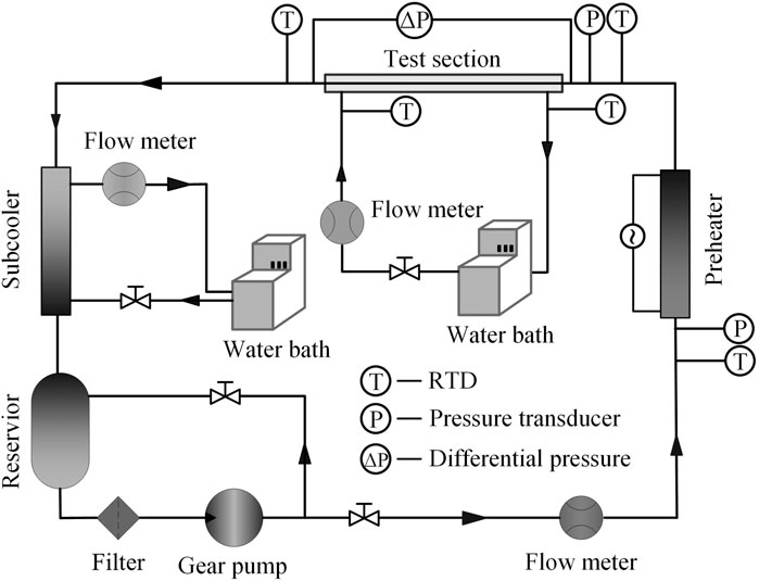
FIGURE 1. Schematic diagram of the experimental apparatus.
The cooling water circuit of the test section is composed of a constant temperature water bath, a Coriolis mass flowmeter and a regulating valve. The cooling water flows in the annular area of the test section to condensate the refrigerant. The mass flow of the cooling water is controlled by the regulating valve and measured by the mass flowmeter. The inlet temperature of the cooling water in the test section is kept at 20°C. The cooling water flow rate was adjusted to ensure the inlet and outlet cooling water temperature difference in the test section larger than 1 K and the experimental uncertainty of the heat transfer rate lower than ±10%.
Experimental Method and Condition
The refrigerant and cooling water temperatures are measured using PT100 resistance thermometers. Outer wall temperatures of the micro-fin tube are measured by eight copper-constantan thermocouples installed at two locations as shown in Figure 2. Thermocouples are evenly arranged on the upper, lower, and left and right sides of the outer wall of the micro-fin tube. Small slits are prepared carefully on the micro-fin tubes. Thermocouples are first welded to the surface and then surrounded with epoxy resin to avoid the effect of the cooling water in the test section. All the thermocouples and RTDs were calibrated before the experiments. Mixers were set before each fluid temperature measurement point to ensure that the fluids were fully mixed. The saturation states at the test section inlet and outlet were checked using the measured temperature and pressure. The average saturation temperature between the test section inlet and outlet was used to calculate the heat transfer coefficients. Trafag 8,251 pressure sensors are used to measure the refrigerant pressures through 1.0 mm pressure taps. The pressure drop of the refrigerant in the test section is measured through an EJA110A differential pressure sensor. Two Coriolis mass flowmeters are used to measure the mass flow rates of the refrigerant and the cooling water in the test section, respectively. The refrigerant temperature and pressure are used to ensure the saturation state at the entrance and exit of the test section. When all the temperatures, pressures and mass flow rates of the refrigerant and the cooling water keep constant for half an hour, the system is considered to reach a steady state. Experimental data are monitored and collected by an Agilent 34970A acquisition system with three 34901A cards at steady state. Table 1 listed the experimental conditions in the study.
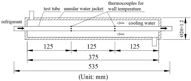
FIGURE 2. Schematic diagram of the test section.
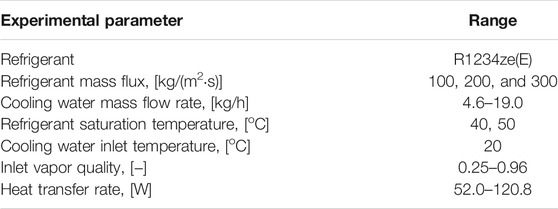
TABLE 1. Experimental conditions.
Test Section
The test section is a counter-flow tube-in-tube heat exchanger as illustrated in Figure 2. The refrigerant flows in the micro-fin tube, and the cooling water flows in the annular space. The length of the micro-fin tube is 535 mm and the length of the heat exchange section is 375 mm. The outer tube of the test section is a stainless-steel tube with outer diameter of 20 mm and wall thickness of 1.2 mm. Through considering the critical thermal insulation layer thickness, the insulation layer was set thick enough to weaken the heat loss in the test section. Besides, the aluminum foil was also used to reduce the radiation heat transfer between the outside wall of the test section and the external environment. In order to reduce the heat loss to the environment, 45 mm thick rubber foam insulation is used to wrap the entire experimental apparatus.
The test tubes are two micro-fin tubes in the pristine and expanded states respectively. Before the mechanical tube expansion process, they are from the same production batch with the same diameter. The pristine micro-fin tube is the raw material for residential air-conditioners. The expanded micro-fin tube is torn down from a residential air-conditioner which was mechanically expanded by a mandrel. Figure 3 shows geometrical parameters of the micro-fin tubes. The outer diameters of the micro-fin tubes are measured by a vernier caliper and the micro-fin geometrical parameters are measured by Hitachi SU8010 scanning electron microscope with a resolution of 1.3 nm. The outer diameter and micro-fin geometrical parameters were measured several times in three various positions of the test tubes and average values were obtained as listed in Table 2. The outer diameter, the fin root diameter, the fin apex angle and the tube cross-sectional area increased by 3.14, 4.31, 97.50, and 7.92% after the tube expansion process, while the wall thickness, the fin height and the area enhancement ratio (the total surface area of the micro-fin tube (A) relative to the nominal inner area (Afr) based on the fin root diameter (dfr)) decreased by 8.7, 9.09, and 12.79%.
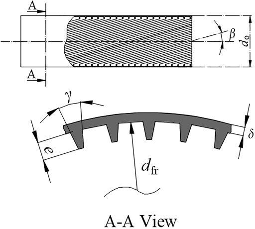
FIGURE 3. Geometrical parameters of the micro-fin tube.
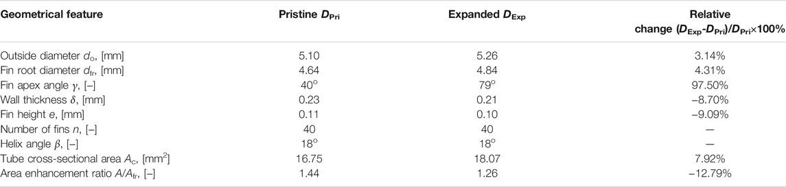
TABLE 2. Micro-fin tube dimensions.
Data Reduction and Uncertainty
The area enhancement ratio A/Afr can be expressed as (Webb and Kim, 2005)
Based on the heat balance between the refrigerant side and the cooling water side,the heat transfer rate in the test section is calculated as
The vapor quality of the refrigerant at the entrance of the test section, xin, can be calculated as
The vapor quality change, Δx, is calculated as
The average vapor quality of the refrigerant in the test section, xave, is calculated as
The outer wall temperature of the micro-fin tube is calculated as
The temperature difference between the inner and outer walls of the micro-fin tube is calculated as
The heat transfer coefficient at the refrigerant side, h, can be calculated as
Since the micro-fin tube is placed horizontally, the contribution of gravity is not considered. Therefore, the total pressure drop Δptotal of the refrigerant in the test section is calculated as
The accelerated pressure drop, Δpa, is calculated using the model recommended by Carey (2020).
The friction pressure drop gradient is expressed as
There are various void fraction models for smooth tubes in the public literature. However, there is no void fraction model specifically for micro-fin tubes. The void fraction model of smooth tubes is generally used for the micro-fin tube. The experimental study by Newell and Shah (2001) showed that void fraction of two micro-fin tubes differed little from that of the smooth tube. Figure 4 shows the void fraction comparison among the homogeneous model, the Zivi (1964) model, the Baroczy (1966) model. and the Smith (1969) model for R1234ze(E) at 40°C. The void fraction of the homogeneous model is less than the void fraction of the three separated flow models. The maximum mean absolute deviations between the separated models for R1234ze(E) are 0.037. The small difference in the void fraction has little effect on the accelerated pressure drop. The Zivi (1964) model is used to calculated the accelerated pressure drop in the study.

FIGURE 4. Comparison of void fraction between different models.
The thermophysical properties of R1234ze(E) are obtained through the REFPROP software (Lemmon et al., 2010). The experimental uncertainties of the parameters listed in Table 3 are analyzed using the method of Kline and McClintock (1953).
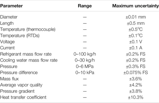
TABLE 3. Experimental uncertainties.
Results and Discussion
In order to verify the reliability of the experimental system, single-phase heat transfer experiment of R1234ze(E) was conducted in 5.10 mm OD micro-fin tube. The Reynolds number ranges from 2.8×10³ to 1.2×10⁴, and the inlet temperature of R1234ze(E) ranges from 35 to 39°C. The inlet temperature and flow rate of the cooling water in the test section are 15°C and 9.5°kg/h respectively. The deviation of the heat exchange between the refrigerant side and the cooling water side of the experimental section is within 5%.
The experimental results of single-phase heat transfer are in good agreement with the prediction results of Ravigururajanh (1986) with the absolute average deviation of 10.6%. Single-phase verification experiments show that the experimental apparatus is reliable and can be used for two-phase flow and condensation heat transfer experiments.
Heat Transfer Coefficient
In refrigeration and air conditioning systems, the mass flux of the refrigerant usually ranges from 100 to 500 kg/(m2·s). The mass flux of the refrigerant is taken as 100, 200 and 300 kg/(m2·s) in this study. Figure 5 shows the heat transfer coefficients of R1234ze(E) in pristine and expanded micro-fin tubes. The results show that the heat transfer coefficient increases with the increase of mass flux and vapor quality. The influence of vapor quality on the heat transfer coefficient increases with the increase of mass flux.
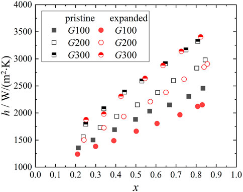
FIGURE 5. Heat transfer coefficients in pristine and expanded micro-fin tubes.
The convection heat transfer between the refrigerant and the inner wall of the micro-fin tube is enhanced with the increase of mass flux resulting in larger heat transfer coefficients. Since the heat conduction resistance of the liquid film plays a leading role in the condensation heat transfer, the thickness and heat conduction resistance of the liquid film decrease with the increase of vapor quality resulting in larger heat transfer coefficients.
The heat transfer coefficients of the pristine micro-fin tube and the expanded micro-fin tube are compared to study the influence of tube expansion. When the mass flux is 100 kg/(m2·s), the heat transfer coefficients in the pristine micro-fin tube are greater than those in the expanded micro-fin tube. When the mass flux is 200 and 300 kg/(m2·s), tube expansion has little effect on the heat transfer coefficient.
Micro-fins are used to redistribute the condensate film and maintain a thin film along the tube wall, thereby increasing the heat transfer coefficient. The redistribution effect will be weakened after the expansion process. During the expansion process, the internal fins of the tube underwent an amount of deformation, i.e., the fin apex angle increased while the fin height and the inner surface heat exchange area decreased as listed in Table 2, which degraded the fluid turbulence, surface tension induced drainage and the in-tube thermal performance during condensation. It is well known that micro-fins are effective at low mass fluxes, in which the stratified flow dominates, and which can be responsible for the tube expansion effect. Therefore, the tube expansion process degraded the in-tube thermal performance during condensation of R1234ze(E) at low mass flux (G = 100 kg/(m2·s)) in the present study.
The prediction deviations of the existing correlations (Yu and Koyama, 1998; Kedzierski and Goncalves, 1999; Cavallini et al., 1999; Cavallini et al., 2009) for the present heat transfer coefficients are analyzed in the study, and the results are shown in Figure 6. The performance of each correlation is evaluated according to the arithmetic mean deviation of relative residuals of heat transfer coefficient, a.m, and the root mean square deviation of the relative residuals of heat transfer coefficient, r.m.s, which is defined as follows:
where a represents to the heat transfer coefficient h or friction pressure gradient (dp/dz)f and N is the number of experimental data. Figure 6 indicates that (Kedzierski and Goncalves, 1999 correlation can predict the data well with 22.8% r.m.s errors for R1234ze(E). Prediction deviation of Yu and Koyama (1998) correlation for R1234ze(E) is 20.9%, while that of Cavallini et al. (2009) correlation is 39.2%. Though Cavallini et al. (1999) could predict the trend of the present heat transfer coefficients well, the predictions are lower than the data of R1234ze(E) by 69.4%. Prediction deviations for the present data by Cavallini et al. (1999) correlation may be due to the low fin height (0.11 mm) and the small tube outer diameter (5.10 mm) of the micro-fin tube. According to Cavallini et al. (2009), the height of the micro-fin of the previous micro-fin tube is 0.2–0.25 mm, and the outer diameter of the tube is generally greater than 9.5 mm. Cavallini et al. (1999) correlation, which was established based on those configurations as database, may therefore be limited.
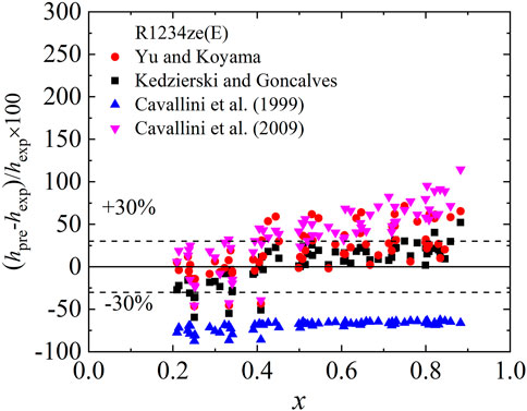
FIGURE 6. Comparison of predicted and experimental heat transfer coefficients.
Friction Pressure Drop
Figure 7 shows all the pressure drop components of R1234ze(E) at mass flux of 100 kg/(m2·s) in the expanded micro-fin tube. The measured total pressure drop, the acceleration pressure drop and the friction pressure drop all increase with the increase of vapor quality. The acceleration pressure drops for all the experimental conditions are within 14.1% for R1234ze(E) of the total pressure drops in the present study. In this study, the friction pressure gradient was analysed.
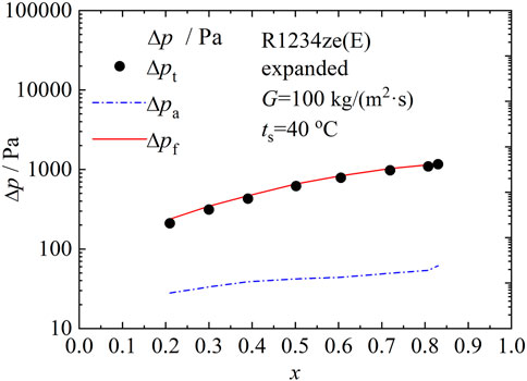
FIGURE 7. Pressure drop components in the expanded micro-fin tube.
Figure 8 shows the friction pressure gradients of R1234ze(E) in the expanded micro-fin tube. The mass fluxes are 100, 200 and 300 kg/(m2·s) with the saturation temperature of 40°C. The experimental data shows that the friction pressure gradient increases with the increase of mass flux and vapor quality, which is the general trend of the friction pressure gradient (Collier and Thome, 1994). As the mass flux increases, the vapor quality dependence of the heat transfer coefficient also becomes stronger. The shear stress at the two-phase interface and the shear stress between the liquid film and the inner wall of the tube both increase with the increase of mass flow and vapor quality, resulting in a greater friction pressure gradient.
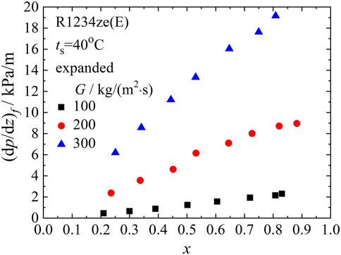
FIGURE 8. Friction pressure gradients in the expanded micro-fin tube.
In Figures 9, 10, 11, friction pressure gradients of the pristine micro-fin tube along with those of the expanded micro-fin tube for R1234ze(E) are compared to show effects of tube expansion for a given mass flux. At low mass flux [G = 100 kg/(m2·s)] shown in Figure 9, friction pressure gradients of R1234ze(E) in the expanded micro-fin tube decreased after the expansion process. The expansion effect was not notable at mass fluxes of 200 and 300 kg/(m2·s).
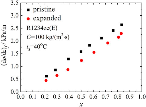
FIGURE 9. Effect of tube expansion on friction pressure gradients at 100 kg/(m2·s).
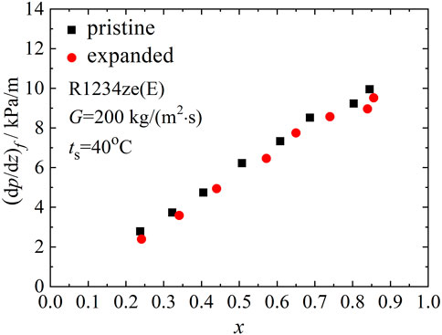
FIGURE 10. Effect of tube expansion on friction pressure gradients at 200 kg/(m2·s).
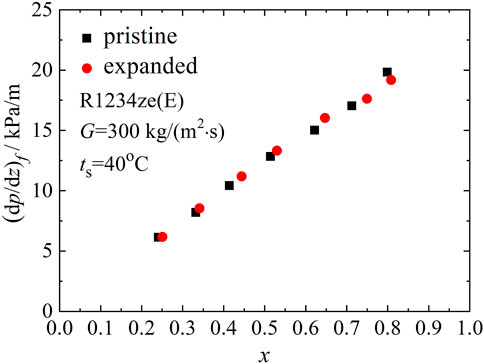
FIGURE 11. Effect of tube expansion on friction pressure gradients at 300 kg/(m2·s).
During the expansion process, the internal fins of the tube underwent an amount of deformation as listed in Table 2, which degraded the fluid turbulence and friction pressure gradients. The stratified flow was dominant at low mass flux, where tube expansion was effective in reducing the friction pressure gradient.
The experimental pressure gradients are compared with available correlations (Haraguchi et al. (1993); Kedzierski and Gonclaves, (1999); Choi et al. (1999); Goto et al., 2001), and the comparison are shown in Figure 12. Goto et al. (2001) correlation based on vapor-phase two-phase multiplier (Φv) is applied in the study. The comparison shows that Haraguchi et al. (1993), Kedzierski and Gonclaves (1999), Choi et al. (1999) and Goto et al. (2001) correlations predict the pressure gradients well.
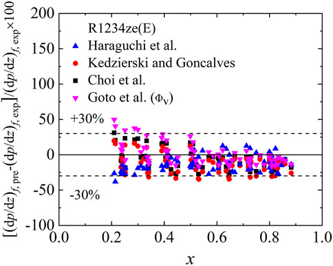
FIGURE 12. Comparison of predicted and experimental friction pressure gradients.
Conclusion
This paper reports experimental data during condensation of R1234ze(E) in pristine (5.10 mm OD) and expanded (5.26 mm OD) micro-fin tubes. In the study, the cross-sectional dimensions of the pristine and expanded micro-fin tubes are microscopically measured. The mass fluxes of the experiment are 100, 200, and 300 kg/(m2·s), the saturation temperature is 40°C, and the vapor qualities are from 0.1 to 0.9. Based on the research in this study, the following conclusions are obtained:
1 The outer diameter, the fin root diameter and the tube cross-sectional area of the micro-fin tube increased by 3.14, 4.31, and 7.92% after the tube expansion process, while the wall thickness, the fin height and the area enhancement ratio decreased by 8.70, 9.09, and 12.79%.
2 The heat transfer coefficients and friction pressure gradients increase with the increase of mass flux and vapor quality. The influence of vapor quality on the heat transfer coefficients and friction pressure gradients increases with the increase of mass flux.
3 At mass flux of 100 kg/(m2·s), the heat transfer coefficients and friction pressure gradients of R1234ze(E) decrease after the expansion process. At mass fluxes of 200 and 300 kg/(m2·s), tube expansion effects on the data are not notable for R1234ze(E).
4 The Kedzierski and Goncalves (1999) correlation predicts the heat transfer coefficients reasonably well of R1234ze(E). The pressure gradient data for R1234ze(E) is well predicted by Haraguchi et al. (1993), Kedzierski and Gonclaves (1999), Choi et al. (1999) and Goto et al. (2001) correlations.
Data Availability Statement
The original contributions presented in the study are included in the article/Supplementary Material, further inquiries can be directed to the corresponding author.
Author Contributions
NL established the experimental system, carried out the experiments and wrote the first submission of the paper. QZ and ZXL gave a lot of help during the experiments. All authors contributed to the article and approved the submitted version.
Funding
This work is supported by the National Natural Science Foundation of China (Grant No. 51904325).
Conflict of Interest
The authors declare that the research was conducted in the absence of any commercial or financial relationships that could be construed as a potential conflict of interest.
Publisher’s Note
All claims expressed in this article are solely those of the authors and do not necessarily represent those of their affiliated organizations, or those of the publisher, the editors and the reviewers. Any product that may be evaluated in this article, or claim that may be made by its manufacturer, is not guaranteed or endorsed by the publisher.
References
Baroczy, C. J. (1966). A Systematic Correlation for Two-phase Pressure Drop. Atomics Int. 62 (64), 232–249.
Carey, V. P. (2020). Liquid-vapor Phase-Change Phenomena: An Introduction to the Thermophysics of Vaporization and Condensation Processes in Heat Transfer Equipment. Boca Raton: CRC Press. doi:10.1201/9780429082221
Cavallini, A., Del Col, D., Mancin, S., and Rossetto, L. (2009). Condensation of Pure and Near-Azeotropic Refrigerants in Microfin Tubes: A New Computational Procedure. Int. J. Refrigeration 32 (1), 162–174. doi:10.1016/j.ijrefrig.2008.08.004
Choi, J. Y., Kedzierski, M. A., and Domanski, P. (1999). A Generalized Pressure Drop Correlation for Evaporation and Condensation of Alternative Refrigerants in Smooth and Micro-fin Tubes. Gaithersburg, USA: US Department of Commerce, Technology Administration, National Institute of Standards and Technology, Building and Fire Research Laboratory.
Collier, J. G., and Thome, J. R. (1994). Convective Boiling and Condensation. Chem. Eng. Sci. 28, 132–138.
Colombo, L. P. M., Lucchini, A., and Muzzio, A. (2012). Flow Patterns, Heat Transfer and Pressure Drop for Evaporation and Condensation of R134A in Microfin Tubes. Int. J. refrigeration 35 (8), 2150–2165. doi:10.1016/j.ijrefrig.2012.08.019
Dalkilic, A. S., and Wongwises, S. (2009). Intensive Literature Review of Condensation inside Smooth and Enhanced Tubes. Int. J. Heat Mass Transfer 52 (15-16), 3409–3426. doi:10.1016/j.ijheatmasstransfer.2009.01.011
Doretti, L., Rossetto, L., Longo, G. A., Cavallini, A., and Del Col, D. (1999). A New Computational Procedure for Heat Transfer and Pressure Drop during Refrigerant Condensation inside Enhanced Tubes. J. Enh Heat Transf 6 (6), 441–456. doi:10.1615/JEnhHeatTransf.v6.i6.50
Doretti, L., Zilio, C., Mancin, S., and Cavallini, A. (2013). Condensation Flow Patterns inside plain and Microfin Tubes: A Review. Int. J. Refrigeration 36 (2), 567–587. doi:10.1016/j.ijrefrig.2012.10.021
Fujie, K., Itoh, M., Innami, T., Kimura, H., Nakayama, W., and Yanagida, T. (1977). Heat Transfer Pipe (No. US 4044797).
Goto, M., Inoue, N., and Ishiwatari, N. (2001). Condensation and Evaporation Heat Transfer of R410A inside Internally Grooved Horizontal Tubes. Int. J. Refrigeration 24 (7), 628–638. doi:10.1016/S0140-7007(00)00087-6
Haraguchi, H., Koyama, S., Esaki, J., and Fujii, T. (1993). “Condensation Heat Transfer of Refrigerants HCFC134a, HCFC123 and HCFC22 in a Horizontal Smooth Tube and a Horizontal Micro-fin Tube,” Proceedings of the 30th National Symposium of Japan, Yokohama, Japan. 343–345.
Kedzierski, M. A., and Goncalves, J. M. (1999). Horizontal Convective Condensation of Alternative Refrigerants within a Micro-fin Tube. J. Enh Heat Transf 6 (2-4), 161–178. doi:10.1615/JEnhHeatTransf.v6.i2-4.90
Kline, S. J., and McClintock, F. A. (1953). Describing Uncertainties in Single-Sample Experiments. Mech. Eng. 75 (1), 3–8.
Lee, E. J., Kim, N. H., and Byun, H. W. (2014). Condensation Heat Transfer and Pressure Drop in Flattened Microfin Tubes Having Different Aspect Ratios. Int. J. refrigeration 38, 236–249. doi:10.1016/j.ijrefrig.2013.09.035
Lemmon, E. W., Huber, M. L., and McLinden, M. O. (2010). NIST Reference Fluid Thermodynamic and Transport Properties–REFPROP. NIST Stand. reference database 23, v9.
Liebenberg, L., and Meyer, J. P. (2008). A Review of Flow Pattern-Based Predictive Correlations during Refrigerant Condensation in Horizontally Smooth and Enhanced Tubes. Heat Transfer Eng. 29 (1), 3–19. doi:10.1080/01457630701677049
Mehendale, S. S. (2014). “The Impact of Fin Deformation on Boiling Heat Transfer and Pressure Drop in Internally Grooved Tubes,”in International Heat Transfer Conference Digital Library, Kyoto, Japan, August 10-15, 2014 (Begel House Inc). doi:10.1615/ihtc15.fbl.008800
Mehendale, S. (2013). “The Impact of Fin Deformation on Condensation Heat Transfer Coefficients in Internally Grooved Tubes,”in Heat Transfer Summer Conference, Minneapolis, Minnesota, USA, July 14–19, 2013 (American Society of Mechanical Engineers (ASME)), 55485, V002T07A002. doi:10.1115/HT2013-17111
Newell, T. A., and Shah, R. K. (2001). An Assessment of Refrigerant Heat Transfer, Pressure Drop, and Void Fraction Effects in Microfin Tubes. Hvac&r Res. 7 (2), 125–153. doi:10.1080/10789669.2001.10391267
Ravigururajan, T. S. (1986). General Correlations for Pressure Drop and Heat Transfer for Single-Phase Turbulent Flows in Ribbed Tubes. Doctoral dissertation. Iowa State University
Smith, S. L. (1969). Void Fractions in Two-phase Flow: a Correlation Based upon an Equal Velocity Head Model. Proc. Inst. Mech. Eng. 184 (1), 647–664. doi:10.1243/PIME_PROC_1969_184_051_02
Tang, D., Peng, Y., and Li, D. (2009). Numerical and Experimental Study on Expansion Forming of Inner Grooved Tube. J. Mater. Process. Tech. 209 (10), 4668–4674. doi:10.1016/j.jmatprotec.2008.11.037
Wu, Z., and Sundén, B. (2016). Frictional Pressure Drop Correlations for Single-phase Flow, Condensation, and Evaporation in Microfin Tubes. J. Heat Transfer 138 (2), 022901. doi:10.1115/1.4031268
Wu, Z., Sundén, B., Wadekar, V. V., and Li, W. (2015). Heat Transfer Correlations for Single-phase Flow, Condensation, and Boiling in Microfin Tubes. Heat Transfer Eng. 36 (6), 582–595. doi:10.1080/01457632.2014.939531
Wu, Z., Sundén, B., Wang, L., and Li, W. (2014). Convective Condensation inside Horizontal Smooth and Microfin Tubes. J. Heat transfer 136 (5), 051504. doi:10.1115/1.4026370
Yu, J., and Koyama, S. (1998). Condensation Heat Transfer of Pure Refrigerants in Microfin Tubes. International Refrigeration and Air Conditioning Conference. 431.
Zivi, S. M. (1964). Estimation of Steady-State Steam Void-Fraction by Means of the Principle of Minimum Entropy Production. J. Heat Transfer 86 (2), 247–251. doi:10.1115/1.3687113
Glossary
A refrigerant side surface area, m2
Ac channel cross-sectional area, m2
Afr channel surface area based on the fin root diameter, m2
dfr fin root diameter, m
do outside diameter, m
e fin height, m
G mass flux, kg/(m2·s)
h heat transfer coefficient, W/(m2·K)
i specific enthalpy, J/kg
ilv latent heat of vaporization, J/kg
I electric current, A
l effective heat transfer length, m
L micro-fin tube length, m
m mass flow rate, kg/s
n number of fins
U electric voltage, V
p pressure, Pa
pf rib pitch normal to the fins, m
Q heat transfer rate, W
t temperature, oC
x vapor quality
Greek symbols
α void fraction
β helix angle
γ apex angle
δ wall thickness, m
λ thermal conductivity, W/(m·K)
ρ density, kg/m3
Subscripts
ave average
c cooling water
exp expanded or experimental
f friction
i inner
l liquid
in inlet
o outer
out outlet
pri pristine
pre predicted
r refrigerant
v vapor
w wall
Keywords: micro-fin tube, tube expansion, condensation, heat transfer, pressure drop
Citation: Liu N, Zhao Q and Lan Z (2021) Effect of Tube Expansion on Heat Transfer and Pressure Drop Characteristics During Condensation in Micro-Fin Tubes. Front. Energy Res. 9:811054. doi: 10.3389/fenrg.2021.811054
Received: 08 November 2021; Accepted: 19 November 2021;
Published: 02 December 2021.
Edited by:
Huaqing Xie, Northeastern University, ChinaReviewed by:
Jie Sun, Beijing University of Technology, ChinaHui Han, China University of Petroleum (Huadong), China
Qiang Li, Heilongjiang Bayi Agricultural University, China
Copyright © 2021 Liu, Zhao and Lan. This is an open-access article distributed under the terms of the Creative Commons Attribution License (CC BY). The use, distribution or reproduction in other forums is permitted, provided the original author(s) and the copyright owner(s) are credited and that the original publication in this journal is cited, in accordance with accepted academic practice. No use, distribution or reproduction is permitted which does not comply with these terms.
*Correspondence: Na Liu, bGl1bmFAcXV0LmVkdS5jbg==