- Department of Aerospace Science and Technology, Space Engineering University, Beijing, China
Self-excited high frequency combustion instability (HFCI) of first-order tangential (1T) mode was observed in a staged-combustion LOX/Kerosene liquid rocket engine numerically. Two different kinds of 1T patterns, standing wave mode and traveling wave mode, were captured in the present work. In the nominal operation condition, the ratio of oxygen-to-fuel (O/F) was 2.5. Propellant was evenly distributed in all injectors and no HFCI occurred. The chamber pressure obtained from the numerical simulation and experiment showed a good agreement, which validated the numerical model. When the mass flow of fuel for two injectors was modified, severe HFCI occurred. The pressure wave node was located at a fixed diameter, showing a 1T standing wave mode. As the O/F was set 4.4 and the propellant distribution was completely uniform, the numerical result yielded a 1T wave node featured a spinning behavior, which was a traveling 1T wave mode. Once the HFCI arose, no matter what standing mode or spinning mode, the pressure and heat release oscillated totally in phase temporally and coupled spatially. The heat release from combustion was fed into the resonant acoustic mode. This was the thermoacoustic coupling process that maintained the HFCI.
Introduction
HFCI remains an unresolved problem for the development of liquid rocket engines (LREs). Advanced heavy rocket engines are a prominent demand of farther space exploration. However, HFCI still acts as a big obstacle in the way since 1940s (Harrje, 1972; Culick and Yang, 1995). HFCIs have the characteristics of pressure oscillations at frequencies on the order of kilohertz, corresponding to the chamber’s resonant acoustic modes. HFCI is extraordinarily destructive, especially the 1T mode, which can destroy the cooling fluid film attached to the chamber wall and further give rise to extensive heat transfer to the injector faceplate and chamber wall (Dranovsky et al., 1994). Therefore, once the HFCI of 1T mode occurs, the combustion chamber would suffer a severe thermal load even completely be destroyed in some extreme conditions. As shown in Figure 1, there are three examples that LRE was damaged by HFCI.
Rayleigh Criterion (Rayleigh, 1878; Rayleigh and Nachtrieb, 1957) is a widely accepted and significant consensus used for explaining the maintaining mechanism of thermo-acoustic instability. Rayleigh thought that the time the pressure was at its peak was when heat was added to a system in an oscillatory cycle, as the oscillation would be encouraged and the amplitude would increase; but if the heat was extracted from the system when the pressure was at its peak value, the oscillation would be discouraged, and the amplitude would decrease. Almost every LRE suffered from HFCI during its development process, and the deep reason that results in HFCI has not been uncovered until now. Therefore, HFCI should be paid sufficient attention for its theoretical and engineering significance. The most firsthand and effective methods are the full-scale tests. Unfortunately, the full-scale tests are expensive and time-consuming, and thus impractical. When the development of a rocket engine is hampered by HFCIs, the approach usually taken is the trial-and-error procedures, like the development campaigns of F-1 engine of the Apollo project (Oefelein and Yang, 1993). There are over 2,000 full-scale engine tests with approximately 100 diverse injector designs were performed to solve the problems caused by HFCIs.
With the rapid growth of computer processing power, computational fluid dynamics (CFD) has become more prevalent in modeling combustion instabilities. Numerical simulation methods of different levels, from low to high fidelity, have been developed over the last decade. Tremendous efforts have been devoted to building reduced-order models (Frezzotti et al., 2018) and high-fidelity simulation models (Garby et al., 2013; Urbano et al., 2016).
Combined experimental and computational studies have shown a promising path for investigating combustion instabilities. A continuously variable resonance combustor (CVRC), developed at Purdue University specifically for the investigation of longitudinal combustion instability, has been studied both experimentally (Miller et al., 2007; Yu et al., 2012) and numerically (Harvazinski et al., 2015). The results indicated that combustion instability was associated with periodic vortex shedding. Subsequently, a seven-element (Pomeroy and Anderson, 2016; Popov and Sirignano, 2016) and a nine-element (Orth et al., 2018; Gejji et al., 2020) sub-scale rocket combustor was designed to boost self-excited transverse instabilities. In-depth numerical simulations (Tudisco et al., 2016; Harvazinski et al., 2019) based on the experimental setup were performed. It was found that the mass flow rate of the outer injectors was altered by the transverse pressure waves resulting in a sudden heat release, which eventually triggered the transverse combustion instability. A multi-injector cryogenic propellant rocket combustor, characterized by 1T mode self-excited combustion instability, was conducted in the German Aerospace Center (Gröning et al., 2016; Hardi et al., 2016; Armbruster et al., 2020; Klein et al., 2020). Urbano et al. (2016) conducted a corresponding high-fidelity calculation, which is a landmark work for its high accuracy and enormous computing load. Both the experimental analysis and numerical results indicated that the 1T mode thermoacoustic instability was strongly coupled with oxidizer injectors.
In this paper, the HFCI of a Kero/LOX LRE is studied numerically based on OpenFOAM (Open Source Field Operation and Manipulation), and the mechanism of combustion instability is analyzed. Previous experiment research (Bibik et al., 2008a; Bibik et al., 2008b) has indicated that the 1T HFCI mode has two behaviors: standing wave and traveling wave. The work in this paper concentrates on detailing the mechanisms of the two patterns of 1T HFCI mode.
Numerical Simulation Model
In gas-liquid two-phase spray combustion, the most mainstream methods are Lagrange-drop and Eulerian-fluid (LDEF). In the LDEF frame, the gas phase is processed as a continuous medium while the liquid phase is treated as discrete particles, and the interaction between the gas phase and discrete particle phase is considered. In the current work, the oxidizer is gaseous while the fuel is liquid. Therefore, the gaseous oxidizer is modeled in a Eulerian framework, while the liquid fuel is modeled in a Lagrangian framework. Compressible Reynolds-averaged Navier-Stokes (RANS), the most widely used numerical simulation method in engineering, was adopted in this paper.
Governing Equations and CFD Solver
The CFD calculations were performed based on OpenFOAM, which is an open-source, object-oriented code developed by OpenCFD. In this work, the sprayFoam solver, a spray and combustion code, was used. Eulerian-Lagrangian simulation framework was adopted. The gas phase is solved in an Eulerian framework and governed by Navier-Stokes (N-S) equations with chemical reactions, where the equations are considered to be continuous in space and time. The general form of the governing equation, which is the conservative three-dimensional N-S equations in a rectangular coordinate system, is given as follows (Veynante and Vervisch, 2002).
Where
The liquid spray is modeled in a Lagrangian framework. A standard discrete droplet method (DDM) approach is used. To calculate the evolution of the location and velocity components of the parcels, a set of differential equations along the trajectory of each particle is solved. Each parcel stands for a class of identical and non-interacting droplets. To model interaction between discrete droplets and continuous phase, the parcels are tracked through the physical space in a Lagrangian manner based on the mass, momentum, and energy exchange with the gas phase. In the present work, the coneNozzleInjection model served as the injection model, where the atomization cone is set as 90° according to the experimental result. The Rosin-Rammler distribution model, as the most widely used model, was adopted with an average droplet diameter equal to 50 µm. The RanzMarshall model was used to model the droplet heat transfer. Meanwhile, the dispersive and break-up models were not considered.
Discretization Scheme and Solution of the Equation
The finite volume method (FVM) was adopted to discretize the governing equation mentioned above. For the strong nonlinear coupling of N-S equations, the coupling between pressure and velocity was modeled by the PIMPLE algorithm (Veynante and Vervisch, 2002). As for the discretization process for viscous terms and convective terms, interface interpolation with second-order precision was achieved with the central difference scheme and Van Leer scheme, respectively. The backward difference scheme with second-order precision is applied for the time term.
Chemical Reaction Mechanism
It is difficult to obtain an accurate chemical reaction process because kerosene is a mixture of hundreds of components. In this paper, C12H26 served as the alternative fuel and a single-step global chemical reaction mechanism is adopted to model the chemical reaction process. The chemical reaction rate is calculated by the following equation.
Where A is the pre-exponential factor, Ea is the activation energy, T is the temperature with unit K, and
Turbulent Model and Turbulent Combustion Model
Regarding the turbulent model, in consideration of calculated quantity, the standard
Mesh, Boundary Conditions, and Geometry Parameters
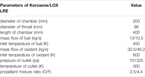
Unstructured mesh is used in paper, as is shown in Figure 2. The mesh contains about 1.38 million cells, and the region near the injector face is refined, since the chemical reaction takes place in this region. The boundary conditions of the computational domain are listed in Table 2. The geometrical parameters of the LRE and initial conditions in this work are detailed in Table 3.
Combustion Chamber Acoustic Theory
The LRE chamber can be simplified into a cylinder with two closed sides. The wave equation in the cylinder is given below (Yu et al., 2012).
Where
The intrinsic acoustic frequency of the combustion chamber is shown as follow (Huzel and Huang, 1992),
Where
Theoretically, there are two kinds of solution of tangential acoustic mode, they are standing wave solution and traveling wave solution, shown as Eqs 5, 6, respectively (Yang and Anderson, 1995).
Where
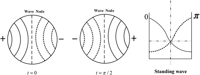
For the standing wave solution, the nodal diameter is located at a fixed position, and the standing wave 1T mode structure could be demonstrated by Figure 3. In the traveling wave solution, the nodal diameter is spinning around the center of the cycle. Its changing process is depicted in Figure 4.
Analysis of Numerical Simulation Results
There are three cases being calculated based on the numerical simulation model built in the present work: case1 is based on experimental conditions, while case2 and case3 are aimed at exploring two kinds of 1T HFCI mode.
Validation of Numerical Simulation Model
Under the nominal conditions, the mass flow rates of fuel and oxidizer are 13.0 kg/s and 32.5 kg/s, respectively, resulting in an O/F of 2.5. The chamber pressure under nominal conditions was about 12 MPa in the experimental test. The numerical simulation based on the experimental conditions is carried out. Propellant is evenly distributed to 91 injectors. The pressure-time history is shown in Figure 5 and the chamber pressure remained at 11.80 MPa, resulting in an error of 1.67% compared with its experimental counterpart. The error is reasonable and the validation of the numerical simulation model can be verified.
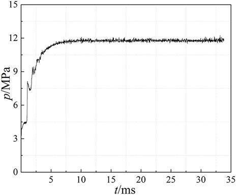
FIGURE 5. Numerical simulation based on experiment (probe is near the wall and 50 mm downstream from injector faceplate).
Standing Wave Pattern of 1T HFCI
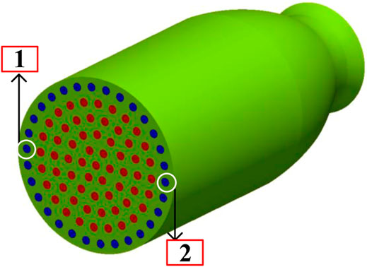
In case2, O/F = 2.5, and the only difference from case1 is that the fuel mass flow rate of No.1 and No.2 injectors in Figure 6 is changed. Half of the fuel for No.1 injector is allocated to No.2 injector. This non-uniform distribution leads to severe HFCI.
The pressure-time trace and its FFT (Fast Fourier Transform Algorithm) result are given in Figure 7. The probe location is 50 mm away from the injector faceplate and near the chamber wall. The dominant frequency is 3524 Hz. In case2, the chemical equilibrium acoustic velocity is 1145.3 m/s, which could be calculated by CEA (Chemical Equilibrium with Applications) from NASA (McBride and Gordon, 1996). The theoretical intrinsic frequency of 1T mode (according to Eq. 4) for case2 is 3729 Hz, and the difference between the numerical result and the theoretical value is 5.5%. Therefore, it is believed that 1T HFCI appears in case2 based on preliminary judgment.
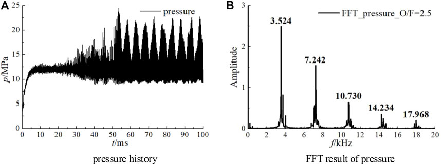
FIGURE 7. Pressure history and its FFT result of case2 (probe is near the wall and 50 mm downstream from injector faceplate). (A) pressure-time trace. (B) FFT result of pressure.
The pressure and heat-release evolution process within half an oscillation cycle in cross-section x = 50 mm are detailed in Figure 8. Where there is a pressure peak, there is a heat-release peak, so pressure and heat-release are coupled spatially. Pressure and heat-release peaks move along a diameter line back and forth, and the nodal diameter remains unchanged, so the HFCI is a standing mode in case2.
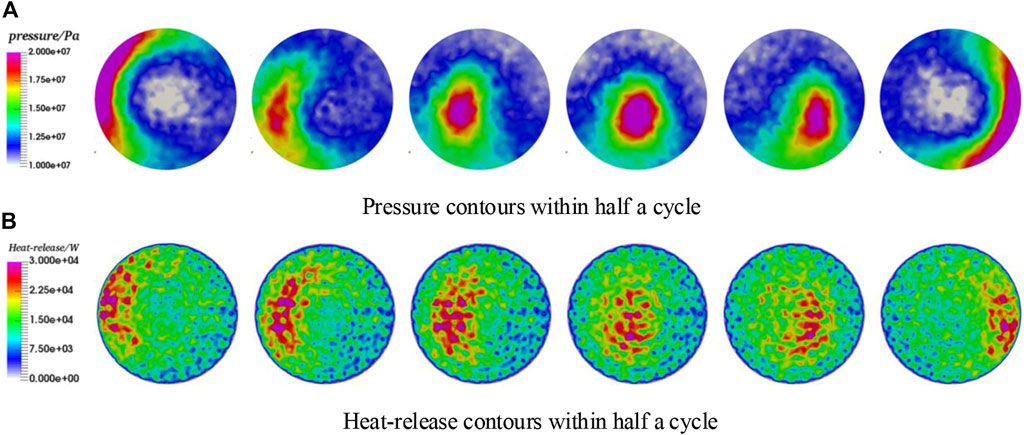
FIGURE 8. Pressure and heat-release changing process within half a period in case2. (A) Pressure contours within half a cycle. (B) Heat-release contours within half a cycle.
Figure 9 shows the temporal relationship between pressure and heat-release. Apparently, the pressure and heat-release oscillate in phase. What occurs in case2 is in accordance with the Rayleigh Criterion both spatially and temporally. By means of the pressure and heat-release contours and their temporal relationship, the thermal-acoustic coupling can be demonstrated more clearly.
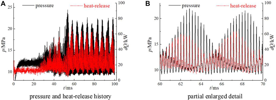
FIGURE 9. Relationship between pressure and heat-release in case2 (probe is near the wall and 50 mm downstream from injector faceplate). (A) pressure and heat-release history. (B) partial enlarged detail of (A).
Traveling Wave Pattern of 1T HFCI
When the value of O/F arrives at 4.4, and all 91 injectors share uniform propellants. A severe HFCI occurs, which is proven to be a traveling wave 1T mode. The pressure-time trace and FFT result are given in Figure 10.
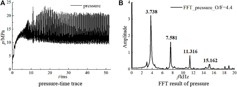
FIGURE 10. Pressure history and its FFT result of case2 (probe is near the wall and 50 mm downstream from injector faceplate). (A) pressure-time trace. (B) FFT result of pressure.
Obviously, the pressure-time trace indicates that it is an equal-amplitude oscillation, and the dominant frequency is 3738 Hz. The chemical equilibrium acoustic velocity is 1092.2 m/s, calculated by CEA, so the theoretical 1T frequency is 3556 Hz. The error between the numerical and theoretical values is 4.8%. Therefore, an initial judgment can be made that a 1T mode HFCI occurs when O/F value reaches 4.4.
Five probes in a transverse section (x = 50 mm, 50 mm away from injector faceplate) and their pressure-time traces are shown in Figure 11. The pressure of probe0, located at the center of the cycle, remains nearly constant, while the other 4 probes that are near the chamber wall show nearly constant amplitude. Two probes which are 180°apart (probe1 and probe3, probe2 and probe4) have reverse phase: when the pressure value of probe1 reaches the peak of the wave, the pressure value of probe3 nearly arrives at its lowest value. Also, it is clear that the pressure peak successively arrives at probe1→probe2→probe3→probe4→probe1. Therefore, a conclusion can be drawn that it is a spinning 1T HFCI mode and the direction of rotation is counter-clockwise. This conclusion can be proven further by the pressure and heat-release contours at the transverse section (x = 50 mm) within one cycle, and the contours are shown in Figures 12A,B.
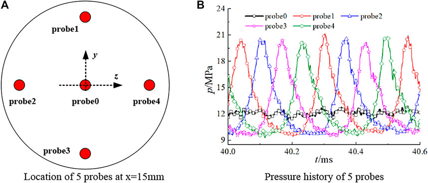
FIGURE 11. Pressure relationship of 5 probes at cross section x = 50 mm. (A) Location of 5 probes at x=15 mm. (B) Pressure history of 5 probes.
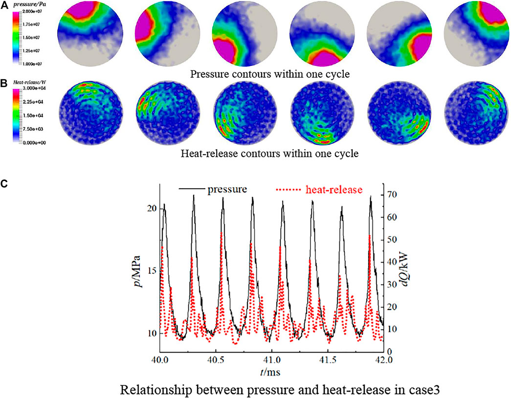
FIGURE 12. Pressure and heat-release changing process within one cycle in case3. (A) Pressure contours within one cycle. (B) Heat-release contours within one cycle. (C) Relationship between pressure and heat-release in case3.
An important feature is that the peak values of pressure and the heat-release always remain synchronous spatially. The relationship between pressure and heat-release in probe1 is shown in Figure 12C, and pressure and heat-release oscillate in phase. Obviously, the pressure and heat-release coupling process drives the HFCI.
Conclusion
From the numerical simulation results and analysis above, the following three conclusions were reached:
1. HFCI is sensitive to initial conditions. Compared with case1, a subtle change of propellant distribution in case2 leads to severe HFCI. The only difference between case1 and case2 is the injection distribution, Therefore, the comparison between case1 and case2 could indicate that the subtle change of propellant distribution exerts a significant effect on HFCI. The only difference between case1 and case3 is the operating condition (O/F). Therefore, the comparison between case1 and case3 could indicate that the O/F has a great influence on HFCI.
2. The two different 1T modes were captured numerically: standing mode with a constant nodal diameter and traveling mode with spinning nodal diameter.
3. Whether the 1T HFCI is in standing mode or traveling mode, the pressure and heat-release oscillated in phase both spatially and temporally, which accords with Rayleigh Criterion. It is the coupling process between pressure and heat-release that drives and maintains the thermo-acoustic instability.
Data Availability Statement
The raw data supporting the conclusion of this article will be made available by the authors, without undue reservation.
Author Contributions
KG’s main contributions were to the numerical simulation model and data processing. BX contributed primarily to data processing and writing the manuscript. YR and YT were the main contributors to the numerical simulation model. WN mainly provided financial support for the numerical simulation.
Funding
National Natural Science Foundation of China (Nos 12002386 and 51876219).
Conflict of Interest
The authors declare that the research was conducted in the absence of any commercial or financial relationships that could be construed as a potential conflict of interest.
Publisher’s Note
All claims expressed in this article are solely those of the authors and do not necessarily represent those of their affiliated organizations, or those of the publisher, the editors and the reviewers. Any product that may be evaluated in this article, or claim that may be made by its manufacturer, is not guaranteed or endorsed by the publisher.
Acknowledgments
The authors would like to express their sincere acknowledgments for the computing resources provided by Beijing Beilong Super Cloud Computing Co., Ltd.
References
Armbruster, W., Hardi, J. S., Miene, Y., Suslov, D., and Oschwald, M. (2020). Damping Device to Reduce the Risk of Injection-Coupled Combustion Instabilities in Liquid Propellant Rocket Engines. Acta Astronautica 169, 170–179. doi:10.1016/J.ACTAASTRO.2019.11.040
Bibik, O., Lubarsky, E., Shcherbik, D., and Hadjipanayis, M. (2008). Rotational Traveling of Tangential Wave in Multi-Injectors LRE Combustor Simulator. Availableat: https://academic.microsoft.com/paper/2471634577/.
Bibik, O., Lubarsky, E., Shcherbik, D., Hadjipanayis, M., and Zinn, B. (2008). Rotational Traveling of Tangential Wave in LRE Combustor Simulator. doi:10.2514/6.2008-1001
Culick, F. E. C., and Yang, V. (1995). Overview of Combustion Instabilities in Liquid-Propellant Rocket Engines.
Dranovsky, M. L., Yang, V., Culick, F. E. C., and Talley, D. G. (1994). Combustion Instabilities in Liquid Rocket Engines: Testing and Development Practices in Russia.
Frezzotti, M. L., Nasuti, F., Huang, C., Merkle, C. L., and Anderson, W. E. (2018). Quasi-1D Modeling of Heat Release for the Study of Longitudinal Combustion Instability. Aerospace Sci. Techn. 75, 261–270. doi:10.1016/J.AST.2018.02.001
Garby, R., Selle, L., and Poinsot, T. (2013). Large-Eddy Simulation of Combustion Instabilities in a Variable-Length Combustor. Comptes Rendus Mécanique 341, 220–229. doi:10.1016/j.crme.2012.10.020
Gejji, R., Lemcherfi, A. I., Strelau, R., Slabaugh, C. D., and Anderson, W. E. (2020). Combustion Response of Shear Coaxial Injectors to Transverse Combustion Instabilities. Orlando, FL: AIAA Scitech 2020 Forum. doi:10.2514/6.2020-0424
Gröning, S., Hardi, J. S., Suslov, D., and Oschwald, M. (2016). Injector-Driven Combustion Instabilities in a Hydrogen/Oxygen Rocket Combustor. J. Propulsion Power 32, 560–573. doi:10.2514/1.B35768
Hardi, J., Oschwald, M., Grning, S., Beinke, S., and Knapp, B. (2016). High Frequency Combustion Instabilities in Liquid Propellant Rocket Engines: Research Programme at DLR Lampoldshausen, Thermoacoustic Instabilities in Gas Turbines and Rocket Engines: Industry Meets AcademiaMunich. Germany. Availableat: https://www.researchgate.net/publication/312217154.
Harrje, D. T. (1972). Liquid Propellant Rocket Combustion Instability, SP-194. Washington, DC United States: NASA Headquarters.
Harvazinski, M. E., Gejji, R., Talley, D. G., Orth, M. R., Anderson, W. E., and Pourpoint, T. L. (2019). Modeling of Transverse Combustion Instability. California: AIAA Scitech 2019 ForumSan Diego. doi:10.2514/6.2019-1732
Harvazinski, M. E., Huang, C., Sankaran, V., Feldman, T. W., Anderson, W. E., Merkle, C. L., et al. (2015). Coupling between Hydrodynamics, Acoustics, and Heat Release in a Self-Excited Unstable Combustor. Phys. Fluids 27, 045102. doi:10.1063/1.4916673
Huzel, D. K., and Huang, D. H. (1992). Modern Engineering for Design of Liquid Propellant Rocket Engines.
Klein, S., Börner, M., Hardi, J. S., Suslov, D., and Oschwald, M. (2020). Injector-coupled Thermoacoustic Instabilities in an Experimental LOX-Methane Rocket Combustor during Start-Up. CEAS Space J. 12, 267–279. doi:10.1007/S12567-019-00294-4
McBride, B. J., and Gordon, S. (1996). Computer Program for Calculation of Complex Chemical Equilibrium Compositions and Applications, NASA-RP-1311.
Miller, K., Sisco, J., Nugent, N., and Anderson, W. (2007). Combustion Instability with a Single-Element Swirl Injector. J. Propulsion Power 23, 1102–1112. doi:10.2514/1.26826
Oefelein, J. C., and Yang, V. (1993). Comprehensive Review of Liquid-Propellant Combustion Instabilities in F-1 Engines. J. propulsion Power 9, 657–677. doi:10.2514/3.23674
Orth, M. R., Vodney, C., Liu, T., Hallum, W. Z., Pourpoint, T. L., and Anderson, W. E. (2018). Measurement of Linear Growth of Self-Excited Instabilities in an Idealized Rocket Combustor. doi:10.2514/6.2018-1185
Pomeroy, B., and Anderson, W. (2016). Transverse Instability Studies in a Subscale Chamber. J. Propulsion Power 32, 939–947. doi:10.2514/1.B35763
Popov, P. P., and Sirignano, W. A. (2016). Transverse Combustion Instability in a Rectangular Rocket Motor. J. Propulsion Power 32, 620–627. doi:10.2514/1.B35868
Rayleigh, L., and Nachtrieb, N. H. (1957). The Theory of Sound. Phys. Today 10, 32–34. doi:10.1063/1.3060230
Rayleigh, L. (1878). The Explanation of Certain Acoustical Phenomena 1. Nature 18, 319–321. doi:10.1038/018319a0
Tudisco, P., Ranjan, R., and Menon, S. (2016). Numerical Investigation of Transverse Forcing in a Multi-Element, Shear-Coaxial, High Pressure Combustor. California: 54th AIAA Aerospace Sciences MeetingSan Diego. doi:10.2514/6.2016-2155
Urbano, A., Selle, L., Staffelbach, G., Cuenot, B., Schmitt, T., Ducruix, S., et al. (2016). Exploration of Combustion Instability Triggering Using Large Eddy Simulation of a Multiple Injector Liquid Rocket Engine. Combustion and Flame 169, 129–140. doi:10.1016/J.COMBUSTFLAME.2016.03.020
Veynante, D., and Vervisch, L. (2002). Turbulent Combustion Modeling. Prog. Energ. combustion Sci. 28, 193–266. doi:10.1016/s0360-1285(01)00017-x
Yang, V., and Anderson, W. E. (1995). Liquid Rocket Engine Combustion Instability. American Institute of Aeronautics and Astronautics.
Yu, Y. C., Sisco, J. C., Rosen, S., Madhav, A., and Anderson, W. E. (2012). Spontaneous Longitudinal Combustion Instability in a Continuously-Variable Resonance Combustor. J. Propulsion Power 28, 876–887. doi:10.2514/1.B34308
Nomenclature
T temperature (unit: K)
C chemical equilibrium acoustic velocity (unit: m/s)
R0 radius of the chamber (unit: m)
L0 length of the chamber (unit: m)
v viscous
KERO kerosene
O2 oxygen
m tangential directions
n radial directions
l axial directions
Keywords: combustion instability, LOX/kerosene liquid rocket engine, sprayFOAM solver, ratio of oxygen-to-fuel, thermo-acoustic coupling
Citation: Guo K, Xu B, Ren Y, Tong Y and Nie W (2022) Analysis of Tangential Combustion Instability Modes in a LOX/Kerosene Liquid Rocket Engine Based on OpenFOAM. Front. Energy Res. 9:810439. doi: 10.3389/fenrg.2021.810439
Received: 07 November 2021; Accepted: 08 December 2021;
Published: 11 January 2022.
Edited by:
Xiao Liu, Harbin Engineering University, ChinaReviewed by:
Fan Zhag, Tianjin University, ChinaZun Cai, National University of Defense Technology, China
Wu Yi, Beijing Institute of Technology, China
Copyright © 2022 Guo, Xu, Ren, Tong and Nie. This is an open-access article distributed under the terms of the Creative Commons Attribution License (CC BY). The use, distribution or reproduction in other forums is permitted, provided the original author(s) and the copyright owner(s) are credited and that the original publication in this journal is cited, in accordance with accepted academic practice. No use, distribution or reproduction is permitted which does not comply with these terms.
*Correspondence: Yiheng Tong, eWloZW5nX3RvbmdAc2luYS5jb20=; Wansheng Nie, U0VVcHJvcHVsc2lvbkAxMjYuY29t
 Kangkang Guo
 Yongjie Ren
 Yiheng Tong


