 Lian Suo1
 Licheng Xing
- 1Key Laboratory of Power Conversion, Transmission and Control of Inner Mongolia Normal University, Jinchuan Industrial Park, Economic and Technological Development Zone, Hohhot, China
- 2School of Electrical Engineering, Yanshan University, Qinhuangdao, China
As new energies integrated into grid, the harmonics in the grid are more serious, and the Voltage Detection Active Power Filter (VDAPF) has been used as the mitigation equipment to solve the harmonic problems in power electronic distribution network. The global optimization method generally utilizes 15 min to mitigate harmonic which is named long-time-scale, and it is impossible to mitigate harmonic timely. This paper studies a multi-time-scale harmonic mitigation method which adds 5 min prediction to the global optimization method which is named multi-time-scale. The objective is to correct the deviation of harmonic caused by the long-time-scale harmonic prediction error. This paper utilizes MPC to predict the amplitude and phase variation of the harmonics in short time scale, and utilizes distributed VDAPF to optimize harmonic in long time scale. The IEEE 33 nodes system was used as an example to conduct a comparative analysis of mitigation effects in two different harmonic injection scenarios which injected separately 10 and 20%. The results shows that the mitigating effect of the global optimization method is limited under two different harmonic injection scenarios, and it needs to combine with short time scale harmonic prediction information to ensure the effectiveness and rationality of the mitigation results. When the harmonic current fluctuates, there are unqualified voltage distortion nodes in each region, and the voltage distortion rate is larger. But the MPC can change harmonic prediction in a short time, so every harmonic of each VDAPF conductance values is set bigger, and harmonic conductance of the higher harmonics is relatively lower.
1 Introduction
The harmonics on the power grid reduce the life of power supply equipment; and nowadays a new situation has emerged from the power grid, that is a large number of new energies such as photovoltaics and wind power are used to distribution network (Yang et al., 2017; Xie et al., 2021), and new elements such as controllable load, distributed power generation, distributed energy storage, and electric vehicles were used (Munir et al., 2020). This forms a power electronic distribution network. Literature (Munir et al., 2019) proposes to improve the performance of harmonic control through the cooperation of multiple APFs. Literature (Chen et al., 2017) proposed a parallel APF with selective closed-loop control to achieve compensation for the harmonic voltage at the common connection point. Literature (Lee et al., 2008) proposed a droop control strategy for multiple distributed APFs operating in parallel. Literature (Tian et al., 2020) studies the optimal configuration method of distributed VDAPF for the decentralized harmonic problem of distribution network. However, a trend of harmonic dispersion and network-wide diffusion has been formed due to the diversification of equipment types and characteristics, and the complexity of disturbance distribution (Ebrahimzadeh et al., 2019; Wang et al., 2019; Artale et al., 2021).
In response to this situation, a distributed global optimization for harmonics on the grid side was proposed, which used the strategy of combining global optimization and local control to achieve distributed harmonic mitigation. This method aims at the overall optimization of the voltage distortion of all nodes of the distribution network, and solves the global optimization model by establishing the objective function and constraint conditions of the power electronic distribution network, so as to obtain the optimized parameters of VDAPF at operating point in the long-term scale. However, long-term global optimization is based on short-term harmonic prediction, and prediction errors are inevitably present, which may lead to deviation from long-term global optimization solutions. In order to correct the deviation from harmonic caused by the long-time-scale harmonic prediction error. This paper used the prediction in short-time-scale based on the model predictive control (MPC) to make up for the shortcomings of the long-time-scale global optimization. The long-time scale global optimization method which combined with the short-time scale optimization is called the multi-time scale harmonic optimization method.
2 Model and Parameters Setting
2.1 Harmonic Equivalent Circuit of Power Electronic Distribution Network
The harmonic Norton equivalent model is used to characterize the model of the distributed harmonic source of the distribution network. The equivalent parameters of each model are received by experiment. The power electronic distribution network can be represented by the system network shown in Figure 1. The equivalent harmonic injection and linear load of each node can be represented by Norton circuit, and it is approximately considered that the scattered harmonic sources distributed among each node are not affected by the node voltage.
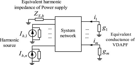
FIGURE 1. System harmonic equivalent circuit.
In Figure 1, the conductance to ground for each VDAPF which connected to parallel on the node is expressed by the harmonic conductance. The power branch of the large power grid side is equivalent to the harmonic impedance to ground. Taking the hth harmonic circuit as an example, ZS,h is the equivalent harmonic impedance of the power supply on the large grid side, and Ih,n is the hth harmonic current of the harmonic source n, and gm is the equivalent harmonic conductance of mth VDAPF, and im is the harmonic compensation current injected by mth VDAPF.
2.2 Harmonic Optimization Method on Long Time Scale
2.2.1 Global Optimization Objective Function
The data monitoring and collection system of distribution network generally collects data every 15 min, and the active and reactive power dispatching of the distribution network usually takes 15 min as the dispatching period (Xia et al., 2019; Zhao et al., 2019). Therefore, the long-time scale optimization takes 15 min as the time granularity. It considers the overall optimization of power quality at the nodes in the entire network, and it takes harmonic conductance values of VDAPF at distributed and parallel connected nodes as the optimization variables. The weight coefficient cn corresponding to different nodes is set to characterize the degree of requirements for the power quality.
This paper introduces the node sensitivity factor α, whose value reflects the sensitivity about voltage distortion of the load equipment which is connected to nodes. The larger the value of α, the higher requirement for distortion of the node. As shown in Eq. 1, the weight coefficient of the node is defined by the proportion of the sensitivity factor of the known nodes in all the nodes.
In the formula, αj is the load sensitivity factor of node j, and its value can be set and adjusted according to actual situation, and N is the total number of system nodes.
Considering the difference in the weight coefficients of different nodes, the objective function of long-term global optimization are set as the weighted summation of the harmonic voltage distortion rate of the nodes. The calculation formula is shown in Eq. 2.
In the formula, fTHD is the objective function of global optimization; cj is the weight coefficient of node j, whose magnitude can be obtained by Eq. 1; THDj represents the total voltage distortion rate of node j, which is calculated by Eq. 3.
In the formula, U1,j is the effective value of the fundamental wave’s voltage at node j; Uh,j is the effective value of the voltage of h-order harmonic at node j, which can be calculated by the h-order harmonic power flows.
2.2.2 Global Optimization Constraints
During the harmonic compensation process of VDAPF, the maximum compensation amount cannot exceed the rated capacity limit. That expressed as Eq. 4.
In the formula, SAPF,ci are the actual total harmonic compensation capacity of the ci VDAPF; S0APF,ci are the rated capacity of the ci VDAPF.
The compensation capacity SAPF,ci can be calculated by Eq. 5.
In the formula, Gh,ci are the values of hth harmonic conductance of VDAPF, and Uh,ci are the hth harmonic voltages of the VDAPF node. The particle swarm optimization (PSO) has fast solution speed and few parameters. The particle updates its speed and position according to Eq. 6.
In the formula, Vk+1i represents the particle velocity of particle i in the k+1 iteration; Xk+1i i represents the position of particle i in the k+1 iteration; Pkbesti and gkbesti respectively represent the particle i at individual optimal position and global optimal position at the k iteration; ω is the inertia weight; c1 and c2 are respectively the individual learning factor and the group learning factor; r1 and r2 are random values between [0, 1].
The inertia weight when the particle update velocity needs to be increased successively with the number of iterations, the inertia weight shown in Eq. 7 changes from the maximum to the minimum.
The steps to improve the PSO algorithm are:
1) Initializing the conductance value and the change rate of each harmonic conductance of VDAPF;
2) Comparing the objective function’s values of all conductance under different harmonics and getting the corresponding optimal conductance value;
3) Updating the conductance value and the change rate according to current inertia weight value;
4) Performing the next iteration calculation;
5) Setting the error threshold or the number of iterations as the iteration termination condition. If one of them is met, the iteration will be terminated and the final global optimal conductance value will be obtained; otherwise, return to step (4).
2.3 Multi-Time Scale Rolling Optimization
According literature (Zhang et al., 2017; Huang et al., 2019; Yan et al., 2019), the time granularity of the daily active and reactive power dispatching of the distribution network is generally maintained at the minute level, such as 1–5 min. Therefore, the short-time-scale prediction choose 5 min. The rolling optimization method is an optimization method which combined 5 min prediction and the long-time scale optimization. Its feature is to perform the rolling optimization of the local control operating characteristic parameters based on the short-term prediction of the harmonic current.
The model predictive control (MPC) method was used in short-time scale current prediction. Its characteristic is to solve the optimization model in a finite time domain according to the objective function and the constraints. In the vector of the obtained optimal solution, the first decision variable is taken as the optimal decision for on the current period. The optimization task of each sampling time is performed according to this cycle, and a new objective function is obtained according to the updated measurement information, and the solution is updated. Combining the control method and optimization objective of the VDAPF local controller of the zone, the difference between the actual voltage and the reference voltage of each node in the zone is controlled firstly. That is to make the difference between actual harmonic voltage and reference value of the harmonic voltage smallest in time domain. For the hth harmonic, the objective function J is shown as Eq. 8:
In the formula, Uhj is the actual hth harmonic voltage of node j, and Uh*j is the reference voltage of hth harmonic of node j.
The constraints during the solution process are shown in Eq. 9.
In the formula, Uhj max is the limit voltage of each harmonic.
Based on current state and system model, the rolling method cycle of a limited time domain, and updates the forecast information and operating status in the future scheduling cycle. Then it re-optimizes in the current rolling window, and executes results of scheduling decisions.
2.4 Parameters Setting
In order to verify the effectiveness of the harmonic distributed optimization method based on the combination of VDAPF global optimization and local control, IEEE 33-nodes distribution network system is taken as the example.
According literature (Zhou et al., 2015), the electrical load connected to each node contains a variety of sensitive loads, and different equipment is divided into four levels by the sensitivity of equipment voltage sags. The weight coefficient cj of each observation node is set to represent the degree of voltage distortion, and is reflected in the proportion of voltage distortion in the total objective function in the optimization process. For the nodes which connected to electric sensitive load, the sensitivity factors of nodes 4, 23, and 28 is setting to 10, 9, and 7, and the sensitivity factors of other nodes is setting to 1. The weight coefficient of each node is shown in Table 1.
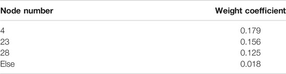
TABLE 1. Weight coefficient of each node.
Long-term scale PSO parameters: the maximum inertia weight ωmax is 1.4; the minimum inertia weight ωmin is 0.4; the initial value of the learning factor is 2; the particle swarm size is 400, and the maximum number of iterations is 150.
3 Results and Discussion
3.1 Results of Two Scenario
Since the affection of harmonic are different, this paper considers two different harmonic injection scenarios which injected 10 and 20%. The global optimization results of the equivalent conductance of each harmonic of the VDAPF at each control node in Scenario 1 and Scenario 2 were shown in Tables 2, 3.
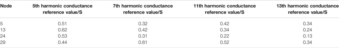
TABLE 2. Global optimization results of VDAPF harmonic equivalent conductance under scenario 1.
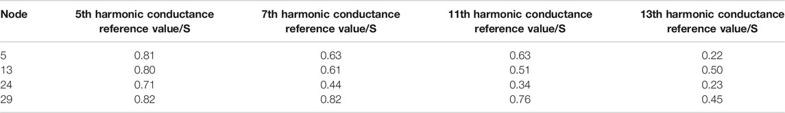
TABLE 3. Global optimization results of VDAPF harmonic equivalent conductance under scenario 2.
In scenario 1, the harmonic conductance values of VDAPF can be seen from Table 2. The conductance value of higher-order harmonic is smaller than the lower-order. For example, the 13th and 11th harmonic conductance values of the control nodes 13 and 24 are smaller than the 5th and 7th harmonic conductance values; the 13th harmonic conductance value of the control node 29 is smaller than the harmonic conductance values of other control nodes; and the conductance value of the 13th harmonic of node 5 is small. Because the low-order harmonics injected into the network by the harmonic source such as the 5th and 7th harmonics have larger amplitudes, while the content of higher-order harmonics is less. Since the equivalent harmonic conductance of VDAPF characterizes the intensity of harmonic control, the content of low-order harmonics in the network is relatively high, and the corresponding harmonic conductance value is relatively large, so greater control intensity is required for low-order harmonics.
In Table 3, the harmonic conductance value of VDAPF also follows the same law, that is the conductance value of higher-order harmonic is smaller than the lower-order. Because the overall harmonic current injection of scenario 2 is larger than that in scenario 1, and the resulting harmonic pollution is also more serious. At the same time, it also satisfies that the injection amplitude of high-order harmonic current is smaller than that of low-order harmonic current injection. Similarly, the equivalent harmonic conductance of VDAPF characterizes its treatment strength. Therefore, under the same network parameters, more serious harmonic pollution requires more treatment to smooth the harmonic current injection.
Comparing the harmonic conductance optimization results of scenario 1 and scenario 2, it can be concluded that the harmonic conductance value of the VDAPF in scenario 1 is generally smaller than the value of scenario 2. Because the harmonic pollution of scenario 2 are more serious than scenario 1, and stronger treatment is required, and the harmonic conductance value represents the intensity of VDAPF’s treatment of harmonics. The greater the harmonic conductance, the greater the required intensity of harmonic control. Therefore, under the requirements of the same harmonic voltage limit, the VDAPF needs to output more control amounts under the scenario of more serious harmonic pollution.
3.2 Comparison of Multi-Time Scale Rolling Optimization and Global Optimization Results
Option 1: Distributed global optimization method used in this paper based on the voltage detection type APF grid-side.
Option 2: Decentralized local harmonic control method based on current detection type APF.
The results of voltage distortion rate of each node before and after mitigation in two scenarios are shown as Figures 2, 3.
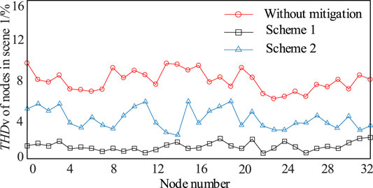
FIGURE 2. Total voltage distortion rate of each node before and after mitigation under scenario 1.
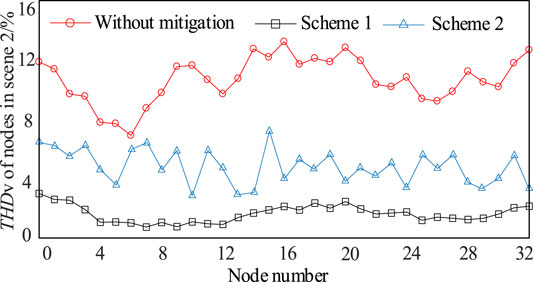
FIGURE 3. Total voltage distortion rate of each node before and after mitigation under scenario 2.
The voltage distortion of each node is compared, and the comparison results under scenario 1 and scenario 2 are shown in Figures 4, 5, respectively.
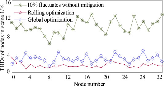
FIGURE 4. Comparison results of operating point mitigation between rolling optimization and global optimization under scenario 1.
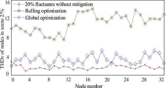
FIGURE 5. Comparison results of operating point mitigation between rolling optimization and global optimization under scenario 2.
For Scenario 1, when a 10% fluctuation occurs to the harmonic current injection, the harmonic voltage distortion of each node is aggravated. If the solution to the global optimization result is still used to manage, it can be seen in Figure 4 that there are nodes with unqualified voltage distortion in each partition, such as node 3, node 10, node 22, and node 28. This verifies that the global optimization results are only feasible for long-term but the actual harmonic current injection fluctuates in real time. The fluctuation range after multi-time scale rolling optimization are smaller than global optimization method. The multi-time scale optimization method is more efficient than Global optimization method.
It can be seen from Figures 3–5 that for scenario 2, the harmonic current injected by the harmonic source load has a 20% fluctuation, and the harmonic voltage distortion of each node is aggravated also, and global optimization is adopted. As a result of the solution, the number of nodes with unqualified voltage distortions in each partition is significantly increased compared with scenario 1, such as node 10, node 19, and node 30, which are more serious. It is also verified that the global optimization results are only for the long-term, and the actual harmonic current is injected into real-time fluctuations. The global optimization results need to be combined with the short-time-scale rolling optimization to ensure the harmonics of all nodes in each region. The multi-time scale optimization method is more efficient than Global optimization method.
4 Conclusion
This paper proposes a multi-time-scale harmonic optimization method based on the long-term scale global optimization of the distributed VDAPF and the short-time scale rolling optimization of local control. The long-term scale global optimization aims at the overall optimization of the voltage distortion at all nodes of the distribution network. It constructs a global optimization objective function and constraint conditions, and using intelligent optimization algorithms to solve the global optimization model. The operating characteristic parameters of VDAPF are optimized on a short time scale base on MPC, and the feedback correction is brought in to correct the predict deviation caused by mitigation error to make the harmonic voltage of every node always maintained at a qualified level. Through the multi-time scale optimization, the harmonic control is continuously revised, and optimized entire nodes of the distribution network. It provides a grid-side solution for the power electronic distribution network to optimize the harmonic voltage of the entire network nodes.
The multi-time-scale optimize method can solve the large fluctuation problem of harmonic voltage in global optimization method, but the short-time-scale prediction need more memory and calculation. It needs communication on time with control computer. In addition, this method can efficiently mitigate the 13th and lower harmonic, but the effects about higher harmonic are not verified in this paper, and that would be studied in after work.
Data Availability Statement
The original contributions presented in the study are included in the article/Supplementary Material, further inquiries can be directed to the corresponding author.
Author Contributions
LS, Work concept or data collection; LX, Draft the paper and make revisions to the paper; LL, Model design and simulation; QJ, make revisions to the paper.
Funding
This work was supported in part by Open Fund Project of Key Laboratory of Power Conversion, Transmission and Control in Inner Mongolia Autonomous Region (No. IMEECTC2020002).
Conflict of Interest
The authors declare that the research was conducted in the absence of any commercial or financial relationships that could be construed as a potential conflict of interest.
Publisher’s Note
All claims expressed in this article are solely those of the authors and do not necessarily represent those of their affiliated organizations, or those of the publisher, the editors and the reviewers. Any product that may be evaluated in this article, or claim that may be made by its manufacturer, is not guaranteed or endorsed by the publisher.
References
Artale, G., Caravello, G., Cataliotti, A., Cosentino, V., Cara, D. D., Guaiana, S., et al. (2021). Measurement of Simplified Single- and Three-phase Parameters for Harmonic Emission Assessment Based on IEEE 1459-2010. IEEE Trans. Instrum. Meas. 70 (99), 1–10. doi:10.1109/tim.2020.3037949
Chen, X., Dai, K., Xu, C., Peng, L., and Zhang, Y. (2017). Harmonic Compensation and Resonance Damping for SAPF with Selective Closed‐loop Regulation of Terminal Voltage. IET Power Elect. 10 (6), 619–629. doi:10.1049/iet-pel.2016.0344
Ebrahimzadeh, E., Blaabjerg, F., Wang, X., and Bak, C. L. (2019). Optimum Design of Power Converter Current Controllers in Large-Scale Power Electronics Based Power Systems. IEEE Trans. Ind. Applicat. 55 (3), 2792–2799. doi:10.1109/tia.2018.2886190
Huang, W., Liu, S., and Yi, Y. (2019). Multi-Time-Scale Slack Optimal Control in Distribution Network Based on Voltage Optimization for point of Common Coupling of PV[J]. Automation Electric Power Syst. 43 (3), 92–100. doi:10.7500/AEPS20180328003
Lee, T.-L., Cheng, P.-T., Akagi, H., and Fujita, H. (2008). A Dynamic Tuning Method for Distributed Active Filter Systems. IEEE Trans. Ind. Applicat. 44 (2), 612–623. doi:10.1109/tia.2008.916596
Munir, H. M., Zou, J., Xie, C., and Li, K. (2019). Direct Harmonic Voltage Control Strategy of Shunt Active Power Filters Suitable for Microgrid Applications [J]. J. Power Elect. 19 (1), 265–277. doi:10.6113/JPE.2019.19.1.265
Munir, M. S., Tian, H., and Li, Y. W. (2020). Residential Distribution System Harmonic Compensation Using Priority Driven Droop Controller. Cpss Tpea 5, 213–223. doi:10.24295/CPSSTPEA.2020.00018
Tian, S., Jia, Q., Xue, S., Yu, H., Qu, Z., and Gu, T. (2020). Collaborative Optimization Allocation of VDAPFs and SVGs for Simultaneous Mitigation of Voltage Harmonic and Deviation in Distribution Networks. Int. J. Electr. Power Energ. Syst. 120, 106034. doi:10.1016/j.ijepes.2020.106034
Wang, X., Blaabjerg, F., and Blaabjerg, F. (2019). Harmonic Stability in Power Electronic-Based Power Systems: Concept, Modeling, and Analysis. IEEE Trans. Smart Grid 10 (3), 2858–2870. doi:10.1109/tsg.2018.2812712
Xia, P., Liu, W., and Zhu, D. (2019). Multi-Time Scale Optimal Control Method of Reactive Power and Voltage Based on Model Predictive Control[J]. Electric Power Automation Equipment 39 (3), 64–70. doi:10.16081/j.issn.1006-6047.2019.03.010
Xie, X., Sun, Y., Wang, Q., Li, Y., Zhang, Y., and Zhang, L. (2021). A Piecewise Probabilistic Harmonic Model of Aggregate Residential Loads. IEEE Trans. Power Deliv. 36 (2), 841–852. doi:10.1109/TPWRD.2020.2995081
Yan, X., Xu, Y., Li, R., and Jin, Y. (2019). Multi-Time Scale Reactive Power Optimization of Distribution Grid Based on Model Predictive Control and Including RDG Regulation[J]. Trans. China Electrotechnical Soc. 34 (10), 2022–2037. doi:10.19595/j.cnki.1000-6753.tces.181605
Yang, W., Jing, Y., Sun, Y., and Xu, W. (2017). Characteristics of Harmonic Distortions in Residential Distribution Systems[J]. IEEE Trans. Power Deliv. 32 (3), 1495–1504. doi:10.1109/TPWRD.2016.2606431
Zhang, B., Tang, W., and Cong, P. (2017). Multi-Time Scale Optimal Control in Hybrid AC/DC Distribution Networks Based on SOP and VSC[J]. Adv. Tech. Electr. Eng. Energ. 36 (9), 11–19.
Zhao, B., Ni, C., and Li, Z. (2019). Multi-Time Scale Optimal Scheduling of Electricity-Gas Hybrid System Based on Adaptive Step Size ADMM[J]. Electric Power Automation Equipment 39 (8), 294–299.
Keywords: multi-time scale predictive, VDAPF, harmonic mitigation, MPC, high proportion clean energy
Citation: Suo L, Lin L, Xing L and Jia Q (2022) Multi-Time Scale Harmonic Mitigation for High Proportion Electronic Grid. Front. Energy Res. 9:801197. doi: 10.3389/fenrg.2021.801197
Received: 25 October 2021; Accepted: 07 December 2021;
Published: 27 January 2022.
Edited by:
Yuefang Du, University of Electronic Science and Technology of China, ChinaCopyright © 2022 Suo, Lin, Xing and Jia. This is an open-access article distributed under the terms of the Creative Commons Attribution License (CC BY). The use, distribution or reproduction in other forums is permitted, provided the original author(s) and the copyright owner(s) are credited and that the original publication in this journal is cited, in accordance with accepted academic practice. No use, distribution or reproduction is permitted which does not comply with these terms.
*Correspondence: Licheng Xing, bGljaGVuZ3pob25nYmVpQDE2My5jb20=