 Peter Alenoghena Aigba1*
 Ikuobase Emovon1
 Olusegun David Samuel1,2*
 Christopher Chintua Enweremadu2Thabet Abdeljawad3,4*Qasem M. Al-Mdallal5
 Asif Afzal6,7*
- 1Department of Mechanical Engineering, Federal University of Petroleum Resources, Effurun, Nigeria
- 2Department of Mechanical Engineering, University of South Africa, Florida, South Africa
- 3Department of Mathematics and Sciences, Prince Sultan University, Riyadh, Saudi Arabia
- 4Department of Medical Research, China Medical University, Taichung, Taiwan
- 5Department of Mathematical Sciences, United Arab Emirates University, Al Ain, UAE
- 6Department of Mechanical Engineering, P. A. College of Engineering (Affiliated to Visvesvaraya Technological University, Belagavi), Mangaluru, India
- 7Department of Mechanical Engineering, School of Technology, Glocal University, Saharanpur, India
Natural gas processing, as one of the major energy sources, has become a focal point in boosting the energy value chain by processing high commercial value products such as natural gas liquids (NGL) and electricity generation. Natural gas processing has also amplified its usefulness to human well-being and global prosperity in different ways. However, the spate of gas flaring is a global phenomenon, despite advances in waste gas management technology. This research describes a unique integrated plant that recovers NGL and produces electricity via waste gas for the energy conversion process. Exergetic analysis has been offered to identify the causes of irreversibilities in the plant. Simulation models were built using the AspenOne HYSYS V10 and Aspen Plus V10 software to conceptualize the plant. The recovery of 60 kBD NGL and 2.55 kg mol/s of 97% lean methane gas (95% purity) as the residue was achieved from 320 MMSCFD of waste gas processing. The residue methane gas is combusted in a combustion chamber to recover hot gas in a heat recovery steam generator (HRSG) for steam generation and production of 646 MW of electricity. Analysis revealed that the heat exchangers collectively accounted for about 78% exergy destruction in the NGL recovery plant, while the 3 and 1.54%, respectively, of exergy is destroyed and lost in the demethanizer. The steam power plant showed similar irreversibilities with the boiler exchanger accounting for up to 88% exergy destruction. About 1.4% of exergy is lost as flue gas to the environment. At optimization, overall exergy efficiency reached 77.5 and 80.6% in the NGL recovery and steam power plant, respectively. Thus, this integrated plant model has not only demonstrated a marked improvement to similar models but is also a lucrative alternative to waste flare gas management. It is also proven to be a “flare-capture” alternative model for fossil fuels-related emission reduction and optimization tool for waste gas to energy.
1 Introduction
1.1 Background and Literature Reviews
Natural gas is produced when separated from crude oil production (Figure 1). This produced gas is disposed of or destroyed due to a lack of infrastructure to process it and mitigate emissions releases (Emam, 2015). Gas flaring has been patronized from the inception of oil and gas production to relieve gas from eruptive wells or burn gas during refining (Mourad et al., 2009). This gas flaring process is largely responsible for energy waste and greenhouse gas (GHG) releases, as seen in many refineries today (Ismail and Umukoro, 2012; Abam et al., 2020).
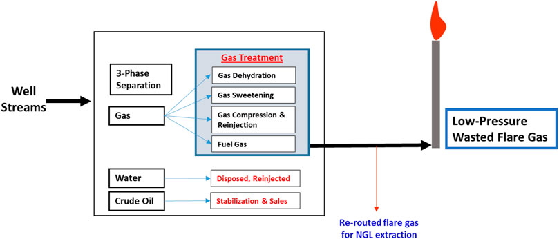
FIGURE 1. Production process overview.
Gas flaring today is indeed partly due to the convenience of minimizing financial resources for infrastructural installations or the lack of technological acquisition required to process this gas. It is on record that gas flare from fossil fuels releases 45.8 billion kilowatts of heat into the atmosphere daily, thus leading to raised temperatures and inhabitable large areas (Isichei and Sanford, 1976). Thus, business competency is required to manage wasted flare gas and achieve full economic exploitation. Carbon dioxide from fossil fuels contributes about 75% of the anthropogenic emissions (Anon, 2001), which is classified as the main source of GHG and the consequential global warming and climate change potential. These conditions have harmful effects on the global population growth, living standards, human health, and entire ecosystems (Tolulope, 2004; Uwem and Akpan, 2017). GHG emissions reduction is a top priority for the world health organization (WHO), the world bank, and other relevant government and non-governmental agencies. The U.S. national oceanic and atmospheric administration (NOAA), in partnership with the world bank, estimated flared gas volume in 2015 to 147 billion cubic meters (BCM) (Zubin, 2016). This is an enormous quantity of wastes of a natural resource that could generate over 750 billion kWh of electricity, which is more than enough to power the African continent (Zubin, 2016). The Kyoto protocol ratification and the environmental impact of flare gas have continued to increase awareness that flaring may not be allowed sooner (Malumfashi, 2007). This alliance will effect changes in the oil and gas production practices and processing for which several research works have been done, including Mourad et al. (2009) whose study on crude stabilization via multistage separation techniques recovered flared gas and Rahimpour et al. (2012) who recovered flare gas of the Farashband gas processing plant. However, Zadakbar et al. (2008) presented the economic and environmental values of reducing, recovering, and reutilizing flare gases from gas refineries in Iran.
The development of a flare gas recovery (FGR) system (Bhran et al., 2016), which can also be used to reduce thermal radiation, noise, and pollutants emissions from gas flaring (API, 1977), is one of the best solutions to gas flaring reduction, yet. Utilizing waste gas is an investment rather than a burden in many ways because the gas is converted to power or fractionated solely for economic gains (Abam et al., 2020). Rahimpour and Alizadeh-Hesari (2009) examined the Iran Asalooye refinery and proposed wasted gas recovery methods, which included power generation via gas turbines, gas-to-liquid (GTL) production, gas compression, injection, and pressure maintenance. Such methodologies play an important role in bringing wasted gas to cash (Landoli and Kjelstrup, 2007).
Natural gas liquids (NGLs) production is a useful byproduct of waste gas reutilization and processing. NGL can be described simply as liquids recovery from natural gas such as ethane and heavier hydrocarbon products. NGL recovery pertains to the refrigeration (mixed and cascade) process (GPSA, 1998). Ethane, propane, butanes, and natural gasoline are the most valuable components of natural gas in terms of their thermal value (Ghorbani et al., 2017). Hence, for its recovery, numerous separation structures, extraction processes, such as the Joule–Thomson (JT) expansion, refrigeration via refrigerants in a chiller, and turbo-expander have been proposed (Manning and Thompson, 1991). Each of these recovery process have their pros and cons depending on operator need, which determines the process footprints. Thus, Vatani et al. (2013) recommended an integrated structure for simultaneous NGL production that recovered 93% ethane using the HYSYS–MATLAB simulation program based on the propane mixed refrigeration (C3MR) cycle. Khan et al. (2014) presented a new optimization algorithm for the integrated refrigeration cycle for simultaneous NGL and liquefied natural gas (LNG) production similar to the Linde Company model (Linde natural gas plants, 2005). Uwitonze et al. (2016) presented three mixed refrigerant dual refrigeration cycle structures in the ultra-cold natural gas integrated processes (NGL, LNG), and Ghorbani et al. (2017) investigated an integrated structure that removes nitrogen from natural gas and produces LNG and NGL simultaneously via a refrigeration cycle. The study reached an exergy efficiency of 62.82% and a specific rate of power consumption of 0.32 kWh/kg LNG. The NGL processes are typically modelled and simulated to obtain detailed thermodynamic information and Mehrpooya et al. (2006) examined exergy analysis for NGL recovery in refrigeration cycle using simulation and concluded that exergetic efficiencies ranked lowest in the air cooler(s) and chillers among the components of the refrigeration cycle.
The heat from waste flare gas is usually at low temperatures, thus making its conversion into other forms of hydrocarbons and electrical energy difficult. As a result, research on waste energy conversion to other forms of usable end-products is continuously done (Ghannadzadeh et al., 2012). Marin et al. (2014) examined energy and exergy concepts via ORC powered by solar (low-grade heat source) to generate working fluid heat energy and (Valencia et al., 2019) investigated the energy and exergy analysis of triple ORC–waste heat recovery (WHR) assembly using thermal oil circuit to improved overall power conversion efficiency by 11.58% as waste heat driven-ORC. The organic Rankine cycle (ORC) and heat recovery processes are auspicious technologies for medium and low-grade waste heat energy conversion into mechanical power and electricity (Patel et al., 2016). Other research works on exergetic analysis include the use of simulators to generate expressions for exergy balance, heat and work streams, to automate exergy analysis, (Abdollahi-Demneh et al., 2011; Querol et al., 2011; Ghannadzadeh et al., 2012). The first law of thermodynamics can be conveniently used to analyze the energy quantity and not the quality of waste gas when estimating energy utilization in a waste gas to the energy system. This shortfall in the first law gives credence to the essence of exergy in the second law. The concept of exergy helps to estimate the potential to do useful work (energy quality) at a specific state (Cengel and Boles, 2006; Saidur et al., 2010) as defined by the second thermodynamic law (Habib et al., 1999; Sciubba and Wall, 2004). Therefore, exergy, unlike energy, can be destroyed. Therefore, it is not conserved in a non-reversible heat transfer or chemical reaction process (Brodyansky et al., 1994). Exergy has been applied widely to the evaluation and analysis of isolated thermal systems (Jokandan et al., 2015), components of a system (Rakopoulos and Giakoumis, 2006), and energy utilization in countries such as the United States, Canada, Japan, Sweden, Italy, United Kingdom, Malaysia, Norway, and China, for energy resource management (Saidur et al., 2010; Eisenmenger et al., 2017; Calvo et al., 2018; Hernandez et al., 2018).
Several research works on thermal power plants around the globe have investigated the effect of exergy. Rosen (2001) adopted exergy analysis to evaluate the overall performance of coal and nuclear power stations. Amir (2012) assessed a steam power plant boiler using the energy and exergy analysis method and concluded that a fractional decrease in combustion excess air was responsible for a proportional increase in the energy and exergy efficiency of the plant and that additional fractional increase in the mentioned efficiencies is achieved by a decrease in temperature from 137°C to 90°C. Habib et al. (1999) studied the steam cycle of a power plant and determined the exergy and exergy costs balance for components and the system when they optimized a double reheat in the thermal power plants. Kwak et al. (2003) applied mass and energy balance on components when analyzing a 500 MW combined cycle plant. The developed computer program was able to evaluate the thermodynamic performance and sensitivity to changes in both processes and the design variables of the components. Other research works on exergetic analysis of thermal plants include the evaluation of components’ exergetic losses in a dual-stage vapor compression cycle (Ouadha et al., 2005). Furthermore, Önder (2014) analyzed exergy destruction in the steel industry using actual plant data. Ameri et al. (2008) scrutinized a 420 MW combined cycle power plant (CCPP) in Neka, Iran, using the exergetic methodology to evaluate the major components of the plant and identified the combustion chamber, HRSG, duct burner, and gas turbine as the main sources of irreversibility as they contribute 83% of the total exergy destruction in the plant. Ahmadi and Toghraie (2016) investigated the energy and exergy analysis of a 200 MW Montazeri steam power plant of Iran using a mass, energy, and exergy balance approach. They found that 69.8% of the total energy loss was rejected from the condenser, and the boiler destroyed 85.66% of the total plant exergy. Patel and Agrawal (2019) investigated the effect of various process parameters on plant efficiencies to prioritize them for possible improvement in energy input utilization when they examined a 250 MW coal-fired thermal power plant using a flow sheet computer program Cycle Tempo 5. Shamet et al. (2021) presented the energy and exergy analysis of the Garri 4 power plant in Sudan to identify the main sources of irreversibilities in the plant. They confirmed that the condenser rejected 67% as the main source of energy rejection while the boiler contributed the largest exergy destruction of 84.36%. The loss of exergy generally provides an applicable quantitative measure of an inefficient process. Kotas (1995) analyzed the total irreversibility distribution of a multi-component plant and identified the highest contributors to the overall plant inefficiency. Shin et al. (2015) further used thermodynamic applications and optimization analysis to provide design methodology for improving energy-efficient systems (Yoon et al., 2017).
Moran (1982) with Pilankar and Kale (2016) showed that energy and exergy analyses, which are a major component of the laws (first and second) of thermodynamics, can be used as a tool to determine the components inefficiency sources and analyze thermodynamic losses in a chemical and fertilizer industry. The results indicated that the combustion chamber contributed over 50% of the total exergy destruction in the overall cycle. Khaliq and Kaushik (2004) adopted an exergetic tool to investigate reheat in a combined Brayton/Rankine power cycle use. Exergy has also been analyzed in a small biomass-fed ORC power plant consisting of a combustion burner that utilized biomass as fuel to produce power (Nur and Sunoto, 2018). They concluded that the combustor and the pump contribute the most and the least exergy destruction in the components. Some researchers (Jouhara et al., 2018; Brückner et al., 2015; Shengjun et al., 2011) also focused on the analysis and utilization of waste heat in power generation. Suryo et al. (2019) emphasized that exergy analysis can be used to locate and determine causes and sources of thermodynamic losses toward improving the performance of the existing systems and constructing new energy-efficient systems.
1.2 Motivation and Novelty of the Study
From exhaustive reviews, many research studies abound on waste gas utilization in literature, as highlighted. However, most of their emphasis is focused on the use of waste gas for power generation and as fuel gas for machinery or fractionation for NGL/LNG production. Reports on waste gas to energy utilization and the conversion of methane gas residue to generate power are absent in the published journal and the integration of an NGL recovery plant and steam power generation plant. Therefore, this study seeks novelty in its ability to integrate both plants. This plant system will not only minimize the potential for greenhouse gas emissions but also serve as a profitable alternative to gas flaring. Energy and exergy analysis is applied in this study as a thermodynamic tool that will help determine exergy loss which may be associated with the integrated NGL recovery and the steam power plants, their optimal designs, and operations (Salas et al., 2017). AspenOne HYSYS V10 and Aspen Plus V10 will be used to model the plants and identify areas of thermodynamic irreversibilities, including causes, location, and magnitude, and determine areas of improvements to minimize the system energy requirement and enhance performance.
2 Process Description
Figure 1 depicts the conventional process of oil and gas separation in a processing plant. Unused gas after the gas treatment process is burnt at the flare as wasted gas. In this study, this low-pressure waste gas is being re-routed from the flare stack into the integrated NGL recovery and the steam power generation plants. The schematic shown in Figure 2 illustrates the process flow schematics of the proposed integrated plant. It is shown that the re-routed low-pressure waste flare (rich) gas is channeled into a gas gathering vessel, where it is produced into a multistage booster screw compressor with interstage coolers (heat exchangers). The intercoolers and the chillers will drop the feed stream temperature before the stream is splintered into the expander, where the gas is expanded to further lower the temperature and pressure of the rich gas stream into a demethanizer column. Cold methane is produced from the column top and NGL from the column bottom. The side reboiler is set at the lower part of the demethanizer to achieve optimum energy integration and recover the cold energy in the column. The cold-produced lean methane gas is routed and warmed through the heat exchange shell in a subcooled process into a gas combustor in the steam power plant. The hot gas produced in the combustor passes through the heat recovery steam generator (HRSG) to produce steam at 275.6°C into the steam turbine blade in a Rankine cycle-related process that produces electricity.
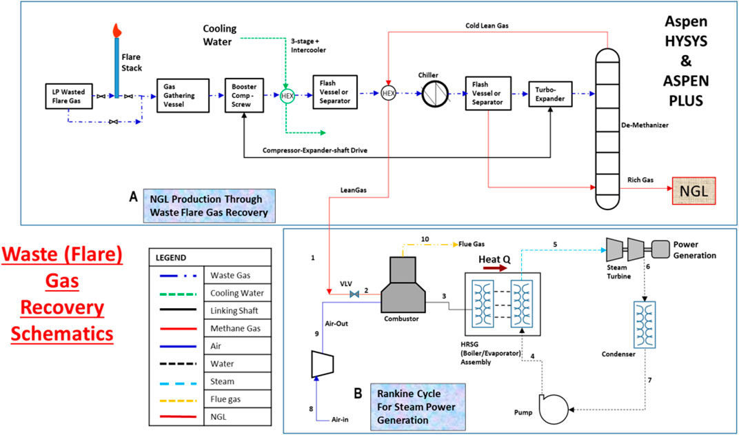
FIGURE 2. Process schematics for the integrated waste gas to energy for [A], NGL recovery plant and [B] steam power generation plant.
2.1 Methodology—Process Simulation
Aspen HYSYS V10 and Aspen Plus V10 are used to model and simulate the integrated plant processes by employing the Peng–Robinson equation of state (EOS) (Figure 3) and IAPWS-97 (Figure 4) as the fluid package (Aspen Tech, 2013), respectively. With these simulators, the thermodynamics properties for the process using a waste gas composition shown in Table 1 were obtained. In this study, energy and exergy are utilized for evaluating the main components of the system. The compressor (Comp-103) and expander (Exp-101) are physically linked with a shaft as a turbo-expander. In Aspen HYSYS, the link installed between the compressors and expanders indicate that the speed of each linked unit is the same and the cumulative sum of the duties of each unit and the total power loss equals zero. The NGL recovery processes in the study used turbo-expander, which is also often used in both the oil and gas industry (Manning and Thompson, 1991; Shin et al., 2015; Tahmasebi et al., 2015; Ansarinasab et al., 2016) and conventional engineering processes, namely, the gas subcooled process, the split vapor recycle, and the cold residue processes (see Figure 2).
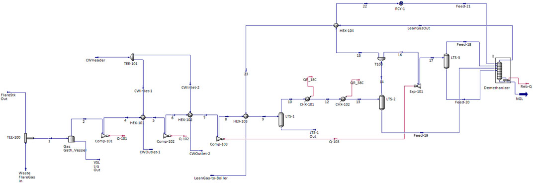
FIGURE 3. HYSYS modeled natural gas liquefaction recovery plant process.
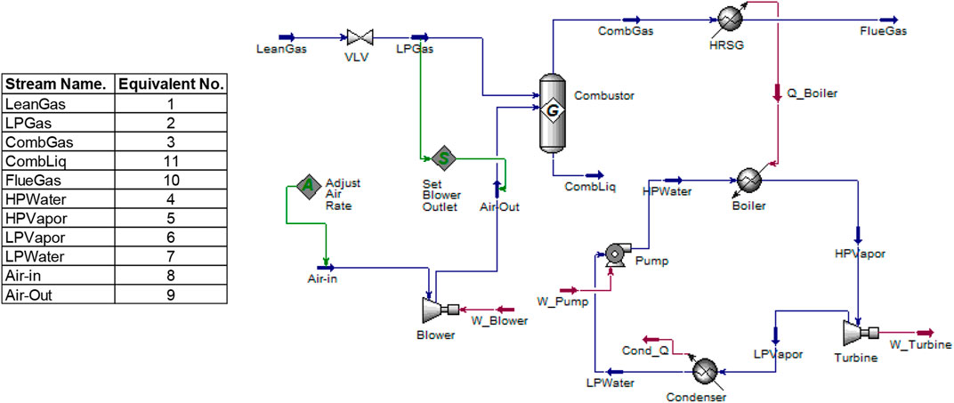
FIGURE 4. HYSYS modeled steam power plant process.
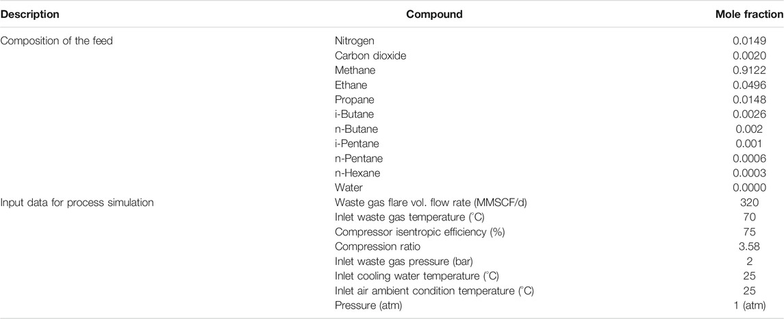
TABLE 1. Composition of the feed.
The subcooled process of gas involves passing compressed feed gas at 91 bar in a precooled process through HEX-101, HEX-102, and HEX-103 and the chillers (CHX-101 and CHX-102) and then expansion in the turbo-expander cryogenically into the column from where the top product streams provide cooling. The vapor stream from the flash drum (LTS-2) is split into two streams in a subcooled process which helps enhance the high recovery of the NGL (C2+) product (Mehrpooya et al., 2006). The first stream is cooled in the HEX-104 with a stream from the column top product. The stream is expanded and recycled as a reflux stream into the top of the demethanizer column as well, Figure 3. The second stream is fed through the turbo-expander to deliver NGL demethanizer column bottom. The small liquid stream from the flash drum (LTS-3) also fed into the bottom of the column. The split vapor recycles and the cold residue reflux processes are constituents of the subcooled process, which helps increase methane recovery. After the expansion processes, the methane-rich cold stream (lean gas) from the demethanizer column top is cycled through the two process-process HEX-104 and HEX-103 into the combustor in a process that allows the pure methane gas to be maintained at equal pressure with compressed air from the blower.
In the steam power plant model in Figure 4, the pressurized air from the blower is stoichiometrically combined with fuel to release high-temperature hot gas, which is recovered through the HRSG-evaporator (boiler exchanger) assembly to produce hot steam into the steam turbine blade. Low temperature and pressure steam is released from the steam turbine into the condenser at atmospheric temperature. Energy is seen to be also released to the surroundings as flue gas during the combustor process. However, this cycle resembles an ORC model concept and one in which heat sources and steam are selected as the working fluids.
The data inputted into the simulation is shown in Table 2. However, the Aspen HYSYS process parameter can be adjusted in such a way that the user sets the target variable value and specifies an adjusted variable used to reach the target value, as seen in Figure 3.
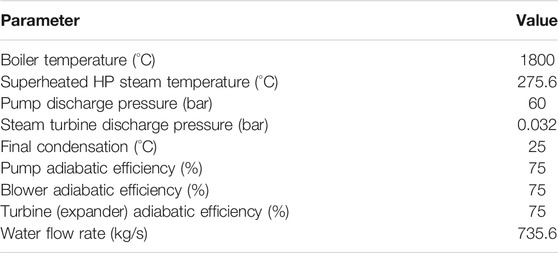
TABLE 2. Simulation input data of the utility system.
2.2. Demethanizer Column Simulation
The demethanizer column in Appendix B (Supplementary Appendix B Figure S1) is used to separate methane gas at the column top and other heavier hydrocarbons at the column bottom. This reboiler-only column does not have a condenser at the top and therefore does not have cold reflux from the column top. The simulated 30-tray demethanizer column is set at 1% methane recovery to ensure that most ethane and heavier hydrocarbons are produced at the column bottom. The lower demethanizer pressure and separation pressure enhance the volatility difference and pressure energy utilized between
3 Thermodynamic System Models: Energy and Exergy Analysis
The integrated plant processes are thermodynamically modeled, based on the following major assumptions:
3.1 Air, Fuel Combustion, and Steam System Assumptions
A simple natural gas burner/boiler was created with the following process conditions:
• Natural gas (100% methane) is available as a product of NGL recovery from the demethanizer column at a delivery pressure, 5.7 bars, and 130°C.
• Air is available at 25°C, and it is characterized and modeled as 21% oxygen and 79% nitrogen molar mixture and dry (i.e., no water). Air is added up to 20% of excess oxygen to optimize and achieve complete gas combustion.
• The pressure drops across the combustor, the HRSG is maintained at 0.3 bars, and the flue gas is emitted at 120°C to prevent any liquid dropout and subsequent corrosion problems.
• No extra pressure drops through heat exchangers (HEXs) or piping or between components.
• The feed temperature, pressure, and flow rate are 70°C, 2 bars, and 320 MMSCF/d, respectively, and
• Water at 25°C converted to steam at 275.6°C, no superheat.
• Reference environment: temperature,
• Dead state: enthalpy,
• The ambient model reference for air in this analysis is generated by HYSYS.
3.2 Integrated Plant Streams Properties
In the NGL recovery sections: Peng–Robinson EOS is chosen for the following reasons:
• The mixture is strongly non-ideal and non-liquid, with no hydrogen and hydrogen sulfite, as it is made of hydrocarbons.
• The lean residue gas from the column top is modeled as a mixture of light hydrocarbons such as methane, ethane, and propane.
• The cycle is a steady flow and steady state.
• Compressors and expanders isentropic efficiencies operate at 75% (Yoon et al., 2013).
• The combustion process occurs near atmospheric conditions.
Other properties include the following:
•
In the steam power process sections: IAPWS-97 for the thermodynamics properties of water is chosen for the following reasons:
• The cycle is a steady flow and steady state.
• The pressure-reducing valve is used as an adiabatic process.
• Process in pumps, compressors, or blower and the steam turbine is isentropic.
• The heat carrier of exhaust or flue gas is non-corrosive and non-condensable.
• Steam is modeled as pure water.
• The steam turbine and pump will operate at an ideal reversible condition.
• Other products of combustion gas considered in the model include
4 Mass, Energy, and Exergy Balance of the Integrated Plant Process
This section evaluates the general expressions of mass, energy, and exergy balances of the plant at a control volume (CV). Thus, any possible energy changes across the boundary are assumed as negligible.
4.1 Mass Balance of the Integrated Process Plant
Mass balance (continuity) equation:
Appendix A (Supplementary Appendix A Tables S1 and Supplementary Appendix A Tables S2) shows mass balance equations and calculations for the stream mass inflow and outflow, respectively. The process imbalance and relative imbalance (% mass error) are also determined as shown in Supplementary Appendix A Equations A1, A2. From the result, that mass inflow is equal to the mass outflow (% imbalance is zero). In order words, the material flow in the streams is conserved and coherent with the plant design.
4.2 Energy Analysis of the Integrated Plant
Oil and gas industry players often advance their own indicators to assess energy performance processing (Nguyen et al., 2014). This indicator includes the following:
• The energy efficiency η, the ratio of the inlet to outlet in the plant.
• The energy intensity ih, the ratio of the used energy to exported energy.
• The energy waste ωh, the ratio of flared gases energy to total energy generated.
• The specific power consumption w, the power consumed per unit of oil and gas equivalent relative to the standard volume basis,
• The specific CO2 emissions.
Generally, these indicators are often used to identify possible energy imbalance and leaks in the system (Nguyen et al., 2014). Aspen HYSYS has been used to derive the energy balance, imbalance, and relative imbalance (% error) of the streams using the relevant Supplementary Appendix A Equations A3, A4 in appendix A. From the overall energy analysis perspective, energy is induced by the mass flow rate, the useful work output, and the energy released to the environment. Therefore, at a steady-state control volume, the energy balance can be expressed by Eqs 2–4:
Applying the thermodynamics first law control volume (CV) can be expressed as Eq. 4:
This law will be largely applied in determining energy balance and efficiency evaluations in this study, more clearly defined in Appendix A (Supplementary Appendix A Tables S1). For example, energy recovered in the HRSG conforms to Eq. 4 as shown on Eq. 5 and the system thermal efficiency as Eq. 6.
The thermal efficiency calculation obtained from Eq. 6 undermined the boiler combustion process contribution and its constituent heat losses under load. More accurately, the plant energy efficiency calculation should consider the combustion process. Thus, the plant energy efficiency is better defined as the ratio of produced work (net) to the fuel energy is given as Eq. 7:
4.2.1 Energy Duty Requirement in the Integrated Plant
From the HYSYS model, the energies demand of each of the components is shown in Appendix B (Supplementary Appendix B Figures S2, S3, S4) for the NGL recovery and the steam power plants. In the NGL recovery plant, the multistage booster compressors do enormous work on the natural gas stream to get the gas to the required pressure, where the rich gas (containing heavy carbon elements) component of the stream is stripped off in the expander. To conserve the expander-produced work, it is linked with a shaft to drive the compressors (as turbo-expander), as shown in Figure 3. The HEXs enhance the hot stream gas cooling at the compressor outlet to improve the efficiencies of the compressors by taking seawater at ambient temperature. Appendix B (Supplementary Appendix B Figure S4) shows the HEXs increasing duty as the streams flow through. The gas stream is further chilled to about −33°C to increase the refrigeration requirements and external heating that will aid the heavier (C2+) hydrocarbons condensation. The turbo-expander delivers the gas stream into the demethanizer as cold energy at extremely low pressure and temperature. The bottom flow is dependent on the demethanizer bottom temperature, which assures the product quality. By standard practice, the excess methane gas can be boiled off to meet product standard specification when the concentration of methane gas at the NGL recycled exceeds 0.5% (Getu et al., 2013). However, in this study, a reflux ratio of 0.9 is used as the control variable to keep the product quality at the bottom column at 0.5% concentration of
The produced lean gas (100% pure methane) from the column top is redirected into the combustor. Air is primarily 79%/N2 and 21%/O2 by molar mixture composition. Because this oxygen is contained in the air prior to the combustion process, carbon in the fuel (methane) gas forms some amount of CO2 and some NOx created from nitrogen (N2) in the air. In this study, dried air at 25°C ambient condition is allowed to combust in the presence of 20% excess air (to mitigate the potential for incomplete combustion and subsequent formation and emission of hazardous substances into the environment). The amount of stoichiometric oxygen required is determined by HYSYS from the combustion reactions with the aid of Eqs 8a–8c. The reactions for methane, ethane, and propane during the process are given as
Air specification in HYSYS is not just for the rate of oxygen but the combination together with nitrogen. The composition of the fuel gas is set to be a pure methane flow rate of 2.55 kg mol/sec and oxygen flow rate is twice that of methane, 5.1 kg mol/sec (Eq. 8a). This reaction is needed to be increased by 20% of desired excess air, as in Eq. 9. Eq. 9 is solved by HYSYS, and the simulation shows that 1800°C of hot gas is produced from the combustor:
4.2.2 Energy Balance of the Boiler
The boiler consists of the combustor and the HRSG exchanger. The input and output feed in the boiler are as shown in Figure 5 and involve the following:
• Inputs: being fuel and compressed hot air from the air blower for combustion,
• Output: steam (HP_VAP), steam temperature, dryness fraction, and flue gas.
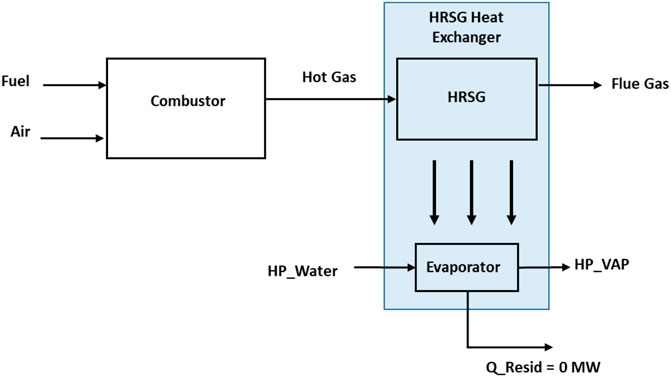
FIGURE 5. The boiler energy balance.
The boiler design pressure is 60 bars, and the water circulation rate is about 735.6 kg/s. A blower provides the needed compressed air of 29.14 kg mol/sec (see Eq. 9) to mix with 2.55 kg mol/sec of methane gas from the NGL recovery plant for combustion. Hot gas is produced through the HRSG to generate steam in the boiler exchanger. The boiler superheater is neglected within the control volume, and the heat releases to the ambient in the model are controlled.
4.3 Energy Result and Discussion
The gas composition, mass flow rates, temperatures, and pressures for each material stream have been set in Aspen HYSYS and Aspen Plus, respectively, upon which the energy of each stream is calculated. The result of the simulation from the Aspen HYSYS model is shown in Appendix A (Supplementary Appendix A Tables S2, S3). The specific energy of the waste gas is measured as a low-heat value (LHV) of 48,154 kJ/kg for the NGL recovery plant and 50,035 kJ/kg for the methane gas to the steam power plant. The difference in these calorific values is due to stream composition and molar flow rates in each of the plants. The total energy flow relative imbalance on the NGL recovery and the steam power plants amounts to 0.0 and 0.0%, respectively. With the zero-percentage error from the energy balance, the plants’ design can be said to be coherent with the energy accounting in line with the thermodynamics first law (Bejan, 1988). Appendix B (Supplementary Appendix B Figure S7 and Supplementary Appendix B Figure S8) compares the energy and exergy efficiencies of each of the components in the integrated plant, as well as the overall energy efficiencies for each of the plants. Appendix A (Supplementary Appendix A Table S7) shows the overall NGL recovery plant energy efficiency as 51.9%. The turbo-expander was connected to the third state compressor to reduce energy waste from the turbo-expander during the cryogenic process of delivering cold stream energy at −219°C from the unit into the demethanizer column. This cold energy was further charged by the reboiler heat to warm up the produced gas to about −128.5°C at the outlet of the demethanizer column. This lean gas delivered the cold energy through HEXs 103 and 104 to warm the gas to about 129.5°C at the combustor inlet of the steam power plant.
On the steam power plant, it is observed from the simulation that too much heat energy had been generated from the combustion side of the boiler to energize water to steam. To utilize produced heat, a certain parameter is adjusted to increase the circulating water rates till the residual heat energy (Q_Resid) becomes zero (see Figure 5). Analyzing the heat losses in the steam power plant, the major uncontrollable heat energy loss is from the flue gas. In this model, however, the flue gas temperature has been moderately reduced to about 120°C to achieve the minimum allowable stack temperature for natural gas (GPSA, 2012) that will prevent any liquid dropout and potential corrosion problems. In the condenser, the efficiency term is not used as the system-generated heat is lost to the environment. This heat rejection is important to complete the steam power plant cycle.
The overall fuel energy production in the combustor is 2047 and 1967 MW recovered at the HRSG with about 4% of generated heat lost to the environment as flue gas in Figure 6. In practice, heat energy loss from the flue gas release gets as much as 20–50% (Johnson et al., 2008; Bhatia, 2012). However, this heat loss from the flue gas may be recovered and utilized for the high-pressure water preheat in the inlet of the evaporator to further improve the steam power plant efficiency. The portion of the heat used to produce steam is quite high; hence, the application of superheat was ignored in the model to minimize heat energy waste. The steam power plant combustion and thermal efficiency were calculated as 96.1 and 32.6%, respectively, and Appendix A (Supplementary Appendix A Table S7) also indicates that the boiler and overall plant efficiencies are 87.2 and 31.3%, respectively. These efficiency values are simply based on the specific heat input to the steam and the low-heating value of the fuel. From the model, apart from the 4% heat energy loss as flue gas and 646.3 MW (32%) utilized for electricity, the condenser accounted for 1326 MW (65%) which is also released to the environment. From this result, it can be stated that energy analysis can be somewhat misleading because it appears to only deal with the quantity of energy and not energy quality. The reason is that this analysis did not consider energy losses due to irreversibilities and losses from process units or components such as the HEXs, condenser, or combustion chambers.
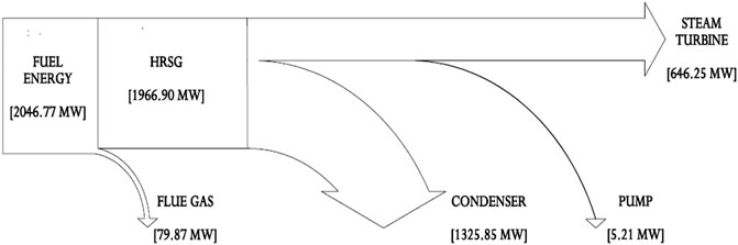
FIGURE 6. Sankey diagram of energy balance showing flow rates of energy.
5 Exergy Balance and Energy Analysis of the Integrated Plant Process
Bejan (1988) remarked that exergy can be transferred in three ways: work, heat transfer, and the movement of matter across control volume. He remarked that exergy can be destroyed within a control volume or a system by the process of irreversibilities:
In this study, process waste gas stream data (Table 1) are simulated to generate a process flowsheet that will help calculate the destroyed exergy and exergetic efficiency of the system components. The exergy flow rate of a system can be classified as kinetic, potential, physical, and chemical exergy, and the specific exergy rate is defined by Eq. 11 as discussed elsewhere (Aljundi, 2009):
Exergy calculation is based on the two approaches, which are separated into physical and chemical components (Aljundi, 2009). The author further remarked that in addition to the physical and chemical exergies components, there is also the change of mixing exergies components. In this study, the physical part of exergy will be considered since no evidence of chemical substances’ departure from the cycle to the environment is observed. Exergy defines the maximum work gained for the system in case of reaching the environmental conditions (Hinderink et al., 1996). Eq. 12 defines exergy loss as the difference between reversible and irreversible work, which is also called irreversibility, as presented in Eq. 16:
In any real process, the amount of entropy production is greater than or equal to zero, and exergy destruction always appears (Bejan, 1988; Bejan et al., 1996). Thus, the exergy destruction law is equal to the entropy generation (second law of thermodynamic) and determined from the Gouy-Stodola theorem (Anetor et al., 2016; Eshun, 2019) as stipulated in Eq. 13.
As mentioned, the exergy related to heat transfer
Thus, exergy destruction is basically due to the internal irreversibilities of a system and can be determined from exergy balance using Eq. 16 and Eq. 17:
The losses of exergy come from the exergy rejection to the environment, which is not used for anything (Bejan et al., 1996). Therefore, the lost exergy is destroyed, and the exergy loss rate
The estimation of boiler exergy efficiency requires the fuel exergy, and this is obtained from the correlation of the net calorific value discussed elsewhere (Kotas, 1995) and expressed in Eq. 20 and Eq. 21:
For most hydrocarbons, φCH4 = 1.06 (Zueco et al., 2020), and in this model HYSYS obtained the LHVCH4 = 802,703 kJ/kmol and HHVCH4 = 884,723 kJ/kmol. For other gaseous fuels heating values, refer to (Kotas, 1995). Alternative methods to determine fuel exergy are recommended by Szargut and Styrylska (1964). Therefore, Eq. 22 describes the mass balance equation for the process of combustion (Zueco et al., 2020):
where
In the condenser, heat energy is rejected to the environment, and this rejection is required to have a complete power cycle. Condenser irreversibility
Besides exergy destruction and exergy loss rates, Table 5 provides basic data on the inefficiencies and other parameters of the system (Bejan et al., 1996). However, the exergy loss rate in a specific component k can be compared with the exergy loss rate of the entire system, and they can be used to improve and determine components that require focus as expressed in Eqs 27–29. By definition, the exergy destruction ratio for the kth component
The exergetic efficiency
5.1 Exergy Destruction and Efficiencies in the Integrated Plant
All the equipment in this model experienced exergy destruction. Appendix A (Supplementary Appendix A Table S3) provides equations for exergy destruction and Figure 7 and Figure 8 present the percentage exergy destruction values of each of the components in the form of pie charts. Figure 9, Figure 10, and Appendix B (Supplementary Appendix B Figure S7 and Supplementary Appendix B Figure S8) present the percentage of the component’s exergetic efficiencies and overall efficiencies for the NGL recovery and the steam power plants, respectively.
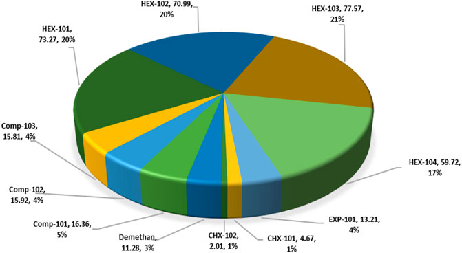
FIGURE 7. Exergy destroyed in the NGL recovery process plant.
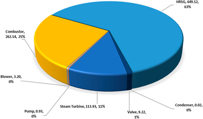
FIGURE 8. Exergy destroyed in the steam power process.
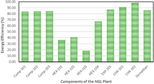
FIGURE 9. Exergy efficiency of components in the NGL recovery plant.
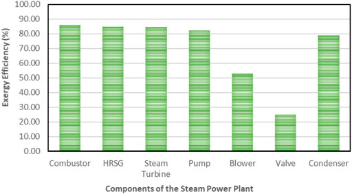
FIGURE 10. Exergy efficiency for all the components in the steam power plant.
5.1.1 Exergy Destruction and Losses in NGL Recovery Plant
In this simulation model, natural gas at 2 bars is compressed to 91.5 bars at a compression ratio of 3.58 and causes exergy destruction from high discharge temperature and pressure in the compressors. The exergy destruction of the compressors is smaller compared to the HEXs and turbo-expanders. The observed destruction may also be due to the multistage arrangement of the compressor, which had been designed to match the high natural gas flow rate. It is obvious from Figure 9 that the HEXs are the least efficient in the NGL recovery plant. This is due to the large exergy destruction from the compressors’ high outlet temperatures and the rapid cooling produced when the downstream gas passes through the interstage HEX. This irreversible condition causes the HEX to be inefficient due to the large log mean temperature difference (LMTD) of the HEXs at low temperatures. Figure 6 depicts the percentage of exergy destruction of the NGL system clearly. The exergy destruction of the HEX-104 was small relative to the rest of the exchangers because of the low-heat exchange load from this process-process gas HEX stream. The exergy destruction of the chillers is typically very small because the outlet temperature is very low and a lot less exergy destruction is produced. The exergy destroyed in the turbo-expanders is quite significant because the turbo-expander drives the compressor and enlarges the expansion ratio in the process of generating refrigeration from the process gas. Other than exergy destruction, loss exergy is also found in the demethanizer of the NGL recovery plant. The exergy analysis of the demethanizer was based on efficiency parameters calculation, exergy loss, and the Carnot factor. All these data, except for efficiency, are generated from the Aspen Plus, as shown in Figure 8. Although methodologies such as risk-based optimization and exergy-pinch analysis are often used for NGL recovery optimization, this work is focused essentially on the demethanizer exergy loss analysis only. Exergy loss in the demethanizer is a combination of all irreversibility due to heat transfer in reboilers, change in inlet feed pressure at feed stage, and finally Gibb’s energy of mixing across the stages. Appendix B (Supplementary Appendix B Figure S6) shows the significant impact of irreversibility in stage-10 location, where a huge amount of surplus of heat exists. In contrast, Appendix B (Supplementary Appendix B Figure S6) shows that the rectifying and stripping sections of the demethanizer column have a surplus of heat to be removed by a heat sink.
As seen from Appendix B (Supplementary Appendix B Figure S6), the intersection of the heat curve with the x-axis (stages number) shows that there is no border between the rectifier and stripper sections of the column. Thus, any feed can be applied to the column regardless of the temperature of the feed points. The chart has shown the reboiler position to the point where 2.3 MW heat is applied. It could be seen that, as the heat surplus/deficit approaches the datum point, exergy loss or system irreversibility gets smaller. The amount of needed heating (though small) is achieved with an electric fuel gas heater in the reboiler since no heat energy enters the system and all thermal energy leaving the system is destroyed.
5.1.2 Exergy Destruction and Losses in Steam Power Plant
Combustion and heat transfer are the two most important processes in a boiler. Thus, the exergy destruction and exergy losses in the system are exergies due to work and heat transfer. In this study, exergy losses because of friction from heat transfer are negligible. The results of the exergy analysis are presented in Figure 10 and Figure 11. The high exergy destruction in the steam power cycle is due to the high calorific value of fuel in the cycle. Otherwise, the steam cycle does not display substantial exergy destructions since the working fluid is steam produced through the steam cycle process.
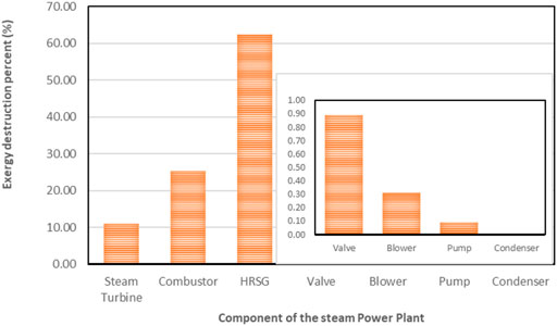
FIGURE 11. Exergy destruction percent for the components in steam power plant process.
The exergy destructions data in the steam power plant system are shown in Table 5 and displayed in a pie chart in Figure 10. In the condensers, a large quantity of heat energy enters it, and nearly all of it is dissipated to the environment. This analysis observed that an infinitesimal amount of exergy was destroyed in the condenser, thus indicating that the condenser is responsible for little or no losses in Table 5. The steam turbine also contributed to large exergy, as shown in Figure 7. This is possible because of the large expansion ratio that enables it to significantly drop its inlet high temperature and pressure to near environmental conditions. The exergy destruction on the blower, pump, and valve is significantly low and does not pose a concern in this analysis. However, the system exergy efficiency of the steam power plant is shown in a bar chart in Figure 10.
5.1.2.1 Data Accuracy
In terms of mass and energy balances, the relative deviations between mass inflow and outflow of the NGL recovery and the steam power plants are zero value, respectively, as shown in Appendix A (Supplementary Appendix A Table S2). Errors from the mass balance and energy balance are unfounded, and any possible contributions of potential and kinetic exergy are negligible. These energies also have no impact on the system energy or exergetic efficiency since the feed and product streams (except for the lean gas stream off the demethanizer) are assumed to enter and leave the column at relatively same elevations. However, in a real situation, the feed and product stream level does not necessarily enter and leave the process at the same elevations. Thus, the neglect in height difference may cause a small error in the simulation. Some destroyed exergy may have been allocated in error to process units, as measured process data are used in the simulation, as well as the impact from pressure fluctuations due to potential level differences. All cooling in the heat exchangers (HEX-101 and HEX-102) is done via cooling water discharged to the sea irreversibly. The exergy dissipated from the system in the form of heat energy is regarded as destroyed exergy. However, in practice, this means that the system is bound with the surrounding at points where the cooling water mixes with seawater. The chemical exergy component in the stream is excluded in this analysis due to its high calorific value from the gas entering and leaving each control volume. The major destroyed exergies distributed on each process are given in Figure 7 and Figure 12, portrayed by pie and bar charts on exergy destruction, respectively.
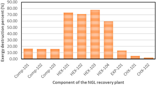
FIGURE 12. Exergy destruction percent for the components in the NGL recovery process.
5.1.2.2 Validation
In this study, the results of the NGL recovery have been compared with similar recovery, as shown in Table 3. The model validation accurately represents the process property of the NGL recovery plant and thus brings to bear the robustness and viability of the model in line with the work done by Mehrpooya et al. (2006); Getu et al. (2013); and Ghorbani et al. (2017). The plant operating data, such as the temperature, pressure, and flow rate, are typical measured values obtained from the back end of an operating field. Despite the model’s uniqueness, it is in conformance with conventional engineering procedures for NGL recovery. However, another model of similar recovery is selected based on their outcome and minimal operational dynamics. A summary of the model validation in Table 3 indicates that the model result is consistent with the plant data, thus affirming the model’s accuracy. Table 3 and Table 4 show marked variances between the stream compositions, operating parameters, flow rates, fuel types, and power generated. This accounts for the different results found in the models presented. However, the similarities in the simulators and equipment are used to validate the outcome of these models.
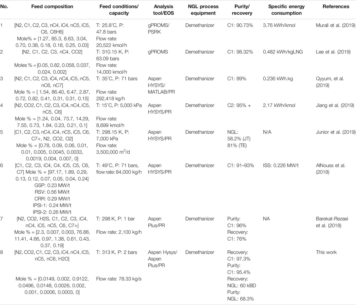
TABLE 3. Model validation summary on NGL recovery plant.

TABLE 4. Model validation summary on steam power plant.
In the NGL recovery plant, the focus was on the quantity and quality of the product recovery. It is seen that most of the results indicated the quantity of methane gas recovered, which ranged from 89 to 98%. On the contrary, when NGL recovery is the focus, as shown in Table 3, no result is presented on the recovered methane gas. As shown, about 58–81% NGL is recovered depending on whether a Joule–Thomson (J-T) valve or a turbo-expander is used during recovery. This study has shown that 97.3% of methane gas with 95% purity and 60 KBD of NGL at 68% purity are recovered simultaneously. This definitely improves the existing work, which tends to be limiting the results achieved.
On the contrary, the steam power plant performance is measured on a different set of properties. The energy efficiency and exergy efficiency provided in the reference table indicated a range of 21–38% for these thermal systems again depending on fuel type and flow rate. For this study, while the energy efficiency of 32.6% is within range, the exergy efficiency is significantly improved to 80.63%. The higher exergy efficiency achieved may be due to high power delivery following the boiler exchanger configuration. From the first law of thermodynamic, it is observed that the condenser is consistently the main component for energy rejection from the steam power plant as compared to the boiler, which indeed is responsible for exergy destruction (see Table 4). These findings, as enumerated in the reference table, are also consistent with the findings in this study.
5.2 Result and Discussion on the Exergy Study
In the oil and gas industry, refrigeration cycles play an exceptional role in the provision of energy for cryogenic processes of component separations (i.e., NGL recovery and other low-temperature purification processes). The design of such energy systems must be optimal to enhance product quality, energy efficiency, and overall plant profit. The degrees of freedom for the design of refrigeration systems can include varying parameters, such as pressure and temperature levels, composition, and a number of refrigeration stages. Furthermore, as these elements are considered, the design becomes increasingly complex. To determine which of these components contributes energy to the system, the system was evaluated broadly as productive and dissipative energy components. The productive components provide functional products such as fuel to other components within the system, and the dissipative component is one in which exergy is destroyed without any thermodynamic gain of useful energy in the same component. Table 5 more generally describes the components under the categories mentioned. The operation of dissipative components becomes meaningful when the components are evaluated based on the overall thermal system. During optimization, the dissipative components complemented the productivity in the system, wherever it was possible, to reduce the exergy destruction of the system components. It is believed that such complementary effort will help reduce the investment costs of the overall system or help maintain required emission standards in the case of this study. For example, an intercooler preceding a compressor reduces the power required for operating the compressor. In this study, the multistage compressors destroyed exergy by compression of low-pressure inlet gas through intercoolers to bring down interstage temperatures. In order words, a meaningful exergetic efficiency can only be defined if the intercooler, in this case, were to be considered together with the preceding compressor (Lazzaretto and Tsatsaronis, 2006). It is, therefore, important to notice that the condenser is classified as a dissipative component in this study because the remaining steam exergy from the steam turbine is dissipated to the environment via heat transfer.
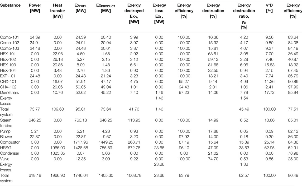
TABLE 5. Fuel and product exergy of components of the integrated plant.
The exergy destruction ratio is useful for locating and evaluating the sources of thermodynamic inefficiencies or irreversibilities by helping identify the portion of exergy destruction within the plant and the exergy analysis results in Table 5. The total exergy destruction on the NGL recovery plant amounts to 42 MW, and the HEX accounts for over 78% of these irreversibilities in the NGL recovery plant due to its large log mean temperature difference (LMTD). The most fundamental way to improve the exergetic efficiency of the HEX is by reducing the huge temperature difference between the process gas and cooling water streams. The high exergy destruction from the compressed gas cooling and the dissipation of the heated water (with temperature over 70°C) into the sea of temperature To shows that potential exists in this water for exploitation. However, the exergy relating to this disposed water may be hard to utilize due to its low temperature. Otherwise, it should be possible to eliminate the reboiler and chillers electric heaters and integrate the same with one of the warmest compressed gas process streams. On the contrary, waste heat from the steam turbines is sufficient at higher temperatures to compensate for any limited thermal energy required in the NGL recovery plant. Therefore, additional optimization of the heat exchangers would be required for exergy losses reduction. The exergy destruction of the chillers is small because of the low outlet stream temperature. The exergy destroyed in the turbo-expanders accounts for 4% of the overall destroyed exergy in the NGL recovery plant. The reason is that the turbo-expander enlarges the expansion ratio in the process of generating refrigeration from the process gas and also as compressor driver. The exergy destroyed in the turbo-expander can be reduced effectively via a dual or multistage expansion turbine. Other ways to reduce exergy losses in the turbo-expander are properly selecting the inlet pressure and improving the adiabatic efficiency. This will help enhance high efficiencies yield even at an off-design point. Exergy loss in the demethanizer is a combination of all irreversibility due to heat transfer in reboilers and the heat required to sustain the temperature gradient of the columns (Rivero, 2002). Other causes are changes in the inlet gas pressure at the feed stage and Gibb’s energy of mixing streams across the column stages. The exergy destroyed and exergy loss from the demethanizer account for about 3 and 1.54%, respectively, relative to the overall NGL recovery plant system. Although the column exergy destruction is small relative to the overall NGL recovery plant, it still amounts to a non-negligible quantity of the overall exergy input. Thus, to reduce exergy loss in the column, heat source or side reboilers of stage 30 could be disintegrated in a process known as thermal targeting, which helps allocate heat source or reboilers duty along the cryogenic column as discussed by Linnhoff and Dhole (1992); Bandyopadhyay et al. (1998); and Shin et al. (2015).
The exergy destructions observed in the overall steam power plant could be split into two thermodynamic irreversibilities. Firstly, irreversibility due to heat transfer over a finite temperature difference (Mago et al., 2008) in the case of the combustor in this study and irreversibility due to work done with the steam turbine (Barzegar Avval et al., 2011). However, while exergy destruction contributed from the large temperature differences between the hot and cold streams remain significant, the exergetic analysis of these components indicate that the gas composition variation may also have a significant effect on the steam power plant cycle.
The total destroyed exergy on the steam power plant is 1039 MW (see Figure 13), with about 88% of this attributed by the boiler assembly (63% HRSG exchanger and 25% to the combustor) as shown in Table 5 and Figure 8, respectively. Therefore, the boiler exchanger (combustor and HRSG) is the lowest efficient component of the steam power plant. Theoretically, the exergy destruction in the combustor could be minimized by tampering with the air-to-fuel ratio (Bejan et al., 1996) and combustion gas molar fraction modification (Jamnani and Kardgar, 2020). The implication, therefore, is that the combustion temperature will increase toward the destructive adiabatic flame temperature, which can lead to thermal stress and cause significant impacts to the lifespan of the components. The steam turbine follows and accounts for about 11% of the overall destroyed exergy in the steam power plant due to its high-temperature inlet steam. This exergy destruction can be reduced by adding a reheating device to the plant. A large quantity of heat energy (1326 MW) enters the condenser, and close to 100% of this energy is dissipated or rejected. From energy analysis results, it is often uncomfortably concluded that the heat rejection associated with condensers in the steam power plant is the cause of losses in electricity generation. However, the exergy analysis suggests otherwise by demonstrating that the condensers exhibit dissipative properties. Therefore, the condenser is responsible for little or no losses, as shown in Appendix A (Supplementary Appendix A Table S9). This discrepancy arises in this study based on the assumption that the system boundaries used for analyzing the exergy balances of the condenser are at the reference temperature
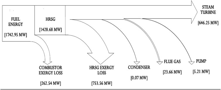
FIGURE 13. Sankey diagram of exergy balance showing flow rates of exergy.
5.3 Thermodynamic Performance Parameters of Exergy in the Oil and Gas Industry
As shown, the exergetic efficiency of the NGL recovery process from waste gas to energy and the associated parameters have been calculated. These parameters and data can be incorporated into the oil and gas industry performance measurements, including emissions. The exergetic efficiency can be used to justify and quantify the industry best practices in the management of waste gas to energy. The exergy analysis methodologies can also be used to set performance standards by the public sector. Such standards could lead to the development of more energy-efficient technologies and their best practices. This study has so far only examined the deposition of waste gas from oil and gas processing. It is proposed that sweetened produced mainstream gas are analyzed by exploring exergy analysis applications, especially when evaluating a series of produced gas streams, just to see how exergy analysis can be adapted to changing operating and process conditions for reasonable process safety and value creation (Afzal et al., 2021; Attia et al., 2021; Benoudina et al., 2021; Fayaz et al., 2021; Prasad et al., 2021).
6 Sensitivity Analysis in the Demethanizer Column
Sensitivity analysis was conducted to determine the impact of operating parameters’ key components on the NGL recovery plant profit using AspenOne Plus V10. It was seen that the operating parameters and range determine the energy utilization and output product. It was also observed that the expansion refrigeration process in the turbo-expander provided the cold energy that resulted in the extremely low temperatures in the demethanizer column. The low outlet pressure of the turbo-expander significantly affects the NGL (C2+) recovery. Appendix B (Supplementary Appendix B Figures S5, S6) shows that the energy loss in the column decreases as the pressure and temperature increases, which is essential because the stream in the demethanizer column has predominantly cold energy at low pressure. However, as the pressure increases from the column top to bottom, so also is the increase in the condensation of recovered product (C2 and heavier hydrocarbons) at the bottom of the demethanizer. At the same time, the lean gas ascends to the top of the column. This result brings about product profitability from the sales of recovered NGL as well as the conversion of the produced lean gas for power generation through the gas combustion process, which also will generate revenue.
Notably, the NGL market price is higher than the liquefied petroleum gas (LPG). Therefore, the demethanizer reflux ratio should not exceed 1.0 in order to minimize a possible declining rate of NGL recovery Appendix B (Supplementary Appendix B Figures S9, S10), which may occur due to energy loss in the column. For the benefit of the doubt, the demethanizer column height should be sufficient to enhance the hydrocarbon mixture separation efficiently. The straight line on the pressure curve in Appendix B (Supplementary Appendix B Figure S11) shows that below stage 10, most parts of the column wanted to create the height that is needed to enhance separation. Otherwise, the recycled gas from the column top is unable to reduce the total energy required and loss exergy in the column.
7 Optimization
7.1 NGL Recovery Plant Process
Certain notable parameters, including the compressor outlet pressure, choice of utilities, column pressure, and gas feed position into the column, affect product recovery and consumed energy. These parameters interface with one another to impact the NGL recovery and profitability. Generally, Aspen Plus was used as the optimization tool despite being less effective in certain cases with many variables and complexities, leading to optimization failure or possible premature convergence. To make the optimization procedure more efficient, we analyzed the parameters and identified the most appropriate optimization method (Uwitonze et al., 2016; Murali et al., 2019). Based on an NGL recovery engineering process, from waste gas to energy, this study focused on optimizing NGL recovery while also using the recovered lean gas for power generation. The cold energy of the feed stream is required to enhance the C2+ and heavier hydrocarbons separation from the more volatile methane component of the feed. The reflux ratio across the demethanizer plates not only increases the component separation efficiency and its product purity but also aids the demethanizer energy consumption. The reflux ratio increased during optimization to about 17% to reach the desired product specifications of about 95% pure methane and 68% NGL. The boil-up ratio is observed to decrease to 0.8 (80%) during optimization. This decrease shows that less liquid is reboiled back into the demethanizer, which is necessary to reduce the steam reboiler heat energy consumption.
In this work, the optimization analysis showed that the recycled gas stream was more effective with a 30-stage column than in the 18-stage as the required head to enhance reflux action and delivery of standardized products was achieved. Appendix A (Supplementary Appendix A Table S6) shows the exergy loss profiles for the column, and Appendix A (Supplementary Appendix A Table S8) summarizes the products of the optimized variables in the 30-stage column. The optimization of the gas subcooled process, cold residue reflux process, and recycle split vapor process resulted in an overall exergy loss reduction to about 1.54% in the NGL recovery plant. In the gas subcooled process, it is observed that more vapor flows in the feed gas, as well as in the rectifying section on the column. This helped deliver improved and efficient separation around the rectifying section and possibly increased exergy loss in the demethanizer. Much more than increasing the exergy loss at the column top, the vapor flow condition will also bring about a reduction in exergy destruction around the stripping section of the column. This brought down exergy destruction to 1.49 MW and the exergy loss in the column to 1.46 MW. The increase in the adiabatic efficiencies of the multistage compressors from 75 to 85% boosted the turbo-expander inlet pressure but increased the exergy destroyed in the compressors and interstage coolers (HEX) than expected with no significant heat load to the interstage HEXs from temperature rise. On the contrary, the increase in the turbo-expander adiabatic efficiencies from 75 to 85% not only increased the NGL yield and introduced the cold energy in the column, but also significantly dropped discharge pressure and isentropic efficiency to about 65%, while increasing exergy destruction and the load from the driven compressor. This exergy destruction is the direct result of deliberately increasing gas pressure in the demethanizer to enhance the desirable NGL striping. Although the drop in the turbo-expander isentropic efficiency is essentially due to the work done on the compressor, it is observed that if a dual or multistage expander is utilized, the isentropic efficiency will improve.
7.2 Steam Power Plant Process Optimization
To utilize produced heat from the HRSG, a certain parameter was adjusted to increase the circulating water rates till the residual heat energy (Q_Resid) becomes zero. This optimization helped to ensure that possible duty losses in the steam side or the environment were curtailed. From the Aspen HYSYS simulation, the components heat rates, the mass flow rate (fuel and air, steam), and power are determined. Table 5 shows these values and the thermodynamic characteristics of the streams, that is, fuel and product exergy, exergy destruction, exergy loss, and exergy efficiency associated with each component. The optimization achieved in the steam turbine increased the power delivery to 646.3 MW when the adiabatic efficiency was increased from 75 to 85%. This was done by dropping the steam turbine discharge pressure to as low as 0.032 bars. In this optimization, the steam turbine and the condenser were merged as a single component to exploit the dissipative property of the condenser, and it was found that the product of the steam turbine could not be defined (Bejan et al., 1996) for the condenser despite its high exergetic efficiency of 79%. However, the importance of environmental emission from the flue gas release is a challenge with fossil fuels energy conversion systems. To this end, the blower was configured to deliver excess 20% air at the right quantity of lean low-pressure gas to ensure optimal combustion and minimize emissions from flue gas releases to the environment.
8 Conclusion
The benefits of exergy analysis are numerous, relative to energy analysis, especially in complex process systems such as the oil and gas industry, where exergy methods have not been adapted sufficiently to assess the thermodynamic values of the various energy (product) forms. The exergetic efficiency of components considers the minimum work that may be done theoretically in or for a given process. With exergy analysis, destroyed exergy for different parts of production processes can be calculated to determine areas or locations where improvement is required. In this study, the exergy destruction location and magnitude, as well as exergetic efficiency in each component and the entire integrated plant system, were determined.
NGLs recovery plants, as typical process plants, require continuous adaptation in technologies and innovations. This will aid suitable operating conditions selection to safely optimize component design, improve equipment performance, and increase profitability. Therefore, this research work achieved its set objective by stripping NGL off waste gas while also utilizing the residue lean gas in a hot steam generation to produce electricity. This work reassures the mainstream of the oil and gas industry of the enormous potential benefit it can achieve when the concept of exergy analysis is adopted in the modeling and designs of oilfield facilities. The optimal energy conversion process from fossil fuels is a requirement for emissions mitigation. This study, therefore, readily proposes a new perspective of helping the industry to embrace the concept of flare-capturing conversion to wealth rather than the burden which has encompassed flaring practices from inception. It is also demonstrated that waste gas to energy is a viable and valuable strategy for the stakeholders in the oil and gas processing industries to enhance energy security (Voldsund, 2014) around the world.
The produced lean gas, in turn, undergoes an energy conversion process to generate steam for electric power production via a steam power plant. Among the highly irreversible processes, CO2 from flue gas is minimized by stoichiometrically oxidizing the combustion process. This approach helped in optimizing and improving the adiabatic flame temperature and reduced the potential for uncontrollable CO2 emissions. All components of the integrated plant systems demonstrated some forms of irreversibility. The exergy analysis results indicated that the highest exergy destruction and the lowest efficiencies come from the heat exchangers, while the only exergy loss belongs to the demethanizer column, in the NGL recovery plant and the boiler assembly in the steam power plant, whereas the same occurred in the HRSG and combustor, respectively.
Data Availability Statement
The raw data supporting the conclusion of this article will be made available by the authors without undue reservation.
Author Contributions
PA: investigation, methodology, and writing—review and editing. IE: conceptualization, formal analysis, writing—original draft, and writing—review and editing. OS: conceptualization, formal analysis, and writing—review and editing. CC: conceptualization, writing—original draft, and writing—review and editing. AA: formal analysis and writing—review and editing.
Conflict of Interest
The authors declare that the research was conducted in the absence of any commercial or financial relationships that could be construed as a potential conflict of interest.
Publisher’s Note
All claims expressed in this article are solely those of the authors and do not necessarily represent those of their affiliated organizations or those of the publisher, editors, and reviewers. Any product that may be evaluated in this article, or claim that may be made by its manufacturer, is not guaranteed or endorsed by the publisher.
Acknowledgments
The author T. Abdeljawad would like to thank Prince Sultan University for support through the TAS Research Lab.
Supplementary Material
The Supplementary Material for this article can be found online at: https://www.frontiersin.org/articles/10.3389/fenrg.2021.798896/full#supplementary-material
References
Abam, F. I., Diemuodeke, O. E., Ekwe, E. B., Alghassab, M., Samuel, O. D., Khan, Z. A., et al. (2020). Exergoeconomic and Environmental Modeling of Integrated Polygeneration Power Plant with Biomass-Based Syngas Supplemental Firing. Energies 13 (22), 6018. doi:10.3390/en13226018
Abdollahi-Demneh, F., Moosavian, M. A., Omidkhah, M. R., and Bahmanyar, H. (2011). Calculating Exergy in Flowsheeting Simulators: A HYSYS Implementation. Energy 36 (8), 5320–5327. doi:10.1016/j.energy.2011.06.040
Afzal, A., Alshahrani, S., Alrobaian, A., Buradi, A., and Khan, S. A. (2021). Power Plant Energy Predictions Based on Thermal Factors Using Ridge and Support Vector Regressor Algorithms. Energies 14 (21), 7254. doi:10.3390/en14217254
Ahmadi, G. R., and Toghraie, D. (2016). Energy and Exergy Analysis of Montazeri Steam Power Plant in Iran. Renew. Sustain. Energ. Rev. 56, 454–463. doi:10.1016/j.rser.2015.11.074
Aljundi, I. H. (2009). Energy and Exergy Analysis of a Steam Power Plant in Jordan. Appl. Therm. Eng. 29 (2-3), 324–328. doi:10.1016/j.applthermaleng.2008.02.029
AlNouss, A., Ibrahim, M., and Al-Sobhi, S. A. (2018). Potential Energy Savings and Greenhouse Gases (GHGs) Emissions Reduction Strategy for Natural Gas Liquid (NGL) Recovery: Process Simulation and Economic Evaluation. J. Clean. Prod. 194, 525–539. doi:10.1016/j.jclepro.2018.05.107
Ameri, M., Ahmadi, P., and Khanmohammadi, S. (2008). Exergy Analysis of a 420 MW Combined Cycle Power Plant. Int. J. Energ. Res. 32, 175–183. doi:10.1002/er.1351
Amir, V. “Improving Steam Power Plant Efficiency through Exergy Analysis: Ambient Temperature,” in Proceedings of the 2nd International Conference on Mechanical, Production and Automobile Engineering (ICMPAE'2012), Singapore, April 2012, 209–212.
Anetor, L., Osakue, E. E., and Odetunde, C. (2016). Exergetic Analysis of a Natural Gas-Burning Steam Power Plant. Aust. J. Mech. Eng. 15 (2), 137–147. doi:10.1080/14484846.2016.1188456
Ansarinasab, H., Afshar, M., and Mehrpooya, M. (2016). Exergoeconomic Evaluation of LNG and NGL Co-production Process Based on the MFC Refrigeration Systems. Iranian J. Oil Gas Sci. Technol. 5 (3), 45–61. doi:10.22050/IJOGST.2016.38530
API (1977). API RP 521 Guide for Pressure-Relieving and Depressuring Systems. Recommended Practice RP 521. Fourth Edition. Washington, DC: API.
Aspen Tech (2013). Jump Start: Activated Economics in Aspen Hysys V8. Available at: http://www.aspentech.com/ActivationAspenPlus.
Attia, M. E. H., Driss, Z., Kabeel, A. E., Afzal, A., Manokar, A. M., and Sathyamurthy, R. (2021). Phosphate Bed as Energy Storage Materials for Augmentation of Conventional Solar Still Productivity. Environ. Prog. Sustain. Energ. 40 (4), 1–9. doi:10.1002/ep.13581
Babaei Jamnani, M., and Kardgar, A. (2020). Energy‐exergy Performance Assessment with Optimization Guidance for the Components of the 396‐MW Combined‐cycle Power Plant. Energy Sci Eng 8, 3561–3574. doi:10.1002/ese3.764
Bandyopadhyay, S., Malik, R. K., and Shenoy, U. V. (1998). Temperature-enthalpy Curve for Energy Targeting of Distillation Columns. Comput. Chem. Eng. 22, 1733–1744. doi:10.1016/s0098-1354(98)00250-6
Barekat-Rezaei, E., Farzaneh-Gord, M., Arjomand, A., Jannatabadi, M., Ahmadi, M., and Yan, W.-M. (2018). Thermo-Economical Evaluation of Producing Liquefied Natural Gas and Natural Gas Liquids from Flare Gases. Energies 11 (7), 1868. doi:10.3390/en11071868
Barzegar Avval, H., Ahmadi, P., Ghaffarizadeh, A. R., and Saidi, M. H. (2011). Thermo-economic-environmental Multiobjective Optimization of a Gas Turbine Power Plant with Preheater Using Evolutionary Algorithm. Int. J. Energ. Res. 35 (5), 389–403. doi:10.1002/er.1696
Bejan, A., Tsatsaronis, G., and Moran, M. J. (1996). Thermal Design & Optimization. New York, USA: John Wiley & Sons.
Benjamin Eshun, R. (2019). Energy and Exergy Based Performance Analysis of Westinghouse AP1000 Nuclear Power Plant. Aas 4 (1), 1–10. doi:10.11648/j.aas.20190401.11
Benoudina, B., Attia, M. E. H., Driss, Z., Afzal, A., Manokar, A. M., and Sathyamurthy, R. (2021). Enhancing the Solar Still Output Using Micro/nano-Particles of Aluminum Oxide at Different Concentrations: An Experimental Study, Energy, Exergy and Economic Analysis. Sustain. Mater. Tech. 29, e00291. doi:10.1016/j.susmat.2021.e00291
Bhatia, A. (2012). Introduction to Material and Energy Balance. An Approved Continuing Education Provider. Available at: http://www.PDHcenter.com.
Bhran, A. A. E.-K., Hassanean, M. H., and Helal, M. G. (2016). Maximization of Natural Gas Liquids Production from an Existing Gas Plant. Egypt. J. Pet. 25 (3), 333–341. doi:10.1016/j.ejpe.2015.08.003
Brodyansky, V. M., Sorin, M. V., and Le Goff, P. (1994). The Efficiency of Industrial Processes : Exergy Analysis and Optimization. Netherlands: Elsevier Science BV.
Brückner, S., Liu, S., Miró, L., Radspieler, M., Cabeza, L. F., and Lävemann, E. (2015). Industrial Waste Heat Recovery Technologies: An Economic Analysis of Heat Transformation Technologies. Appl. Energ. 151, 157–167. doi:10.1016/j.apenergy.2015.01.147
Calvo, G., Valero, A., and Valero, A. (2018). Thermodynamic Approach to Evaluate the Criticality of Raw Materials and its Application through a Material Flow Analysis in Europe. J. Ind. Ecol. 22 (4), 839–852. doi:10.1111/jiec.12624
Caton, J. A. (2011). Exergy Destruction during the Combustion Process as Functions of Operating and Design Parameters for a Spark-Ignition Engine. Int. J. Energ. Res. 36 (3), 368–384. doi:10.1002/er.1807
Cengel, Y., and Boles, M. (2006). Thermodynamics - an Engineering Aproach. 5th ed. NY, USA: McGraw-Hill companies Inc.
Eisenmenger, N., Warr, B., and Magerl, A. (2017). Trends in Austrian Resource Efficiency: An Exergy and Useful Work Analysis in Comparison to Material Use, CO2Emissions, and Land Use. J. Ind. Ecol. 21 (5), 1250–1261. doi:10.1111/jiec.12474
Emam, E. A. (2015). Gas Flaring in Industry: An Overview. Pet. Coal 57 (5), 532–555. Available at: http://www.vurup.sk/petroleum-coal.
Fayaz, H., Afzal, A., Samee, A. D. M., Soudagar, M. E. M., Akram, N., Mujtaba, M. A., et al. (2021). Optimization of Thermal and Structural Design in Lithium-Ion Batteries to Obtain Energy Efficient Battery Thermal Management System (BTMS): A Critical Review. Arch. Computat Methods Eng. 29, 129–194. doi:10.1007/s11831-021-09571-0
Gao, C. Y. (2014). “Analysis on Domestic Ethylene Market in 2013 and Forecast in 2014,” in Coal Processing & Comprehensive Utilization. Editors D. V. S. Rao, and T. Gouricharan (Milton Park UK: Routledge), 47–50.2
Getu, M., Mahadzir, S., Long, N. V. D., and Lee, M. (2013). Techno-economic Analysis of Potential Natural Gas Liquid (NGL) Recovery Processes under Variations of Feed Compositions. Chem. Eng. Res. Des. 91 (7), 1272–1283. doi:10.1016/j.ch10.1016/j.cherd.2013.01.015
Ghannadzadeh, A., Thery-Hetreux, R., Baudouin, O., Baudet, P., Floquet, P., and Joulia, X. (2012). General Methodology for Exergy Balance in ProSimPlus Process Simulator. Energy 44 (1), 38–59. doi:10.1016/j.energy.2012.02.017
Ghorbani, B., Mehrpooya, M., Hamedi, M.-H., and Amidpour, M. (2017). Exergoeconomic Analysis of Integrated Natural Gas Liquids (NGL) and Liquefied Natural Gas (LNG) Processes. Appl. Therm. Eng. 113, 1483–1495. doi:10.1016/j.applthermaleng.2016.1110.1016/j.applthermaleng.2016.11.142
GPSA (1998). Section 16, Hydrocarbon Recovery. 11th edn Tulsa, OK. USA: Gas Processors Suppliers Association. SI Version.
Habib, M. A., Said, S. A. M., and Al-Zaharna, I. (1999). Thermodynamic Optimization of Reheat Regenerative thermal-power Plants. Appl. Energ. 63 (1), 17–34. doi:10.1016/s0306-2619(99)00017-3
Haris Hamayun, M., Hussain, M., Shafiq, I., Ahmed, A., and Park, Y.-K. (2021). Investigation of the Thermodynamic Performance of an Existing Steam Power Plant via Energy and Exergy Analyses to Restrain the Environmental Repercussions: A Simulation Study. Environ. Eng. Res. 27 (1), 200683. doi:10.4491/eer.2020.683
Hernandez, A. G., Cooper-Searle, S., Skelton, A. C. H., and Cullen, J. M. (2018). Leveraging Material Efficiency as an Energy and Climate Instrument for Heavy Industries in the EU. Energy Policy 120, 533–549. Available at: https://linkinghub.elsevier.com/retrieve/pii/S0301421518303586. doi:10.1016/j.enpol.2018.05.055
Hinderink, A. P., Kerkhof, F. P. J. M., Lie, A. B. K., De Swaan Arons, J., and Van Der Kooi, H. J. (1996). Exergy Analysis with a Flowsheeting Simulator-I. Theory; Calculating Exergies of Material Streams. Chem. Eng. Sci. 51 (20), 4693–4700. Available at: https://www.infona.pl/resource/bwmeta1.element.elsevier-ff9d23c4-e3fa-30f4-97d1-caf396a872d4. doi:10.1016/0009-2509(96)00220-5
Hou, D., Shao, S., Zhang, Y., Liu, S. L., Chen, Y., and Zhang, S. S. (2012). Exergy Analysis of a thermal Power Plant Using a Modeling Approach. Clean. Techn Environ. Pol. 14 (5), 805–813. doi:10.1007/s10098-011-0447-0
Iandoli, C. L., and Kjelstrup, S. (2007). Exergy Analysis of a GTL Process Based on Low-Temperature Slurry F−T Reactor Technology with a Cobalt Catalyst. Energy Fuels 21 (4), 2317–2324. doi:10.1021/ef060646y
Isichei, A. O., and Sanford, W. W. (1976). The Effects of Waste Gas Flares on the Surrounding Vegetation in South- Eastern Nigeria. J. Appl. Ecol. 13 (1), 177. doi:10.2307/2401936
Ismail, O. S., and Umukoro, G. E. (2012). Global Impact of Gas Flaring. Epe 04, 290–302. doi:10.4236/epe.2012.44039
Jafaryani Jokandan, M., Aghbashlo, M., and Mohtasebi, S. S. (2015). Comprehensive Exergy Analysis of an Industrial-Scale Yogurt Production Plant. Energy 93, 1832–1851. doi:10.1016/j.energy.2015.10.003
Jiang, H., Zhang, S., Jing, J., and Zhu, C. (2019). Thermodynamic and Economic Analysis of Ethane Recovery Processes Based on Rich Gas. Appl. Therm. Eng. 148, 105–119. doi:10.1016/j.applthermaleng.2018.11.046
Johnson, I., Choate, W. T., and Davidson, A. (2008). Waste Heat Recovery. Technology and Opportunities in U.S. Industry. United States: US Dept. of Energy, Office of Energy Efficiency and Renewable Energy. doi:10.2172/1218716
Jouhara, H., Khordehgah, N., Almahmoud, S., Delpech, B., Chauhan, A., and Tassou, S. A. (2018). Waste Heat Recovery Technologies and Applications. Therm. Sci. Eng. Prog. 6, 268–289. doi:10.1016/j.tsep.2018.04.017
Junior, S. A., Meneguelo, A. P., Arrieche, L., and Bacelos, M. (2019). Assessment of a Process Flow Diagram for NGL Recovery Using Different Condensation Mechanisms. Comput. Chem. Eng. 130, 1–13. doi:10.1016/j.compchemeng.2019.106557
Kaşka, Ö. (2014). Energy and Exergy Analysis of an Organic Rankine for Power Generation from Waste Heat Recovery in Steel Industry. Energ. Convers. Manage. 77, 108–117. doi:10.1016/j.enconman.2013.09.026
Khaliq, A., and Kaushik, S. C. (2004). Second-law Based Thermodynamic Analysis of Brayton/Rankine Combined Power Cycle with Reheat. Appl. Energ. 78 (2), 179–197. doi:10.1016/j.apenergy.2003.08.002
Khan, M. S., Chaniago, Y. D., Getu, M., and Lee, M. (2014). Energy Saving Opportunities in Integrated NGL/LNG Schemes Exploiting: Thermal-coupling Common-Utilities and Process Knowledge. Chem. Eng. Process. Process Intensification 82, 54–64. doi:10.1016/j.cep.2014.06.001
Kotas, T. J. (1995). The Exergy Method of thermal Plant Analysis. Malabar, USA: Krieger Publishing Company.
Krishnakumar Dipak Pilankar, K. D., and Dr. Rajesh Kale, R. (2016). Energy and Exergy Analysis of Steam and Power Generation Plant. Ijert V5 (6). doi:10.17577/IJERTV5IS060478
Kwak, H., Kim, D. J., and Jeon, J. S. (2003). Exergetic and Thermoeconomic Analyses of Power Plants. Energy 28, 343–360. doi:10.1016/s0360-5442(02)00138-x
Lazzaretto, A., and Tsatsaronis, G. (2006). SPECO: A Systematic and General Methodology for Calculating Efficiencies and Costs in thermal Systems. Energy 31 (8-9), 1257–1289. doi:10.1016/j.energy.2005.03.011
Lee, Y., Lim, Y., and Lee, W. B. (2019). Integrated Process Design and Optimization of Nitrogen Recovery in Natural Gas Processing. Ind. Eng. Chem. Res. 58, 1658–1674. doi:10.1021/acs.iecr.8b04542
Linde natural gas plants (2005). State-of-the-art Nitrogen Rejection Technology, Increasing the Energy Density of Natural Gas. Available at: aHR0cDovL3d3dy5saW5kZS1lbmdpbmVlcmluZy5jb20vbnJ1.
Linnhoff, B., and Dhole, V. R. (1992). Shaftwork Targets for Low-Temperature Process Design. Chem. Eng. Sci. 47, 2081–2091. doi:10.1016/0009-2509(92)80324-6
Mago, P. J., Srinivasan, K. K., Chamra, L. M., and Somayaji, C. (2008). An Examination of Exergy Destruction in Organic Rankine Cycles. Int. J. Energ. Res. 32 (10), 926–938. doi:10.1002/er.1406
Malumfashi, G. I. (2007). Phase-Out of Gas Flaring in Nigeria by 2008: The Prospects of a Multi-Win Project (Review of the Regulatory, Environmental and Socio-Economic Issues). Nigeria Gas Flaring Pet. Train. J. 4 (2), 1–39.
Manning, F. S., and Thompson, R. E. (1991). Oilfield Processing of Petroleum. Tulsa, USA: PennWell Publishing Company.
Marin, A., Dobrovicescu, A., Grosu, L., and Gheorghian, A. (2014). Energy and Exergy Analysis of an Organic Rankine Cycle. U.P.B. Sci. Bull. Ser. D 76 (4), 127–136.
Mehrpooya, M., Jarrahian, A., and Pishvaie, M. R. (2006). Simulation and Exergy-Method Analysis of an Industrial Refrigeration Cycle Used in NGL Recovery Units. Int. J. Energ. Res. 30 (15), 1336–1351. doi:10.1002/er.1256
Moran, M. J. (1982). Availability Analysis: A Guide to Efficient Energy Use. Englewood Cliffs, NJ, USA: Prentice-Hall.
Mourad, D., Ghazi, O., and Noureddine, B. (2009). Recovery of Flared Gas through Crude Oil Stabilization by a Multi-Staged Separation with Intermediate Feeds: A Case Study. Korean J. Chem. Eng. 26 (6), 1706–1716. doi:10.1007/s11814-009-02310.1007/s11814-009-0236-1
Murali, A., Berrouk, A. S., Dara, S., AlWahedi, Y. F., Adegunju, S., Abdulla, H. S., et al. (2019). Efficiency Enhancement of a Commercial Natural Gas Liquid Recovery Plant: A MINLP Optimization Analysis. Separat. Sci. Technol. 55, 955–966. doi:10.1080/01496395.2019.1574825
Nguyen, T.-V., Jacyno, T., Breuhaus, P., Voldsund, M., and Elmegaard, B. (2014). Thermodynamic Analysis of an Upstream Petroleum Plant Operated on a Mature Field. Energy 68, 454–469. doi:10.1016/j.energy.2014.02.040
Nur, T. B., and Sunoto, (2018). Exergy Analysis of Biomass Organic Rankine Cycle for Power Generation. IOP Conf. Ser. Mater. Sci. Eng. 309, 012057. doi:10.1088/1757-899X/309/1/012057
Ouadha, A., En-nacer, M., Adjlout, L., and Imine, O. (2005). Exergy Analysis of a Two-Stage Refrigeration Cycle Using Two Natural Substitutes of HCFC22. Ijex 2 (1), 14–28. doi:10.1504/ijex.2005.006430
Patel, P., Modh, J., and Patel, V. (2016). “Parametric Analysis of Organic Rankine Cycle (ORC) for Low Grade Waste Heat Recovery,” in Proceedings of the National Conference on Thermal Fluid Science and Tribo Application (TFSTA2016-50), May 2016Surat, Gujarat, 270–277.
Patel, S. S., and Agrawal, G. K. (2019). Investigation of Influencing Process Parameters to Energy and Exergy Efficiencies of a Coal Fired Thermal Power Plant Using Cycle Tempo. Int. J. Comput. Sci. Eng. 7 (3), 97–104.
Prasad, A. R., Attia, M. E. H., Al-Kouz, W., Afzal, A., Athikesavan, M. M., and Sathyamurthy, R. (2021). Energy and Exergy Efficiency Analysis of Solar Still Incorporated with Copper Plate and Phosphate Pellets as Energy Storage Material. Environ. Sci. Pollut. Res. 28 (35), 48628–48636. doi:10.1007/s11356-021-14080-5
Querol, E., Gonzalez-Regueral, B.., Ramos, A., and Perez-Benedito, J. L. (2011). Novel application for exergy and thermoeconomic analysis of processes simulated with Aspen Plus®. Energy 36 (2), 964–974. doi:10.1016/j.energy.2010.12.013
Qyyum, M. A., Qadeer, K., Minh, L. Q., Haider, J., and Lee, M. (2019). Nitrogen Self-Recuperation Expansion-Based Process for Offshore Coproduction of Liquefied Natural Gas, Liquefied Petroleum Gas, and Pentane Plus. Appl. Energ. 235, 247–257. doi:10.1016/j.apenergy.2018.10.127
Rahimpour, M., and Alizadehhesari, K. (2009). Enhancement of Carbon Dioxide Removal in a Hydrogen-Permselective Methanol Synthesis Reactor. Int. J. Hydrogen Energ. 34 (3), 1349–1362. doi:10.1016/j.ijhydene.2008.10.089
Rahimpour, M. R., Jamshidnejad, Z., Jokar, S. M., Karimi, G., Ghorbani, A., and Mohammadi, A. H. (2012). A Comparative Study of Three Different Methods for Flare Gas Recovery of Asalooye Gas Refinery. J. Nat. Gas Sci. Eng. 4, 17–28. doi:10.1016/j.jngse.2011.10.001
Rakopoulos, C., and Giakoumis, E. (2006). Second-law Analyses Applied to Internal Combustion Engines Operation. Prog. Energ. Combustion Sci. 32, 2–47. doi:10.1016/j.pecs.2005.10.001
Rivero, R. (2002). Application of the Exergy Concept in the Petroleum Refining and Petrochemical Industry. Energ. Convers. Manage. 43 (9-12), 1199–1220. doi:10.1016/s0196-8904(02)00008-0
Rosen, M. A., and Dincer, I. (2001). Exergy as the confluence of Energy, Environment and Sustainable Development. Exergy, Int. J. 1 (1), 3–13. doi:10.1016/S1164-0235(01)00004-8
Rosen, M. A. (2001). Energy- and Exergy-Based Comparison of Coal-Fired and Nuclear Steam Power Plants. Exergy, Int. J. 1, 180–192. doi:10.1016/s1164-0235(01)00024-3
Saidur, R., Ahamed, J. U., and Masjuki, H. H. (2010). Energy, Exergy and Economic Analysis of Industrial Boilers. Energy Policy 38, 2188–2197. doi:10.1016/j.enpol.2009.11.087
Salas, S. D., Geraili, A., and Romagnoli, J. A. (2017). Optimization of Renewable Energy Businesses under Operational Level Uncertainties through Extensive Sensitivity Analysis and Stochastic Global Optimization. Ind. Eng. Chem. Res. 56 (12), 3360–3372. doi:10.1021/acs.iecr.6b04395
Sciubba, E., and Wall, G. (2004). A Brief Commented History of Exergy from the Beginnings 2004. Int. J. Thermodynamics 10 (1), 1–26.
Shamet, O., Ahmed, R., and Nasreldin Abdalla, K. (2021). Energy and Exergy Analysis of a Steam Power Plant in Suda. Afr. J. Eng. Technol. 1 (1), 1–13. doi:10.47959/AJET.2021.1.1.4
Shengjun, Z., Huaixin, W., and Tao, G. (2011). Performance Comparison and Parametric Optimization of Subcritical Organic Rankine Cycle (ORC) and Transcritical Power Cycle System for Low-Temperature Geothermal Power Generation. Appl. Energ. 88 (8), 2740–2754. doi:10.1016/j.apenergy.2011.02.034
Shin, J., Yoon, S., and Kim, J.-K. (2015). Application of Exergy Analysis for Improving Energy Efficiency of Natural Gas Liquids Recovery Processes. Appl. Therm. Eng. 75, 967–977. doi:10.1016/j.applthermaleng.2014.10.042
Suryo, U. M. T., Yohana, E., Priyanto, S. D., Ignatius Apryando, M., and Tauviqirrahman, (2019). “Energy and Exergy Analysis of Steam Power Plant 3rd Unit PT PLN (PERSERO) Centre Unit Generation Tanjung Jati B Use BFP-T Modification Cycle,” in Proceedings of the The 4th International Conference on Energy, Environment, Epidemiology and Information System (ICENIS 2019), Semarang, Indonesia, August 2019, 125, 13003. doi:10.1051/e3sconf/201912513003
Szargut, J., and Styrylska, T. (1964). Approximate Evaluation of the Exergy of Fuels. Brennstoff Waerme Kraft 16 (12), 589–596.
Tahmasebi, S., Bavand Abbasabadi, A., Ghasemi, N., Javadian, H., Mashhadi, S., Fattahi, M., et al. (2015). Investigation of Various Feed Conditions on NGL Recovery Plant Energy and Exergy Performance: A Case Study. J. Nat. Gas Sci. Eng. 22, 83–89. doi:10.1016/j.jngse.2014.11.019
Tolulope, A. (2004). Oil Exploration and Environmental Degradation: The Nigerian Experience. Environ. Inform. Arch. 2, 387–393. Available at: https://www.scirp.org/(S(i43dyn45teexjx455qlt3d2q))/reference/ReferencesPapers.aspx?ReferenceID=1354299.
Uwem, U., and Akpan, E. B. (2017). Gas Flaring in Nigeria; Problems and Prospects. Glob. J. Polit. L. Res. 5 (1), 16–28.
Uwitonze, H., Lee, I., and Hwang, K. S. (2016). Alternatives of Integrated Processes for Coproduction of LNG and NGLs Recovery. Chem. Eng. Process. - Process Intensification 107, 157–167. doi:10.1016/j.cep.2016.05.006
Valencia, G., Fontalvo, A., Cárdenas, Y., Duarte, J., and Isaza, C. (2019). Energy and Exergy Analysis of Different Exhaust Waste Heat Recovery Systems for Natural Gas Engine Based on ORC. Energies 12, 2378. doi:10.3390/en12122378
Vatani, A., Mehrpooya, M., and Tirandazi, B. (2013). A Novel Process Configuration for Co-production of NGL and LNG with Low Energy Requirement. Chem. Eng. Process. process intensification 63 (63), 16–24. doi:10.1016/j.cep.2012.10.010
Voldsund, M. (2014). “Exergy Analysis of Offshore Oil and Gas Processing,” . Thesis for the degree of Philosophiae Doctor (Trondheim, Norway: Norwegian University of Science and Technology).
Wang, J.-J., Yang, K., Xu, Z.-L., and Fu, C. (2015). Energy and Exergy Analyses of an Integrated CCHP System with Biomass Air Gasification. Appl. Energ., 142, 317–327. doi:10.1016/j.apenergy.2014.12.085
Yoon, S., Binns, M., Park, S., and Kim, J.-K. (2017). Development of Energy-Efficient Processes for Natural Gas Liquids Recovery. Energy 128, 768–775. doi:10.1016/j.energy.2017.04.049
Yoon, S., Cho, H. J., Yeo, Y.-K., and Kim, J.-K. (2013). Process Design of Natural Gas Liquid Recovery Processes. J. Chem. Eng. Jpn. 46 (11), 759–769. doi:10.1252/jcej.13we045
Zadakbar, O., Vatani, A., and Karimpour, K. (2008). Flare Gas Recovery in Oil and Gas Refineries. Oil Gas Sci. Technol. - Rev. IFP 63 (6), 705–711. doi:10.2516/ogst:2008023
Zubin, B. (2016). New Data Reveals Uptick in Global Gas Flaring. Washington, D.C., U.S.: World Bank Press release. Available at: https://www.worldbank.org/en/news/press-release/2016/12/12/new-data-reveals-uptick-in-global-gas-flaring.
Zueco, J., López-Asensio, D., Fernández, F. J., and López-González, L. M. (2020). Exergy Analysis of a Steam-Turbine Power Plant Using ThermoCombustion. Appl. Therm. Eng. 180, 115812. doi:10.1016/j.applthermaleng.2020.115812
Glossary
φ coefficient from the liquid fuel expression
ωh energy waste
ηex exergetic efficiency [%]
ηth thermal efficiency [%]
ηCOMP exergetic efficiency [%]
NGL natural gas liquefied
ORC organic Rankine cycle
HEXs heat exchangers
Comp compressor
kBD thousands of barrels per day
HRSG heat recovery steam generation heat recovery steam generator
MMSCFD million standard cubic feet per day
CHX Chiller
COND Condenser
TURB Turbine
BLOWR Blower
VLV Valve
LTS Low Temperature Separator
Exp Turbo-expander
LNG liquefied natural Gas
GTL Gas to Liquid
LKOD liquid ‘knockout’ drum
HRSG heat recovery steam generation heat recovery steam generator
EOS equation of state
HHV higher heating value [MJ/kg]
LHV lower heating value [MJ/kg]
KE kinetic energy [kJ]
PE potential energy [kJ]
CV control volume
ac air compressor
CHM chemical
c component
cc combustion chamber
D Destruction
Ė energy rate [[MW]]
Ex exergy rate [MW]
ex specific exergy rate of material streams [kJ/kg]
fg flue gas
F Fuel
G gas
ho specific enthalpy at reference state [kJ/kg]
hi specific enthalpy at initial state [kJ/kg]
ih energy intensity
in Inlet streams
k kth component of system
L liquid flow
ṁ mass flow rate [kg/sec]
ṁFuel mass flow rate of Fuel [kg/sec]
ṁW mass flow rate of water [kg/sec]
ṁS mass flow rate of steam [kg/sec]
o ambient Reference state
Out Outlet stream
o ambient Reference state
PHY physical
Po pressure at reference state [Bar]
Prod Product
Q heat flow rate [MW]
s Steam
So specific enthalpy at reference state [kJ/kg]
Si specific entropy at initial state [kJ/kg]
T number of trays
To temperature of reference state (K)
th thermal
tot total
V vapour flow
w water specific power consumption [MWh]
WBlowr blower power [MW]
WExp expander power [MW]
WNet net power [MW]
WP pump power [MW]
WTurb steam turbine power [MW]
w water specific power consumption [MWh]
yD exergy destruction rate ratio
Keywords: exergy, exergetic efficiency, irreversibility, natural gas liquefaction process, electricity generation, simulation environment, heat recovery steam generator, AspenOne v10
Citation: Aigba PA, Emovon I, Samuel OD, Chintua Enweremadu C, Abdeljawad T, Al-Mdallal QM and Afzal A (2022) Exergetic Assessment of Waste Gas to Energy in a Novel Integrated NGL Recovery and Power Generation Plant. Front. Energy Res. 9:798896. doi: 10.3389/fenrg.2021.798896
Received: 20 October 2021; Accepted: 23 December 2021;
Published: 14 February 2022.
Edited by:
Sheila Samsatli, University of Bath, United KingdomReviewed by:
Davood Toghraie, Islamic Azad University, IranVedran Mrzljak, University of Rijeka, Croatia
Copyright © 2022 Aigba, Emovon, Samuel, Chintua Enweremadu, Abdeljawad, Al-Mdallal and Afzal. This is an open-access article distributed under the terms of the Creative Commons Attribution License (CC BY). The use, distribution or reproduction in other forums is permitted, provided the original author(s) and the copyright owner(s) are credited and that the original publication in this journal is cited, in accordance with accepted academic practice. No use, distribution or reproduction is permitted which does not comply with these terms.
*Correspondence: Peter Alenoghena Aigba, cGFhaWdiYUB5YWhvby5jb20=; Olusegun David Samuel, c2FtdWVsLmRhdmlkQGZ1cHJlLmVkdS5uZw==; Thabet Abdeljawad, dGFiZGVsamF3YWRAcHN1LmVkdS5zYQ==; Asif Afzal, YXNpZi5hZnphbDg2QGdtYWlsLmNvbQ==