 Shuangshuang Fan1,2
 Jie Wan
95% of researchers rate our articles as excellent or good
Learn more about the work of our research integrity team to safeguard the quality of each article we publish.
Find out more
ORIGINAL RESEARCH article
Front. Energy Res. , 22 December 2021
Sec. Smart Grids
Volume 9 - 2021 | https://doi.org/10.3389/fenrg.2021.798305
This article is part of the Research Topic Advances in Flexible Resource Control and Optimization for High Renewable Penetrated Power System View all 9 articles
In the operating process of the coal-fired generation during flexible peaking regulation, the primary and secondary water droplets in the steam flowing through the last two stages of the low-pressure cylinder could influence the efficiency and safety of the steam turbine definitely. However, systematic analysis of the movement characteristics of water droplets under low-load conditions is scarcely in the existing research, especially the ultra-low load conditions below 30%. Toward this end, the more novel algebraic slip model and particle transport model mentioned in this paper are used to simulate the primary and secondary water droplets. Taking a 600 MW unit as a research object, the droplets motion characteristics of the last two stages were simulated within four load conditions, including 100, 50, 40, and 30% THA. The results show that the diameter of the primary water droplets is smaller, ranging from 0 to 1 µm, during the flexible peak regulation process of the steam turbine. The deposition is mainly located at the entire moving blades and the trailing edge of the last two stator blades. With the load decreasing, the deposition effect decreases sustainably. And the larger diameters of secondary water droplets range from 10 to 300 µm. The erosion of secondary water droplets in the last stage is more serious than that of the second last stage for different load conditions, and the erosion of the second last stage could be negligible. The pressure face and suction face at 30% blade height of the last stage blade have been eroded most seriously. The lower the load, the worse erosion from the secondary water droplets, which poses a potential threat to the fracture of the last stage blades of the steam turbine. This study provides a certain reference value for the optimal design of steam turbine blades under flexible peak regulation.
Under the condition of deep peak shaving of thermal power unit, the steam intake of the steam turbine is significantly reduced, and the low-pressure cylinder is in a small flow condition, and water erosion will occur in the last two stages of the low-pressure cylinder (Li et al., 2020; He et al., 2021; Wang et al., 2021). Water erosion of steam turbine not only affects the economy of the unit, but also seriously endangers the safety of the unit. (Li et al., 2020; Zhang et al., 2020; He et al., 2021; Synáč et al., 2021; Wang et al., 2021). The generation and movement of the primary and secondary water droplets in the last two stages are the important factors that cause water erosion in the steam turbine (Mirhoseini and Boroomand, 2017; Tishchenko and Alekseev, 2018; Tishchenko et al., 2018; Han et al., 2019; Yan et al., 2019). Therefore, it is of great significance to study the water droplet movement characteristics in the last two stages of the low-pressure cylinder under different working conditions.
During the operation process of the steam turbine, the primary water droplets that condenses by expansion are mixed with pure steam and moves together when the steam passes through the last two stages of the low-pressure cylinder. (Gribin et al., 2017). A part of it will adhere to the surface of the blade of the steam turbine, and when the water droplets deposited on the surface of the blade accumulate to a certain amount, the water droplets will adhere to the blade by water film. The water film on the surface of the blade is flowed to the edge of the blade by the force of the steam flow. In this way, on the steam side of the blade, the water film is torn into larger secondary water droplets (Tishchenko and Alekseev, 2019). For the research of the movement of water droplets in the low-pressure cylinder of a steam turbine, the first thing that has been carried out is the relevant research on a water drop. Through experiments, it has been obtained that the diameter of a water droplet is between 0 and 1 μm (Petr and Kolovratnik, 2000; Tatsuno and Nagao, 1986; White and Hounslow, 2000). In the process of movement, a drop of water is deposited on the surface of the steam turbine blade in two ways, inertia and turbulent diffusion due to the action of force (Sengupta and Bhattacharya, 2017; Sengupta, 2016; Sengupta and Bhattacharya, 2018). Schuster S (Schuster et al., 2016), Rossi P (Rossi et al., 2018) and Starzmann J (Starzmann et al., 2014) and others respectively combined theoretical calculations and numerical simulations to analyze the characteristics of the primary water droplets under rated conditions. The movement state and deposition distribution of the primary water droplets were obtained. According to the formation mechanism of the secondary water droplets, the research results of the primary water droplets lay the foundation for the formation of the secondary water droplets and subsequent analysis. The secondary water droplets are formed by tearing the liquid film of the primary water droplets deposited on the trailing edge of the blade and converge (Ameli et al., 2016). The diameter of the secondary water droplets is between 20 and 200 μm. For the study of the secondary water droplets, Yao H (Yao and Zhou, 2018), Li N (Li et al., 2009) and others simulated the distribution and movement trend of the secondary water droplets under a single working condition, and obtained the movement trajectory and deposition rate of the secondary water droplets. At the same time, due to the movement characteristics of the secondary water droplets, it will impact the turbine blades and erode the blade surface, and the last stage blades of the steam turbine will appear water erosion (Ahmad, 2018; Ahmad et al., 2018; Bohn et al., 2021).
At present, the research on the movement characteristics of water droplets in the low-pressure cylinder of steam turbines is limited to a single rated load. Especially the current necessity of flexible peak regulation, the unit operates in a complex environment with variable load conditions, and the research on a single rated load is particularly insufficient. Therefore, this paper adopts the algebraic slip model and the water droplet transport model to simulate and analyze the water droplet movement characteristics in the last two stages of the steam turbine under different load conditions. The research results provide a guarantee for the safety and economy of steam turbine units under flexible peak regulation.
The wet steam begins to condense in the second last stage stator blades, and then grows into small water droplets, which are deposited on the surface of the blade to form a water film, and then form large water droplets under the action of the flow field. In order to better simulate the motion characteristics of water droplets in the low-pressure cylinder of a steam turbine, a physical model is established with the last two stage blades of a low-pressure cylinder of a 600 MW steam turbine as the research object. The single flow channel structure of the last two stages is shown in Figure 1. In order to meet the accuracy of the calculation results, the cascade channel adopts a hexahedral structured grid, which is directly generated by the TurboGrid module in ANSYS, at the same time, the grid of the blade wall is encrypted, as shown in Figure 2.
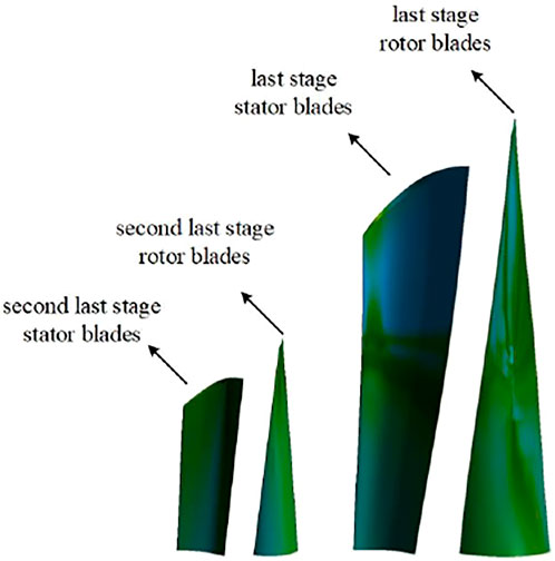
FIGURE 1. The last two-stage single-runner structure.
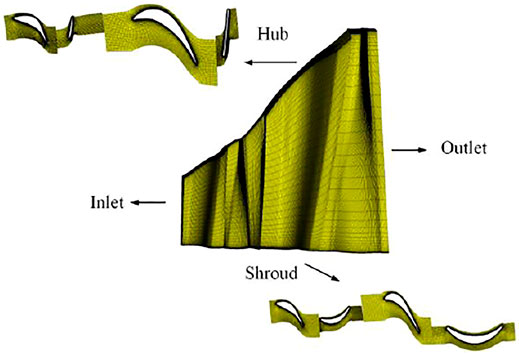
FIGURE 2. Model grid.
The mass flow rate and total temperature are set as the inlet boundary conditions, and the average static pressure is set as the outlet boundary conditions. In this study, the boundary conditions are taken from the rated conditions of steam turbine, the inlet temperature is 357.45 K, the inlet mass flow rate is 1.305 kg/s, the intake humidity is 1.5%, the outlet pressure is 0.0049 MPa, and the rotation speed is 3000 r/min. The commercial software ANSYS-CFX was used to analyze the flow field.
The average outlet humidity of the last stage blade is used to verify the influence of the number of grids on the calculation results, and the result is shown in Figure 3. When the number of grids exceeds 6 million, the number of grids increases and the average outlet humidity of the last stage remains basically unchanged. Considering the calculation accuracy and calculation speed, the total number of grids is 6 million for calculation.
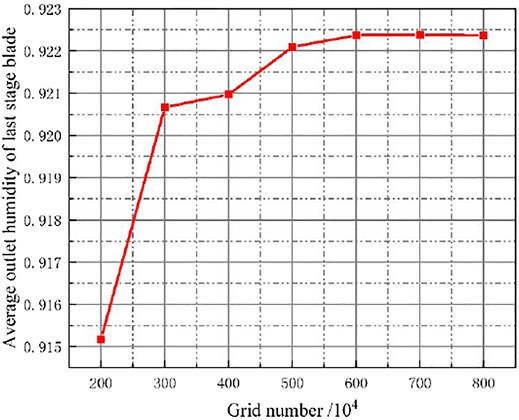
FIGURE 3. Grid independence verification.
In a multiphase flow, each phase has its own velocity field, which is controlled by the conservation of momentum of that phase. In Euler-Euler multiphase flow, the full momentum equation including the phase inertia effect is considered. However, in some cases, if the time scale to reach the equilibrium slip velocity is small, a simplified model can be used to calculate the velocity of the dispersed phase.
The mixed continuity equation is shown in Eq. 1,
where ρm is the mass average mixed fluid density, um is the mass average mixed fluid velocity, and i = 1.
The mixed momentum equation is shown in Eq. 2,
where μm is the mass average mixing viscosity, gj is the gravitational constant, k, n are the phases, a is the volume fraction of the second phase, and j = 2.
The liquid phase volume fraction equation is shown in Eq. 3,
where αl is the volume fraction of liquid phase, ρl is the density of liquid phase, and ul is the velocity of liquid phase.
Slip speed refers to the speed difference between the dispersed liquid phase (l) and the vapor phase (s):
where
In view of the movement law of the secondary water droplets studied in this paper, it is necessary to track the movement state of the secondary water droplets. The Lagrange method is used to track the trajectory of the secondary water droplets in this paper. The Lagrange method adds a random velocity component to the velocity term of the equation of motion. In a rotating coordinate system, the equation of motion of particles derived by Basset, Boussinesq and Oseen is shown in equation (Chen, et al., 2021; Ding, et al., 2021; Wittmann, et al., 2021) Eq. 5.
where mp is the particle quality, u is the velocity, ρ is the density, µ is the fluid kinematic viscosity coefficient, CD is the drag coefficient, Fb is the buoyancy due to gravity, ω is the rotational angular velocity,
The diameter of the primary droplets is small and can flow well with the steam. Therefore, the flow rate of the primary water droplets at the trailing edge of the stator blade is the steam flow rate. Figure 4 shows the distribution of steam velocity in the last two stages of the steam turbine under different loads. It can be seen from the figure that the velocity distribution trend of different loads is the same. Whether it is the trailing edge of the stationary blade or the trailing edge of the moving blade, the velocity of a droplet gradually increases from the tip to the root. And the value of the velocity of a droplet has a small change range, and the size range is between 100 m/s and 500 m/s.
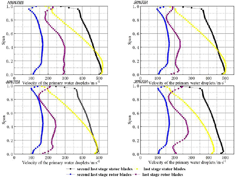
FIGURE 4. Primary water droplet velocity in the last two stages of the steam turbine under different loads.
Figure 5 shows the droplet diameter distribution in the last two stages under different working conditions. After condensing and nucleating, a large number of small water droplets will be produced, and these small water droplets will grow rapidly, forming a primary water droplet with a larger diameter. As can be seen from the above figure, under 100% THA conditions, the diameter of a drop of water is between 0 and 1 μm. Under the other three conditions, the diameter of a drop of water is smaller, between 0 and 0.08 μm. The primary water droplets have the characteristics of small diameter and large number, so most of them can flow well with the steam in the channel without depositing on the surface of the blade. And along the direction of the steam flow, there is a significant growth phenomenon of water droplets, reaching a maximum value at 80% of the blades height of the blade. This is because as the water droplets grow, the number of the primary water droplets at a time increases. The acting frequencies between water droplets increases, and different water droplets collide and converge, forming water droplets with a larger diameter. Under the action of the flow of steam, a small part is deposited on the surface of the blade. For different operating conditions, as the load decreases, the degree of subcooling decreases, the condensation nucleation effect decreases, and the diameter of the water droplets after condensation and nucleation decreases. Therefore, the water droplet size in the last two stages also begins to decrease. Until the 30% THA operating condition The diameter of the water droplet drops to about 0.03 μm.
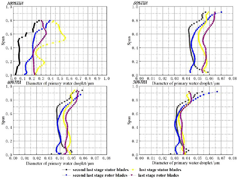
FIGURE 5. The diameter of the primary water droplets in the last two stages of steam turbine under different loads.
Figure 6 shows the deposition and distribution of primary water droplets on the pressure surface and suction surface of the last two stages of steam turbine blades under different loads. From an overall point of view, the most serious part of the deposition occurs in the moving blade, and there is almost no deposition on the suction surface of the stator blade. The deposition severity on the pressure side is higher than that on the suction side, and the deposition at the trailing edge of the stator blade is the most serious. This is because although the primary water droplets formed by condensation and nucleation are small in size and most of them can flow well with the steam, a small part of the water droplets will still be deposited on the stator blades. With the flow of steam and the accumulation of deposits, these small water droplets will slowly move to the stator blades, forming a water film or stream at the trailing edge of the stator blades.
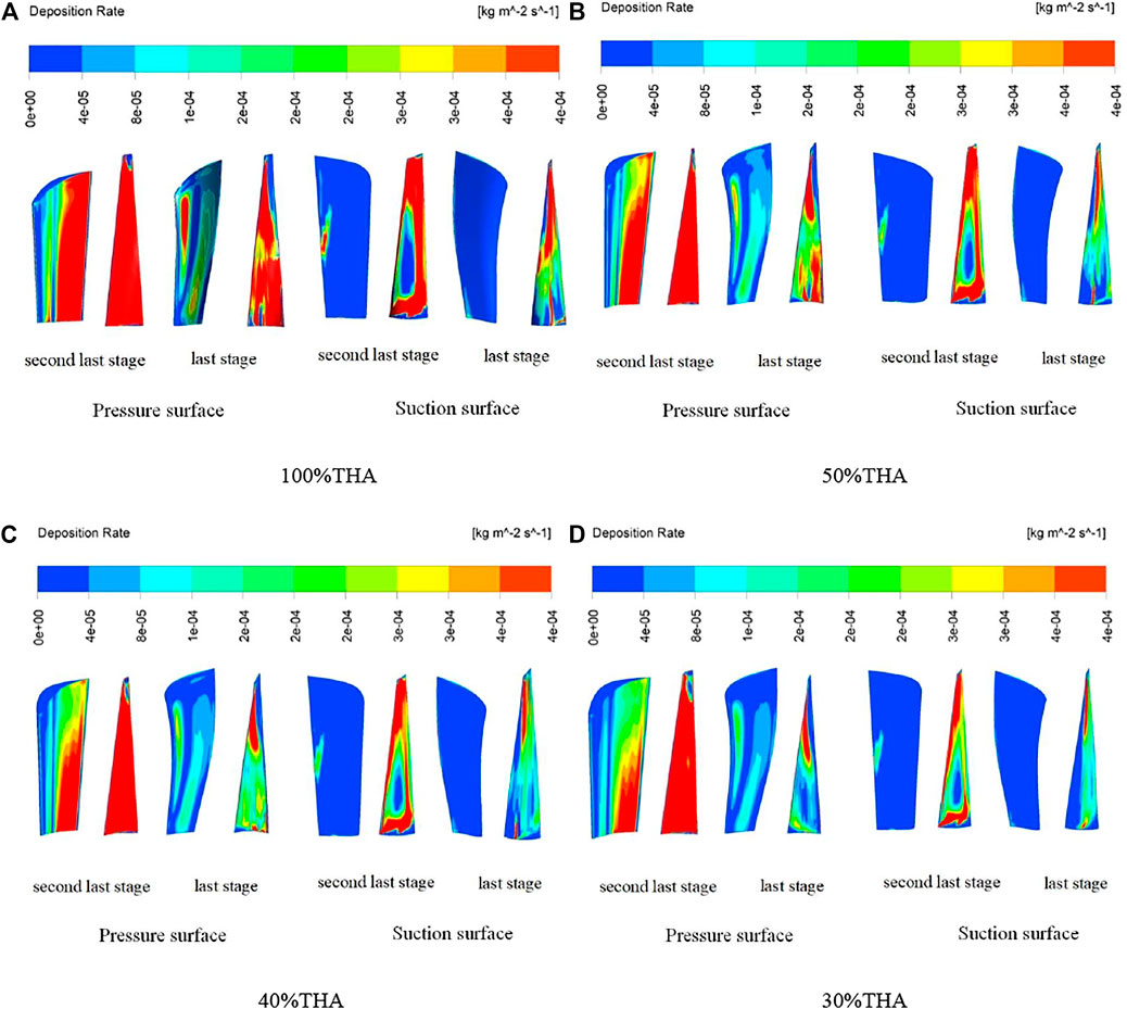
FIGURE 6. The distribution of primary water droplets in the last two stages of steam turbine under different loads. (A) 100%THA. (B) 50%THA. (C) 40%THA. (D) 30%THA.
Comparing these four working conditions, it can be concluded that as the load decreases, the deposition rate of the primary water droplet also decreases. From 100% THA load to 30% THA load the deposition rate of water droplets is decreasing in the last two stage blade whether the pressure face or the suction face. The reduced value is from 0.0001 kg/(m2s) to 0.00004 kg/(m2s). At the same time, there is almost no drop of water on the suction surface of the last stator blades.
Since the secondary water droplets are formed by tearing the water film of the primary water droplets deposited on the trailing edge of the stator blade, the last two stages of the steam turbine are selected as the research objects to simulate the deposition and movement of the secondary water droplets in the wet steam stage. In order to better simulate the results of secondary water droplets depositing on the blade surface, the Lagrangian particle tracking model is used to calculate the water droplet deposition, while considering the actual distribution of the water droplet diameter and mass flow along the blades height (Lain and Sommerfeld, 2020; Han et al., 2021; Lattanzi et al., 2021). The secondary water droplets are only formed by falling off the surface of the trailing edge of the stator blade. When setting the boundary conditions of the secondary water droplets, 20 spray points are evenly set for the second and last stage stator blades along the blades height direction (Yu, 2015), as shown in Figure 7.
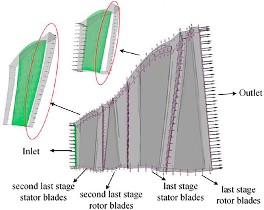
FIGURE 7. Computational domain for calculating the movement of secondary water droplets.
Figure 8 is a diagram of the movement trajectory of the secondary water droplets in the last two stages of the steam turbine. It can be seen from this figure that for its radial direction, the movement location of the secondary water droplets is mainly closer to 30% or more of the blades height. As the load decreases, the more secondary water droplets at the tip of the last stage moving blade. This is because the mass of the secondary water droplets is relatively large. In the process of circular motion, centrifugal force will produce a partial velocity towards the top of the blade, which results in a vacuum zone near the root of the blades, and there are fewer secondary water droplets near the root of the blades.
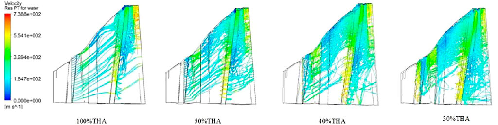
FIGURE 8. The movement trajectory of the secondary water droplets in the last two stages of the steam turbine under different loads.
The wear of a wall due to the erosive effect of particle impacts is a complex function of particle impact, particle and wall properties. For nearly all metals, erosion is found to vary with impact angle and velocity according to the relationship:
where is a dimensionless mass, E is the particle impact velocity and f(γ) is a dimensionless function of the impact angle. The impact angle is the angle in radians between the approaching particle track and the wall. The value of the exponent, n is generally in the range 2.3–2.5 for metals. Finnie’s model of erosive wear (Aungier and Farokhi, 2004) relates the rate of wear to the rate of kinetic energy of impact of particles on the surface, using n = 2:
where
Figure 9 shows the erosion rate density distribution of the secondary water droplet of the last two stage blades of the steam turbine under different load conditions. As can be seen from these figures, the deposition of secondary water droplets in the last stage is more serious than that of the second last stage, which is also one of the reasons for the water erosion of the last stage blades. In the last two stator blades, whether it is the pressure surface or the suction surface of the blade, the deposition of secondary water droplets is light and almost negligible. Hence, the possibility of water erosion at the stator blade is unlikely. This is because the deposited water on the surface of the rotor blade is forced to the inner wall of the cylinder due to the centrifugal force generated by the rotation. Then it is collected and discharged out of the steam turbine through the drainage tank. The stator blade will not have a large number of water droplet collision and erosion phenomena, even if there are some small water droplets flow out of the moving blade with the steam and impact on the stator blades behind. Since the impact speed is very low, it will not cause water erosion of the stator blades.
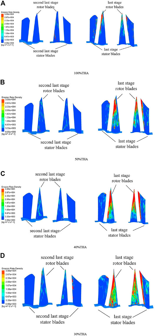
FIGURE 9. The erosion rate density of the secondary water droplets of the last two stage blades of the steam turbine under different loads. (A) 100%THA. (B) 50%THA. (C) 40%THA. (D) 30%THA.
In the last stage blades, the deposition of secondary water droplets is more serious. The most serious part occurs in the last moving blades. This is because the deposited water on the surface of the stator blade and other solids moves to the steam outlet under the action of the steam flow shear stress and tears at the steam outlet to form large-dispersion liquid clusters or droplets. These large water droplets inevitably collide with the rotating blades behind them. The above process is repeated continuously during the operation of the steam turbine, which eventually leads to serious water erosion of the rotor blades. It occurs at 80% of the blades height of the pressure surface and suction surface of the last moving blade, and the maximum value is 3′104 kg/(m2s).
A three-dimensional numerical simulation method was used to comprehensively analyze the movement characteristics of water droplets in the wet steam stage of a 600 MW steam turbine. The main conclusions are as follows:
1) The algebraic slip model and particle tracking model are used to accurately simulate the water droplets movement characteristics in the last two stages of the steam turbine low-pressure cylinder, and the diameter and deposition rate of the primary water droplets under different loads and the erosion rate density of the secondary water droplets are obtained.
2) Under different loads, the diameter of primary water droplets is generally small, ranging from 0 to 1 µm, and its speed is close to the steam velocity. The primary water droplets will be deposited on the surface of the blade in the form of a water film, and the difference of working conditions will not change the location of the deposit of it. Under the four loads, the most serious deposition locations are the trailing edge of the pressure surface of the last two stages and the suction surface of the last moving blades. With the continuous decrease of the loads, the deposition gradually weakened, and no deposition was found on the suction surface of the last two stage.
3) For secondary water droplets with a large diameter, which is between 10 and 300 µm. As the load decreases, the diameter of the secondary water droplets is increasing. Such the large water drop will inevitably corrode the last stage blades in the low pressure cylinder of the steam turbine. Therefore, the lower the load, the larger the diameter of the secondary water droplets, and the most serious erosion. When the load drops to 30% THA, the erosion range of the secondary water droplets expands. The trailing edge of the suction surface of the last stator blades and the pressure surface of the last moving blades above 30% of height are eroded.
The raw data supporting the conclusions of this article will be made available by the authors, without undue reservation.
SF: modeling and simulation, writing papers; YW and KY: simulation boundary condition setting, text modification; WG: verification of the authenticity of numerical simulation results; YF and JW: calculation condition selection, overall reviewing.
This work was supported by the National Key R and D Program of China (Grant No. 2017YFB0902100) and the China Postdoctoral Science Foundation (Grant No. 2021T140154).
WG was employed by the company Zhejiang Zheneng Technology Research Institute Co., Ltd.
The remaining authors declare that the research was conducted in the absence of any commercial or financial relationships that could be construed as a potential conflict of interest.
All claims expressed in this article are solely those of the authors and do not necessarily represent those of their affiliated organizations, or those of the publisher, the editors and the reviewers. Any product that may be evaluated in this article, or claim that may be made by its manufacturer, is not guaranteed or endorsed by the publisher.
Ahmad, M. (2018). An Overview of Droplet Impact Erosion, Related Theory and Protection Measures in Steam Turbines. Cavitation: Selected Issues 91, 91–108. doi:10.5772/intechopen.80768
Ahmad, M., Schatz, M., and Casey, M. V. (2018). An Empirical Approach to Predict Droplet Impact Erosion in Low-Pressure Stages of Steam Turbines. Wear 402-403, 57–63. doi:10.1515/TJJ.2009.26.3.20110.1016/j.wear.2018.02.004
Aungier, R., and Farokhi, S. (2004). Axial-flow Compressors: a Strategy for Aerodynamic Design and Analysis. Appl. Mech. Rev. 57 (4), B22. doi:10.1115/1.1786589
Bohn, D., Uno, T., Yoshida, T., Betcher, C., Frohnheiser, J., and Weidtmann, K. (2021). Numerical and Experimental Study of Droplet-Film-Interaction for Low Pressure Steam Turbine Erosion protection Applications. J. Glob. Power Propuls. Soc. 5, 90–103. doi:10.33737/jgpps/140173
Chen, X., Zhou, X., Xia, X., Xie, X., Lu, P., and Feng, Y. (2021). Modeling of the Transport, Hygroscopic Growth, and Deposition of Multi-Component Droplets in a Simplified Airway with Realistic thermal Boundary Conditions. J. aerosol Sci. 151, 105626. doi:10.1016/j.jaerosci.2020.105626
Ding, H., Tian, Y., Wen, C., Wang, C., and Sun, C. (2021). Polydispersed Droplet Spectrum and Exergy Analysis in Wet Steam Flows Using Method of Moments. Appl. Therm. Eng. 182, 116148. doi:10.1016/j.applthermaleng.2020.116148
Gribin, V. G., Tishchenko, A. A., Tishchenko, V. A., Gavrilov, I. Y., Sorokin, I. Y., and Alexeev, R. A. (2017). Experimental Study of the Features of the Motion of Liquid-phase Particles in the Interblade Channel of the Nozzle Array of a Steam Turbine1. Power Technol. Eng. 51 (1), 82–88. doi:10.1007/s10749-017-0788-x
Han, L., Zhang, G. F., Wang, Y., and Wei, X. Z. (2021). Investigation of Erosion Influence in Distribution System and Nozzle Structure of Pelton Turbine. Renew. Energ. 178, 1119–1128. doi:10.1016/j.renene.2021.06.056
Han, X., Zeng, W., and Han, Z. (2020). Investigating the Dehumidification Characteristics of the Low-Pressure Stage with Blade Surface Heating. Appl. Therm. Eng. 164, 114538. doi:10.1016/j.applthermaleng.2019.114538
He, C., Jiayu, B., Xingang, W., Chaoshan, X., Zhiyong, Y., and Shoutao, T. (2021). “Current Situation and Achievements of Flexible Transformation of Thermal Power Units in China,” in 2021 3rd Asia Energy and Electrical Engineering Symposium (AEEES), Chengdu, China, March 2021, 852–856. doi:10.1109/AEEES51875.2021.9403189
Lain, S., and Sommerfeld, M. (2020). Influence of Droplet Collision Modelling in Euler/Lagrange Calculations of spray Evolution. Int. J. Multiphase Flow 132, 103392. doi:10.1016/j.ijmultiphaseflow.2020.103392
Lattanzi, A. M., Tavanashad, V., Subramaniam, S., and Capecelatro, J. (2021). A Stochastic Model for the Hydrodynamic Force in Euler--Lagrange Simulations of Particle-Laden Flows. Available at: https://www.researchgate.net/publication/350253457_A_stochastic_model_for_the_hydrodynamic_force_in_Euler--Lagrange_simulations_of_particle-laden_flows (Accessed March 19, 2021).
Li, N., Zhao, Q. X., Zhou, Q., Chen, X., Xu, T., Hui, S., et al. (2009). Flow Field of Water Drops in a Blade Channel: Numerical Simulation of Water Drop Erosion on Turbine Blades. Int. J. Turbo Jet Engines 26 (3), 201–221. doi:10.1515/TJJ.2009.26.3.201
Li, X., Li, W., Zhang, R., Jiang, T., Chen, H., and Li, G. (2020). Collaborative Scheduling and Flexibility Assessment of Integrated Electricity and District Heating Systems Utilizing thermal Inertia of District Heating Network and Aggregated Buildings. Appl. Energ. 258, 114021–11402120. doi:10.1016/j.apenergy.2019.114021
Mirhoseini, M. S., and Boroomand, M. (2017). Control of Wetness Fraction and Liquid Droplet Size in Wet Steam Two Phase Flows with Hot Steam Injection. Meccanica 53, 193–207. doi:10.1007/s11012-017-0729-7
Petr, V., and Kolovratnik, M. (2000). Modelling of the Droplet Size Distribution in a Low-Pressure Steam Turbine. Proc. Inst. Mech. Eng. A: J. Power Energ. 214 (2), 145–152. doi:10.1243/0957650001538245
Rossi, P., Raheem, A., and Abhari, R. S. (2018). Numerical Model of Liquid Film Formation and Breakup in Last Stage of a Low-Pressure Steam Turbine. J. Eng. Gas Turbines Power 140 (3), 032602. doi:10.1115/1.4037912
Schuster, S., Benra, F.-K., and Brillert, D. (2017). Droplet Deposition in Radial Turbines. Eur. J. Mech. - B/Fluids 61, 289–296. doi:10.1016/j.euromechflu.2016.09.002
Sengupta, B., and Bhattacharya, C. (2017). Influence of Blade Shape and Water Droplet Size on Fractional Deposition in the Last Stages of Steam Turbine. Int. J. Emerging Technol. Adv. Eng. 7, 164–172. doi:10.1007/s10749-017-0788-x
Sengupta, B., and Bhattacharya, C. (2018). Investigation of Energy Loss on Fractional Deposition in Last Stages of Condensing Steam Turbine Due to Blade Shape and Moisture Droplet Size. J. Eng. Gas Turbines Power Trans. Asme 140, 072601. doi:10.1115/1.4038544
Sengupta, B. (2016). “Droplet Deposition in the Last Stage of Steam Turbine,”. Thesis for: MSc- Energy Technology (Gyeongnam, South Korea: Gyeongsang National University). doi:10.13140/RG.2.2.24372.24967
Simon, A., Marcelet, M., Hérard, J.-M., Dorey, J.-M., and Lance, M. (2016). “A Model for Liquid Films in Steam Turbines and Preliminary Validations,” in Proceedings of the ASME Turbo Expo 2016: Turbomachinery Technical Conference and Exposition. Volume 8: Microturbines, Turbochargers and Small Turbomachines; Steam Turbines, Seoul, South Korea, June 2016. doi:10.1115/GT2016-56148
Starzmann, J., Kaluza, P., Casey, M. V., and Sieverding, F. (2014). On Kinematic Relaxation and Deposition of Water Droplets in the Last Stages of Low Pressure Steam Turbines. J. Turbomach. 136 (7), 071001. doi:10.1115/1.4025584
Synáč, J., Rudas, B., and Luxa, M. (2021). Erosion of Steam Turbine Last Stages. AIP Conf. Proc. 2323, 060008. AIP Publishing LLC. doi:10.1063/5.0042949
Tatsuno, K., and Nagao, S. (1986). Water Droplet Size Measurements in an Experimental Steam Turbine Using an Optical Fiber Droplet Sizer. J. Heat Transfer 108 (4), 939–945. doi:10.1115/1.3247038
Tishchenko, V. A., Alekseev, R. A., and Gavrilov, I. Y. (2018). A Model of the Motion of Erosion-Hazardous Droplets in Steam Turbines' Interblade Channels. Therm. Eng. 65 (12), 885–892. doi:10.1134/S0040601518120108
Tishchenko, V. A., and Alekseev, R. A. (2019). Numerically Simulating the Formation and Motion of Water Films and Erosion-Hazardous Droplets in Flow-Through Parts of Steam Turbines. Therm. Eng. 66 (11), 830–838. doi:10.1134/S0040601519110053
Tishchenko, V., and Alekseev, R. (2018). Numerical Modeling of the Mechanism of Coarse Droplets Deposition on Surfaces of a Steam Turbine Nozzle Blade cascade. J. Phys. Conf. Ser. 1128, 012137. IOP Publishing. doi:10.1088/1742-6596/1128/1/012137
Wang, J., Zhang, S., Huo, J., Zhou, Y., Li, L., and Han, T. (2021). Dispatch Optimization of thermal Power Unit Flexibility Transformation under the Deep Peak Shaving Demand Based on Invasive weed Optimization. J. Clean. Prod. 315, 128047. doi:10.1016/j.jclepro.2021.128047
White, A. J., and Hounslow, M. J. (2000). Modelling Droplet Size Distributions in Polydispersed Wet-Steam Flows. Int. J. Heat Mass Transfer 43 (11), 1873–1884. doi:10.1016/S0017-9310(99)00273-2
Wittmann, T., Bode, C., and Friedrichs, J. (2021). The Feasibility of an Euler-Lagrange Approach for the Modeling of Wet Steam. J. Eng. Gas Turbines Power 143 (4), 041004. doi:10.1115/1.4049859
Yan, C.-w., Wang, B., and Chen, J. (2019). “Numerical Research of Movement Characteristic and Deposition Ratio on Cylinder Wall of Secondary Water Droplet between Penultimate Stage and Last Stage,”IOP Conf. Ser. Earth Environ. Sci. 330, 032063. doi:10.1088/1755-1315/330/3/032063
Yao, H., and Zhou, X. (2018). A Pioneering Method for Reducing Water Droplet Erosion. J. Fluids Eng. 140 (6). doi:10.1115/1.4038802
Yu, X. (2015). “Numerical Study on the Flow Characteristics of Wet Steam in the Low Pressure Stage of a Steam Turbine,”. Doctoral dissertation (Wuhan: Wuhan University).
Keywords: steam turbine, low-pressure cylinder, last two stages, lower loads, water droplet movement characteristics
Citation: Fan S, Wang Y, Yao K, Fan Y, Wan J and Gu W (2021) Research on Water Droplet Movement Characteristics in the Last Two Stages of Low-Pressure Cylinder of Steam Turbine Under Low Load Conditions. Front. Energy Res. 9:798305. doi: 10.3389/fenrg.2021.798305
Received: 20 October 2021; Accepted: 24 November 2021;
Published: 22 December 2021.
Edited by:
Wei Wang, North China Electric Power University, ChinaReviewed by:
Xiao Wu, Southeast University, ChinaCopyright © 2021 Fan, Wang, Yao, Fan, Wan and Gu. This is an open-access article distributed under the terms of the Creative Commons Attribution License (CC BY). The use, distribution or reproduction in other forums is permitted, provided the original author(s) and the copyright owner(s) are credited and that the original publication in this journal is cited, in accordance with accepted academic practice. No use, distribution or reproduction is permitted which does not comply with these terms.
*Correspondence: Kun Yao, MTliMzUzMDA5QHN0dS5oaXQuZWR1LmNu; Jie Wan, d2FuamllQGhpdC5lZHUuY24=
Disclaimer: All claims expressed in this article are solely those of the authors and do not necessarily represent those of their affiliated organizations, or those of the publisher, the editors and the reviewers. Any product that may be evaluated in this article or claim that may be made by its manufacturer is not guaranteed or endorsed by the publisher.
Research integrity at Frontiers
Learn more about the work of our research integrity team to safeguard the quality of each article we publish.